
Steps
13
- 0.1 WorkBench 2.0 - 3D Printers 13 steps

User-Contributed Guide
This guide is not managed by the site's staff.
Quiz
0
Introduction
To start the build, make sure you have a clean and empty working area dedicated to this assembly. This way, if you need to take a break, you don't have to move everything part way through the build. This decreases the risk of losing, or mismatching, components from the kit. Always have your tools close and organized in order to optimize your workflow. The steps in the Build guide indicate what components are required and how many to use. In the step title there is a number, for example, (x2) means you have to repeat the step 2 times.
It is strongly recommended to assemble the kit on a known flat surface (such as a solid table, work surface or similar). Assembling the kit on a carpeted floor, or other non-flat surface, can cause the finished frame to not be square.
- The table top is not supplied, the user is meant to source it locally. A 20mm thick MDF board is recommended.
Table top dimensions (sourced by user):
- For V-Core3.1 200/300 - Table: 550x600mm
- For V-Core3.1 200/300/400/500 - Table: 750x800mm
Please note: This guide is based upon building a 550x600 WorkBench 2.0 for 3D printers. Measurements for the 750x800 WorkBench 2.0 are provided in the relevant steps.
CAD Model:
Workbench 2.0 - 550x600: Fusion360 CAD Model
Workbench 2.0 - 750x800: Fusion360 CAD Model
-
-
It is recommended to have the following tools available for assembling the WorkBench 2.0 for 3D printers:
-
Allen Key 8mm
-
Tape measure or calipers
-
Engineers Square
-
-
-
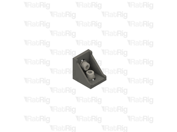
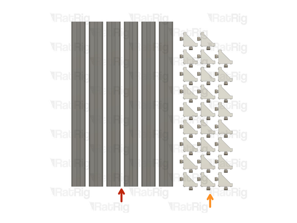
24x 90 Degree Cast Corner
-
48x M8x16 Cap Head Screw
-
48x 4040 Drop-in T-Nut - M8
-
48x M8 Washer
-
-
-
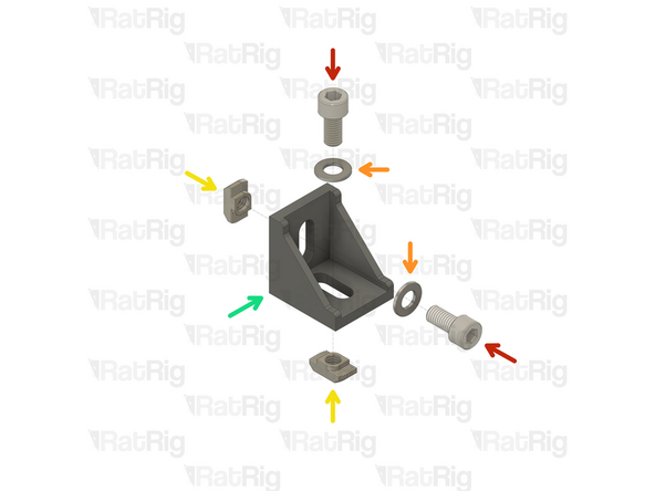
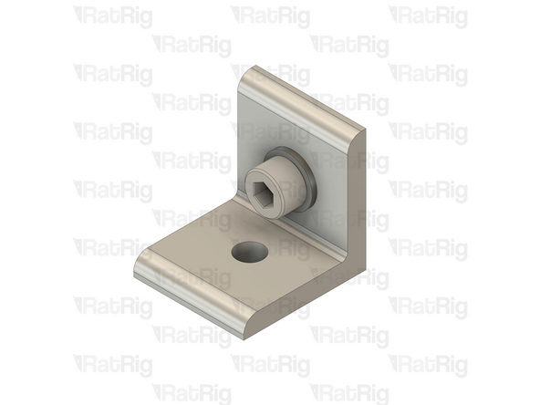
M8x16 Cap Head Screw
-
M8 Washer
-
4040 Drop-in T-Nut - M8
-
4040 Cast 90 Degree Corner
-
Loosely thread the 4040 T-Nuts on to the M8x16 screws. Do not tighten them at this point.
-
-
-
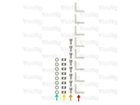
8x Simple 90 Degree Corner
-
8x M8x16 Cap Head Screw
-
8x 4040 Drop-in T-Nut - M8
-
8x M8 Washer
-
-
-
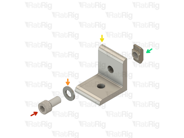
M8x16 Cap Head Screw
-
M8 Washer
-
Simple 90 Degree Corner
-
4040 Drop-in T-Nut - M8
-
Loosely thread the 4040 T-Nuts on to the M8x16 screws. Do not tighten them at this point.
-
-
-
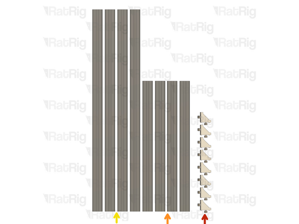
8x 4040 Cast Corners assemblies
-
4x 520mm 4040 Extrusion
-
720mm for the 750x800 WorkBench 2.0
-
4x 805mm 4040 Extrusion
-
615mm for the 750x800 WorkBench 2.0
-
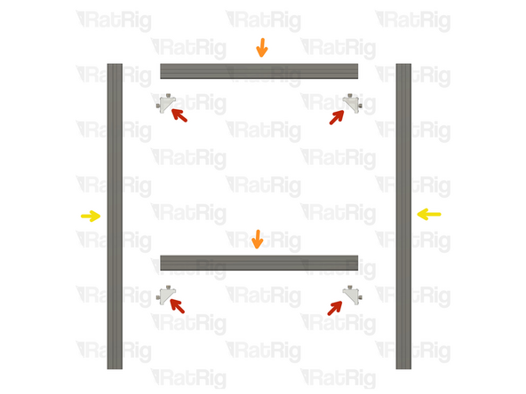
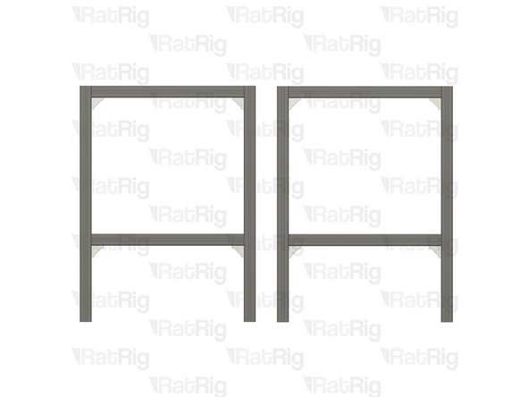
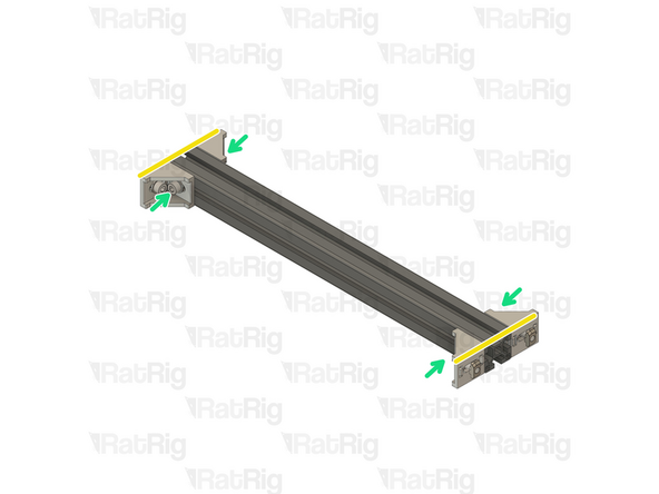
Assemble two side frames as shown.
-
Ensure the extrusions are flush and square with the 4040 cast corner assemblies before and after tightening the screws.
-
-
-
6x 470mm 4040 Extrusion
-
670mm for the 750x800 WorkBench 2.0
-
16x 4040 Cast Corners assemblies
-
-
-
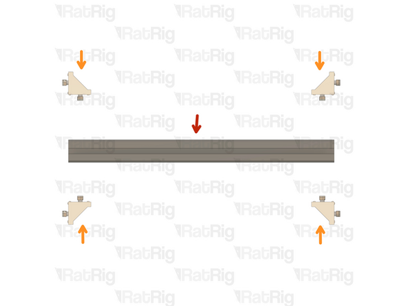
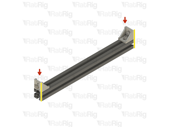
470mm 4040 Extrusion
-
670mm for the 750x800 WorkBench 2.0
-
4x 4040 cast corner
-
Check all of the cast corners to make sure they are flush with the extrusion ends
-
Secure the cast corners to the extrusion by fastening the four M8x16 screws
-
Repeat this step to create the second assembly.
-
-
-
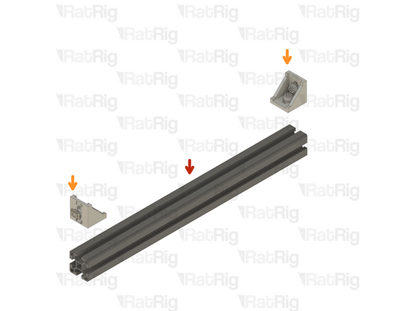
470mm 4040 Extrusion
-
670mm for the 750x800 WorkBench 2.0
-
4x 4040 cast corner
-
Check all of the cast corners to make sure they are flush with the extrusion ends
-
Secure the cast corners to the extrusion by fastening the four M8x16 screws
-
Repeat this step to create a total of four assemblies.
-
-
-
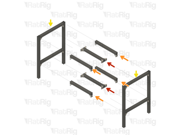
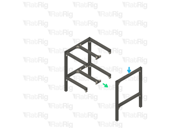
2x Middle frame extrusion from Step 8
-
4x Side frame extrusion from Step 9
-
2x Side frame from Step 6
-
Attach the remaining extrusion assemblies to one of the side frames, as pictured, by fitting the t-nuts inside the slots and tightening the screws.
-
Attach the second side frame to the assembly.
-
Ensure the extrusions are flush and square with the 4040 cast corner assemblies before and after tightening the screws.
-
-
-
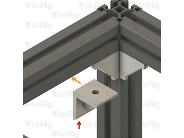
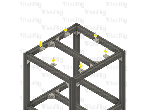
6x 4040 simple 90 degree corner assembly
-
Mount the corner assembly on the frame top extrusion as shown
-
Repeat the steps above for the remaining five corner assemblies
-
Position each corner roughly in the middle of the available space, as shown.
-
-
-
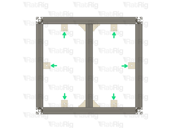
Due to their small footprint, these workbenches should be secured to the wall for added safety and stability. These brackets are included for this purpose
-
Place the wall mounts on the back of the WorkBench 2.0
-
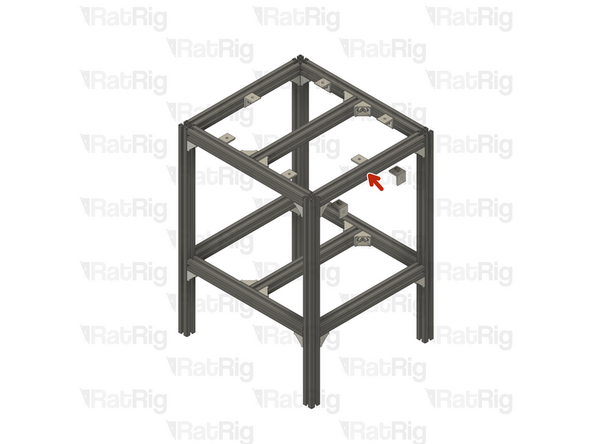
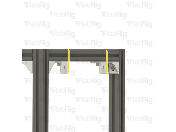
2x 4040 simple 90 degree corner assembly
-
Mount the corner assembly on the bottom of the extrusion, making sure the bracket is oriented outwards.
-
-
-
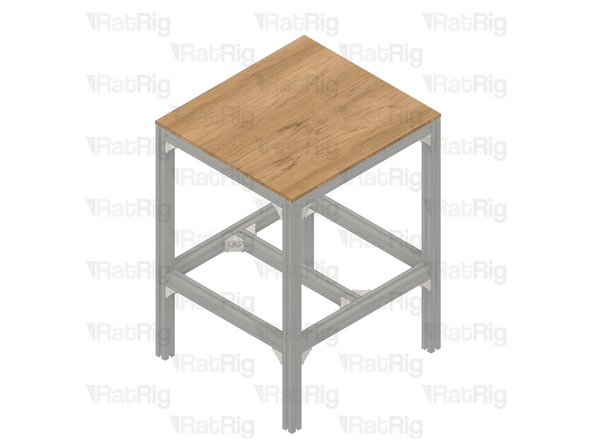
The table top is not included in the kit, you will have to source it locally. It is recommended to use a table top with a thickness no less than 20mm. The required dimensions are as follows:
-
For V-Core 200/300 - Workbench: 550x600mm
-
For V-Core 200/300/400/500 - Workbench: 750x800mm
-


Cancel: I did not complete this guide.
2 other people completed this guide.

2 Comments
I've had quite some issues following the guide for my 900x850mm workbench since the measurements aren't specified for this size. An update would be helpful for future builders.
Davide Depau - Open Reply
I had no issues following the guide for my 750x800 workbench. I printed some endcaps for the legs since none were included. You can find the model here: https://www.printables.com/model/1160907...