Introduction
NOTE: all measurements in this guide assume you’re assembling the 300x300x300mm machine!
As a general rule, add 100mm to the measurements if you’re assembling a 400 machine, or 200mm if you’re assembling a 500 machine (this may not be valid for some of the measurements provided).
Video Overview
-
-
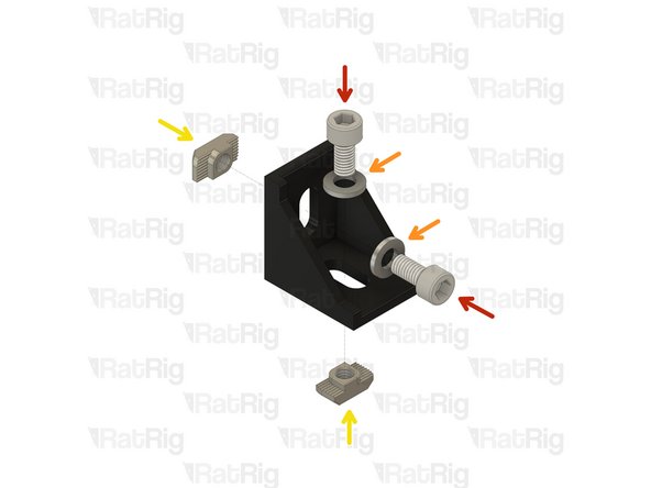
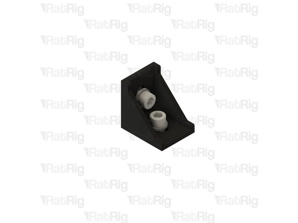
Repeat this step for 4 Joining plates (2 are mirrored)
-
Cap Head Screw M6x12
-
Cap Head Screw M5x18
-
Rubber foot
-
Joining plate
-
3030 Drop-in T-Nut M6
-
3030 Drop-in T-Nut M5
-
Set the T-Nuts in position, but do not tighten them just yet.
-
-
-
Set up all remaining Joining Plates in the kit
-
Cap Head Screw M6x12mm
-
3030 Drop-in T-Nut M6
-
Set T-Nuts into position, but do not tighten them just yet.
-
-
-
Set up all Corner Brackets (x12) in your kit.
-
Cap Head Screw M6x12
-
M6 Washer
-
3030 Drop-in T-Nut M6
-
Set T-Nuts into position, but do not tighten them just yet.
-
-
-
For the next step you will need:
-
420mm 3030 extrusion
-
440mm 3030 extrusion
-
450mm 3030 extrusion
-
-
-
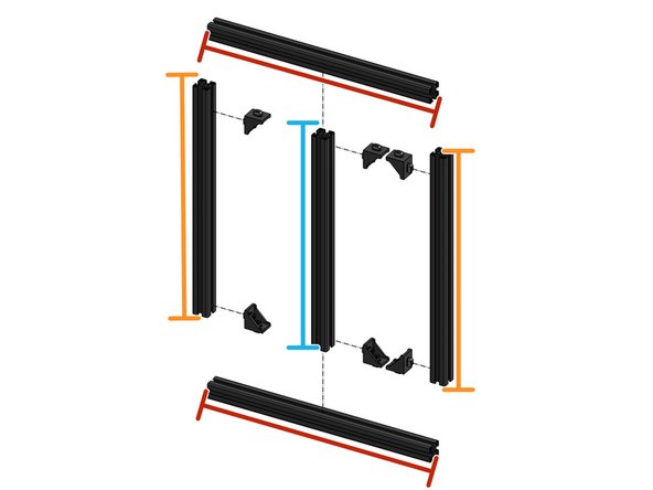
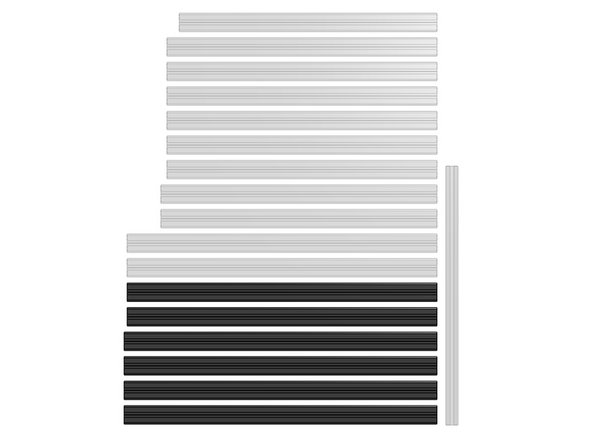
Prepare the 3030 extrusions:
-
440mm
-
450mm
-
420mm
-
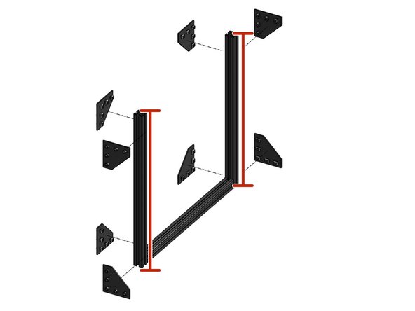
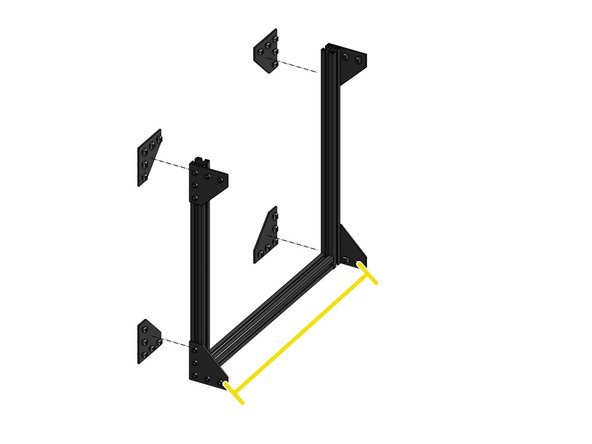
Attach 6 Corner Brackets to the ends of the vertical extrusions
-
205mm
-
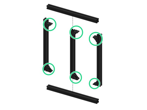
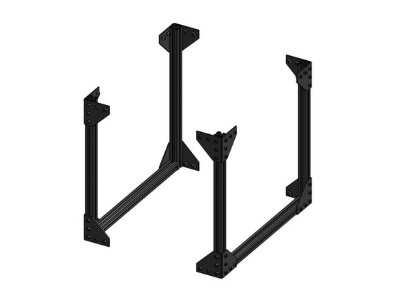
Carefully attach the extrusions by tightening all screws on the Corner Brackets. Make sure the frame is perfectly square. A flat surface may help.
-
-
-
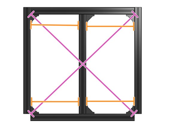
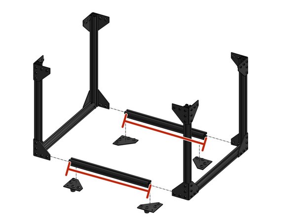
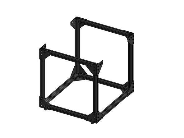
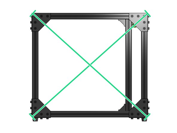
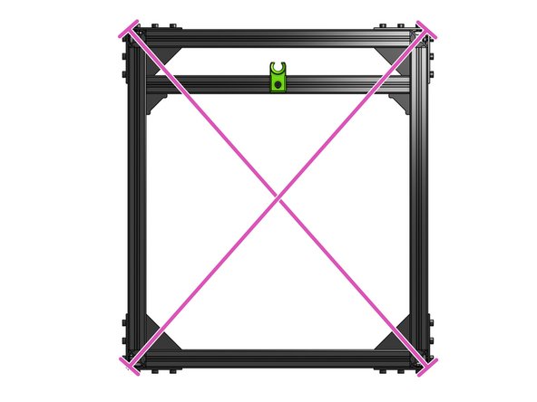
Make sure the frame is square. The diagonal lengths should be equal
-
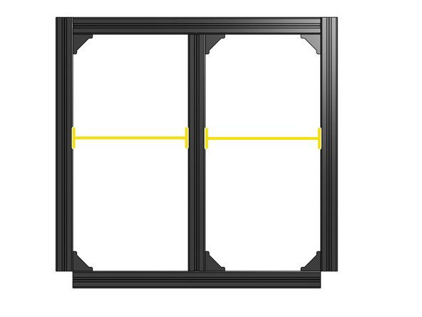
The middle extrusion should be in the exact middle of the inner frame - 205mm from the side extrusions
-
-
-
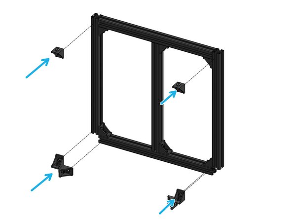
Loosely attach 6 corner brackets. Don't worry about alignment, you will adjust their position in a moment.
-
-
-
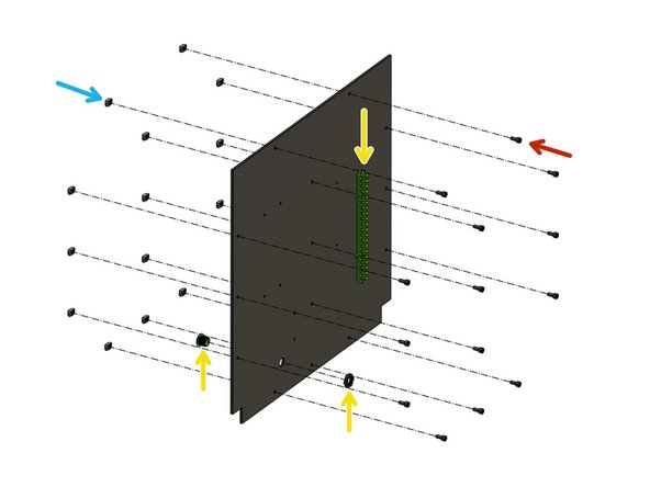
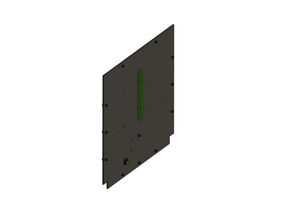
If you are opting for a back panel this is a good time to attach it. It's going to be difficult later.
-
Panels are not supplied by Rat Rig, they are meant to be sourced locally. DXF files are provided for each panel and machine size.
-
CAUTION: Panel should not be thicker than 4mm, or it will not fit.
-
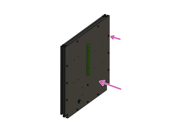
If needed, drill the M6 holes and fasten the Cap Head Screw M6x12 through them
-
Attach the 3030 Drop-in T-Nut M6 to the screws
-
Some kits may use M5x12 screws with M5 T-Nuts for this step. If this is the case for your kit, it will include 18 M5x12 Cap head screws. If not, it will include only 4 of those screws.
-
Cable Management Printed Parts (Optional and not included in the kit shipped by Rat Rig)
-
Fit the panel on the inner frame and fasten all of the screws
-
-
-
CAUTION: These lengths are very similar, do not mix them up!
-
Prepare 3030 extrusions:
-
2x 505mm
-
4x 510mm
-
-
-
Attach the corner plate assemblies to the Z extrusions (510mm)
-
Add the Y extrusion (505mm)
-
Repeat for the other side of the frame
-
Don't worry about the top Y extrusions - those will be added later
-
-
-
Prepare the X 3030 extrusions:
-
4x 440mm
-
-
-
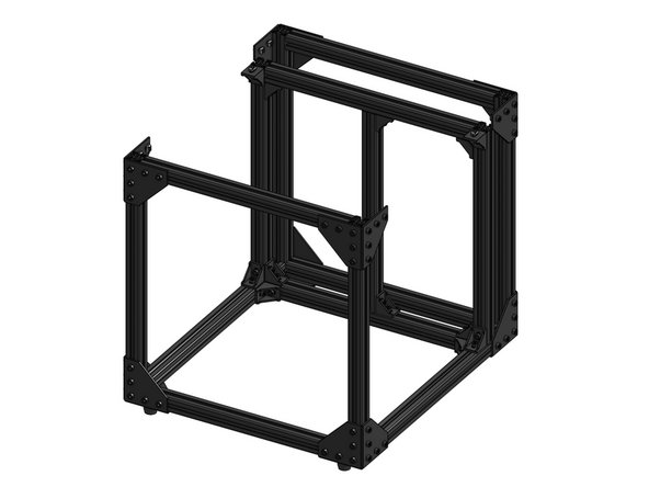
Join the two frame sides with 440mm X extrusions
-
Attach the bottom corner assemblies
-
Add the top 440mm X extrusions
-
-
-
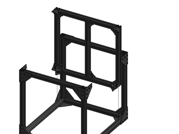
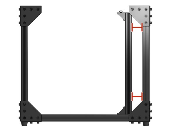
Insert the inner frame into the main frame
-
You will need to loosen the bottom corner assemblies a little
-
The distance between the inner frame and the main Z extrusions should be 47mm
-
-
-
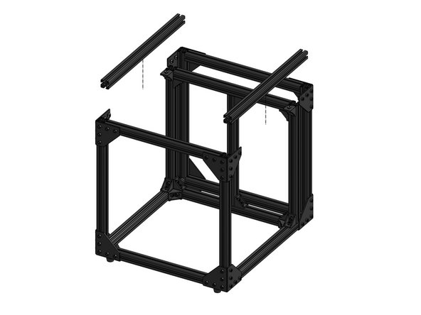
Prepare the Y 3030 extrusions
-
2x 505mm
-
-
-
Attach the top Y extrusions
-
You will need to loosen the corner brackets in the top of the inner frame
-
Again, ensure the inner frame is parallel to the main frame - the distance between those should be 47mm
-
-
-
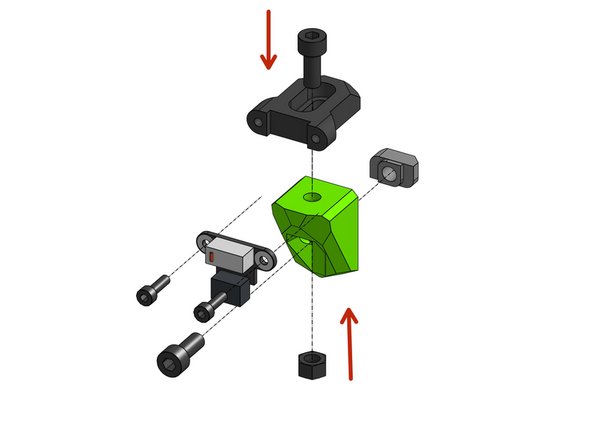
Backpull the M5 hex locking nut and fasten the two printed parts together with a Cap Head Screw M5x12
-
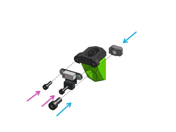
Attach the 3030 M5 T-nut to a Cap Head Screw M5x12 through the bottom part
-
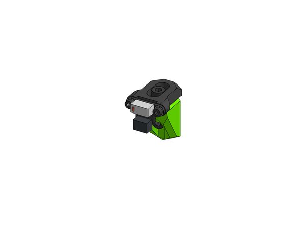
Fasten the endstop to the top printed part with 2x Cap Head Screws M3x10
-
-
-
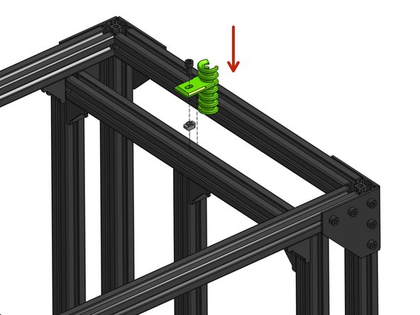
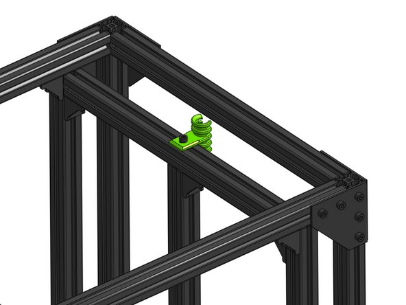
Thread the M6x12mm screw through the back cable guide and attach the 3030 M6 T-nut
-
Screw the part the the center of the inner frame's top extrusion
-
Don’t tighten too hard
-
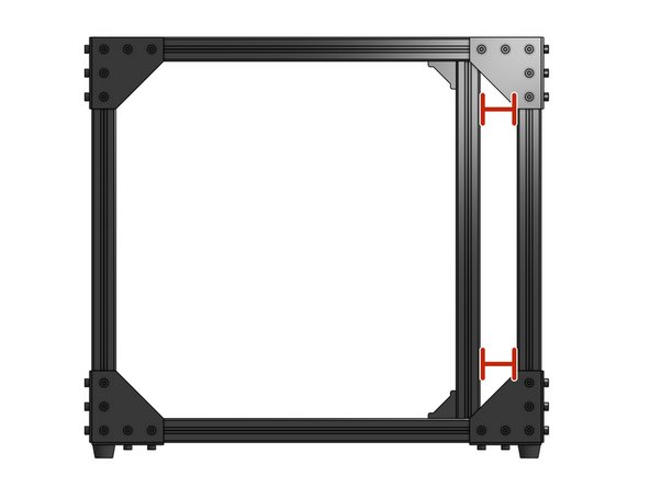
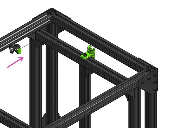
Attach the Y endstop to the frame
-
-
-
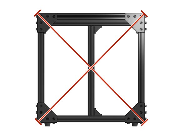
VERY IMPORTANT: a frame that is not square will produce noise and will wear out parts like bearings and belts
-
Go around your frame and check the diagonal lengths - those need to be as equal as possible (a difference of less than 1mm is acceptable)
-
Front and back
-
Right and left
-
Top and bottom
-