Steps
71
- 12. Enclosure 2.0 Assembly 71 steps

In Progress
This guide is currently being written. Reload periodically to see the latest changes.

User-Contributed Guide
This guide is not managed by the site's staff.

Private
This guide will not appear in search results and can only be viewed by team members!
Quiz
0
Introduction
Please note: All measurements provided in this guide are based upon building a 300x300 V-Core 3.
If you are building a machine of a different size, the following adjustments can be made to the stated extrusion lengths:
- 200x200: Remove 100mm
- 400x400: Add 100mm
- 500x500: Add 200mm
-
-
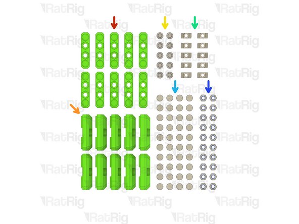
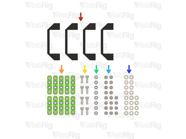
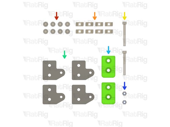
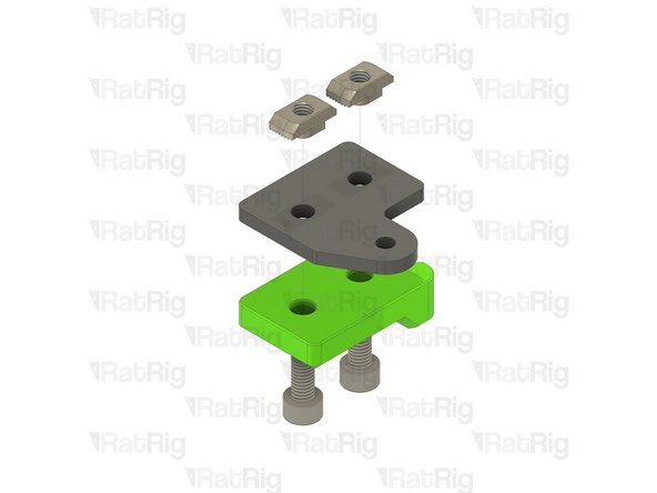
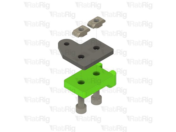
6x T-Shape Joining Plate for 3030
-
30x M6x12 Cap Head Screw
-
30x 3030 Drop-in T-Nut - M6
-
-
-
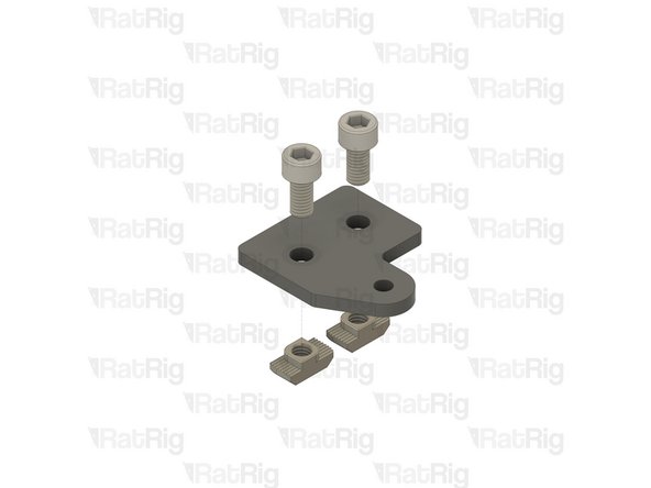
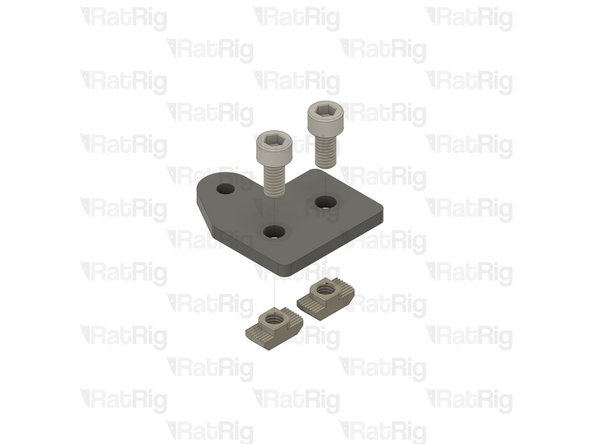
M6x12 Cap Head Screw
-
3030 Drop In T-Nut - M6
-
T-Shape Joining Plate for 3030
-
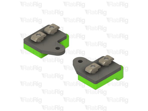
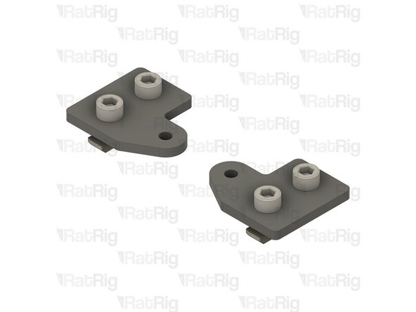
Loosely thread the 3030 T-Nuts onto the M6x12 screws. Do not tighten them at this point.
-
Set these plates aside until Step !!
-
-
-
10x panel_magnet_holder printed part
-
10x panel_magnet_mount printed part
-
10x M6x12 Cap Head Screw
-
10x 3030 Drop-in T-Nut - M6
-
40x Neodymium Disc Magnet - 10x4mm
-
20x M6 Nylon Locking Hex Nut
-
-
-
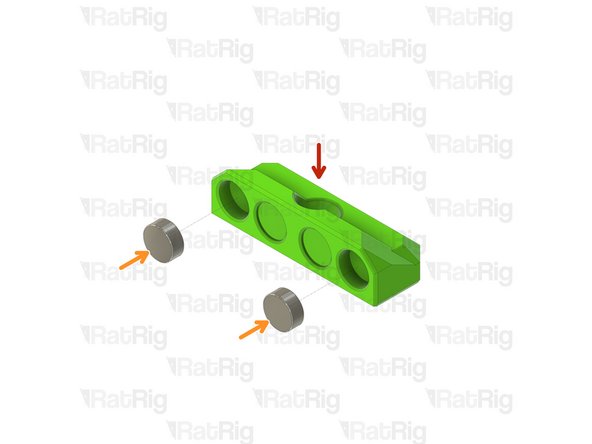
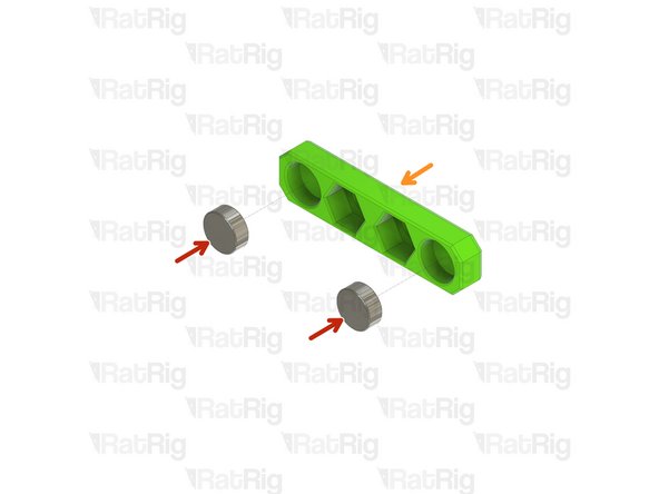
panel_magnet_mount printed part
-
Neodymium Disc Magnet - 10x4mm
-
The magnets are designed to be a tight fit into the printed part. If they are loose, or you wish to secure them further, place a few drops of cyanoacrylate glue into the printed part before adding the magnet
-
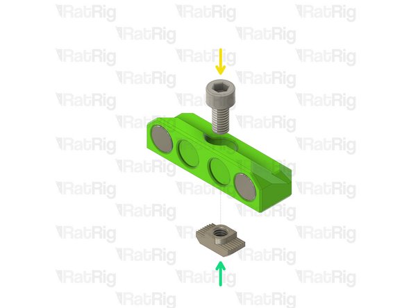
M6x12 Cap Head Screw
-
3030 Drop-in T-Nut - M6
-
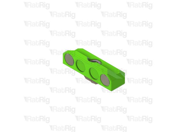
Loosely thread the 3030 T-Nuts onto the M6x12 screws. Do not tighten them at this point.
-
Set these assemblies aside until Step !!
-
-
-
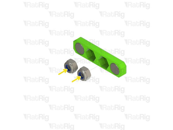
panel_magnet_holder printed part
-
Neodymium Disc Magnet - 10x4mm
-
The magnets are designed to be a tight fit into the printed part. If they are loose, or you wish to secure them further, place a few drops of cyanoacrylate glue into the printed part before adding the magnet
-
M6 Nylon Locking Hex Nut
-
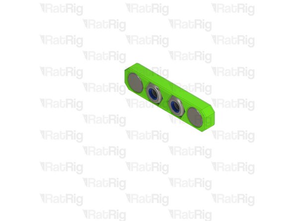
Set these assemblies aside until Steps 7, 8 & 11
-
-
-
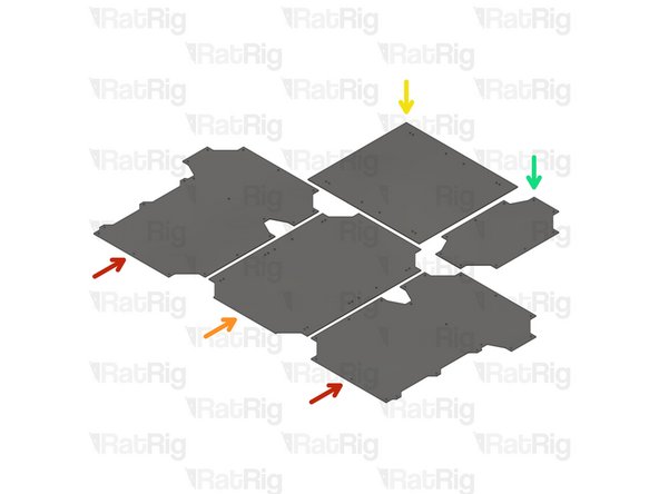
RatRig provides DXF and STEP files for you to have your own panels produced locally. These are available for download on the RatRig V-Core 3 GitHub repository
-
2x panel_enc2_side_size
-
1x panel_enc2_door_size
-
1x panel_enc2_top_size
-
1x panel_enc2_back_size
-
Use the file with the correct size for your printer (200, 300, 400 or 500)
-
-
-
4x Rat Rig nylon door handle
-
10x Panel magnet mount assemblies from Step 5
-
8x M6x16 Cap Head Screw
-
8x M6 Nylon Locking Hex Nut
-
24x M6x12 Cap Head Screw
-
24x M6 Washer
-
-
-
There are 6 magnet mount positions on the door (or 4 on the 200). Repeat the following for each of them
-
panel_enc2_door_size
-
M6x12 Cap Head Screw
-
M6 Washer
-
Panel magnet mount assembly from Step 5
-
Take care not to over tighten the M6x12 screw as you can damage the printed parts
-
-
-
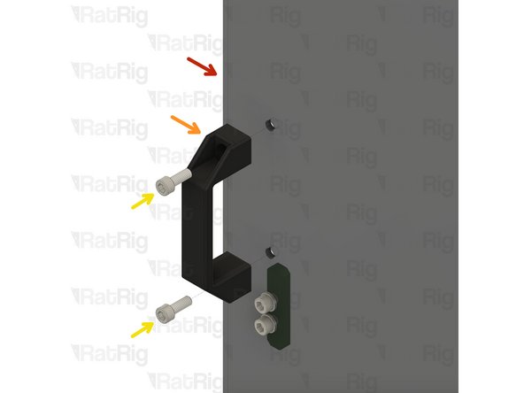
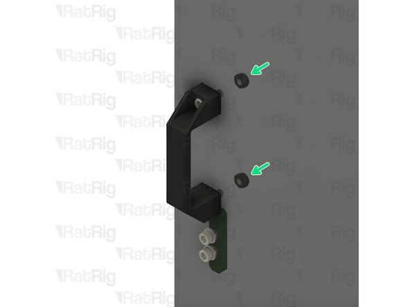
There are 2 magnet mount positions on the door. Repeat the following for each of them
-
panel_enc2_door_size
-
Rat Rig nylon door handle
-
M6x16 Cap Head Screw
-
M6 Nylon Locking Hex Nut
-
Do not overly tighten the M6 nylon locking hex nuts when securing the handles, as this can cause the panel to warp which will prevent a good seal to the printer
-
-
-
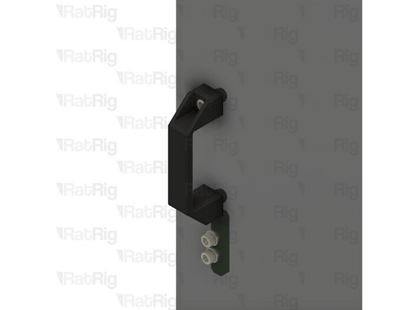
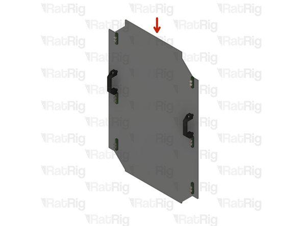
Completed door panel assembly
-
Set the completed door assembly aside until Step !!
-
-
-
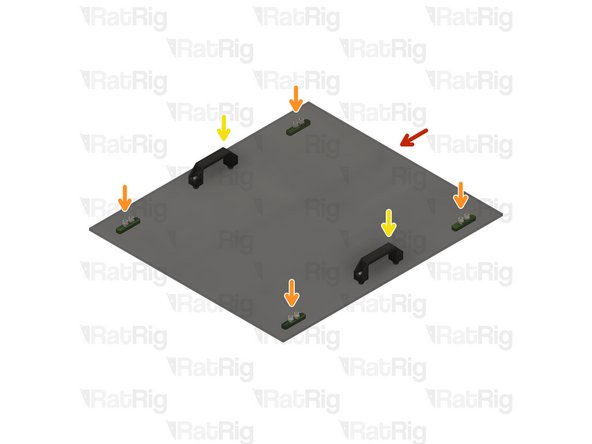
panel_enc2_top_size
-
Install four of the panel magnet mount assemblies to the top panel
-
Take care not to over tighten the M6x12 screw as you can damage the printed parts
-
Install two of the Rat Rig nylon handles to the top panel
-
Do not overly tighten the M6 nylon locking hex nuts when securing the handles, as this can cause the panel to warp which will prevent a good seal to the printer
-
Set the completed top assembly aside until Step !!
-
-
-
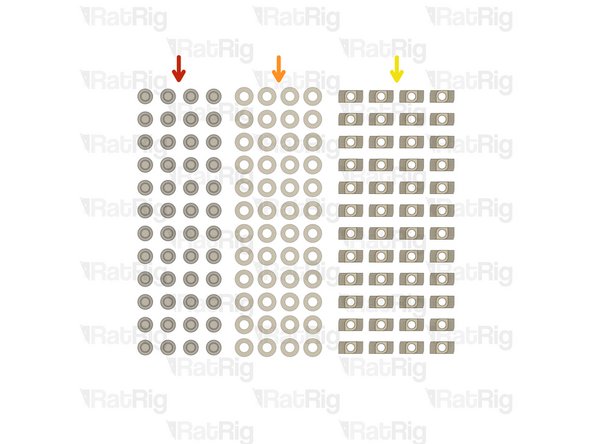
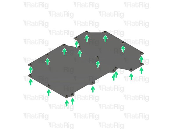
48x M6x12 Cap Head Screw
-
48x M6 Washer
-
48x 3030 Drop-in T-Nut - M6
-
-
-
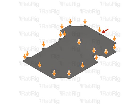
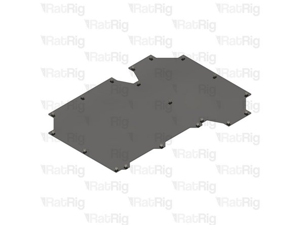
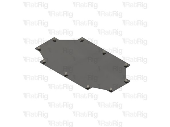
panel_enc2_side_size
-
M6 Washer
-
M6x12 Cap Head Screw
-
3030 Drop-in T-Nut - M6
-
Loosely thread the 3030 T-Nuts onto the M6x12 screws. Do not tighten them at this point.
-
-
-
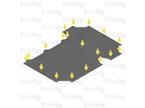
Repeat the previous steps to install an M6x12 cap head screw, M6 washer and 3030 drop-in t-nut to each hole on the remaining panels as shown
-
Set all panels aside until Step !!
-
-
-
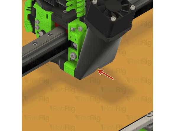
EVA3 toolhead assembly
-
Upper CoreXY belt tensioner
-
Lower CoreXY belt tensioner
-
Loosen both CoreXY belt tensioners as shown
-
-
-
Left CoreXY motor assembly
-
M3x35 Cap Head Screw
-
Support the NEMA17 stepper motor whilst removing the M3x35 screws
-
Remove the four M3x35 screws to release the NEMA17 motor
-
Left CoreXY NEMA17 stepper motor
-
Set the 4x M3x35 screws and NEMA17 stepper motor aside until Steps 20 & 21
-
-
-
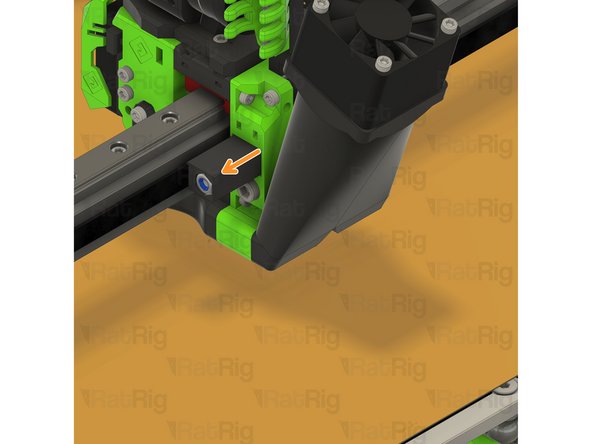
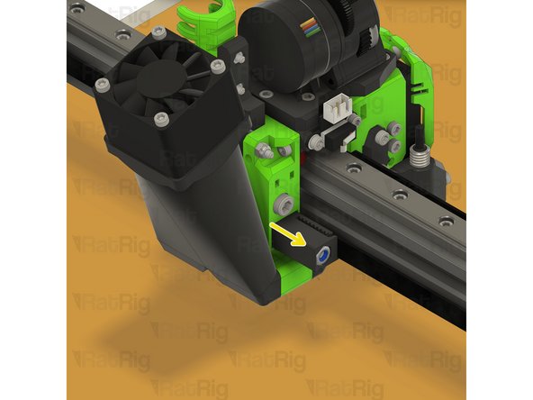
M5x40 Cap Head Screw
-
Loosen, but do not remove, both of the M5x40 screws
-
-
-
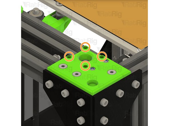
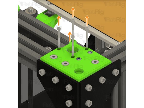
M6x14 Countersink Screw
-
Loosen the three M6x14 screws
-
Lift the upper CoreXY motor cage assembly from the machine
-
Remove all 3 M6x14 screws, and 3030 t-nuts, from the printed part
-
Remove the two M5 nylon locking nuts from the printed part
-
-
-
xy_motor_cage_top_left_3.1_cutout printed part
-
M6x14 Countersink Screw
-
M5 Nylon Locking Hex Nut
-
3030 Drop-in T-Nut - M6
-
Assemble the new CoreXY motor cage top as shown
-
Install the xy_motor_cage_top_left_3.1_cutout assembly onto the frame as shown
-
Make sure the belt loop remains in the position shown
-
Tighten the three marked M6x14 screws to secure the CoreXY motor cage top to the frame
-
-
-
M5x40 Cap Head Screw
-
Tighten the M5x40 screws to secure the bearing stacks into the CoreXY motor cage top
-
CoreXY NEMA17 stepper motor from Step 16
-
Position the NEMA17 motor up and into the motor cage from below,
-
-
-
Insert the M3x35 screws from Step 16 into the CoreXY motor cage as shown, and fasten them to secure the NEMA17 motor to the mount
-
-
-
Repeat Steps 16 thru 21 to replace the right side CoreXY motor cage top
-
-
-
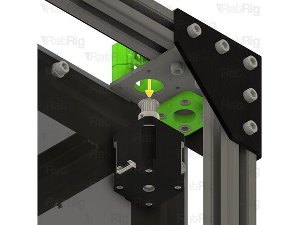
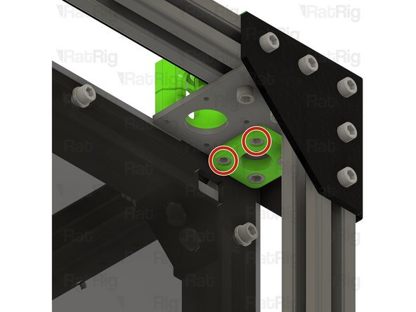
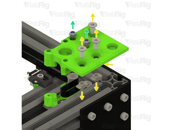
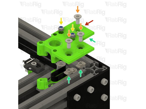
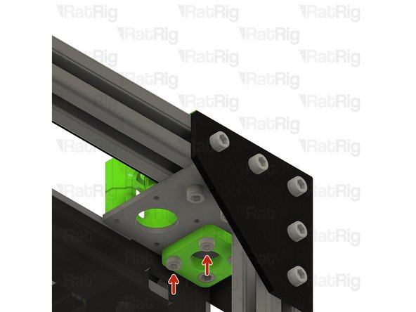
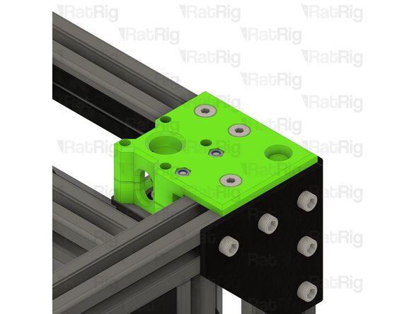
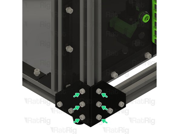
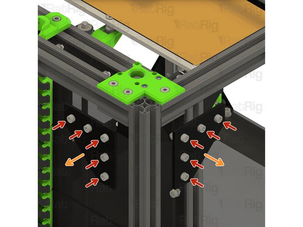
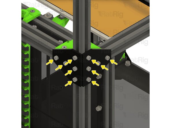
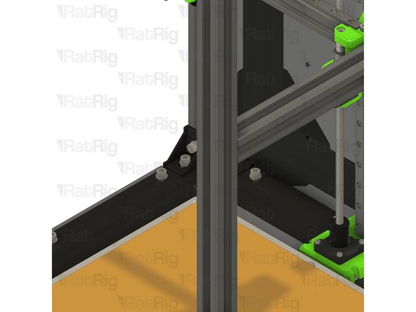
M6x12 Cap Head Screw
-
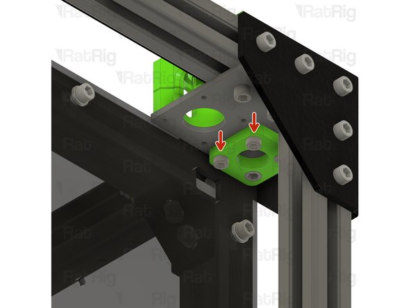
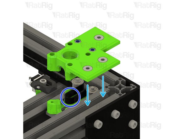
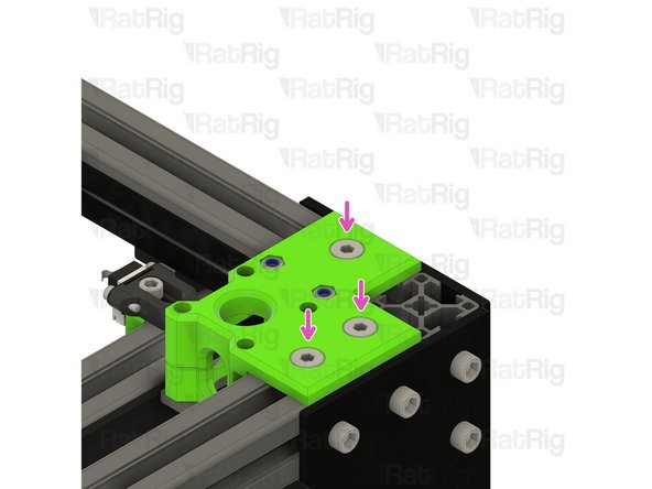
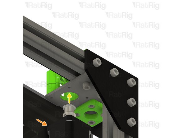
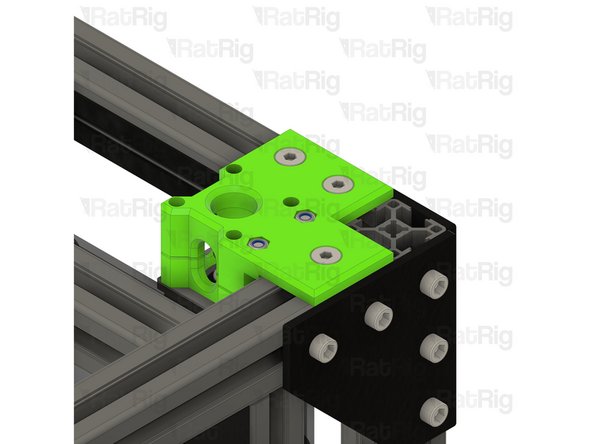
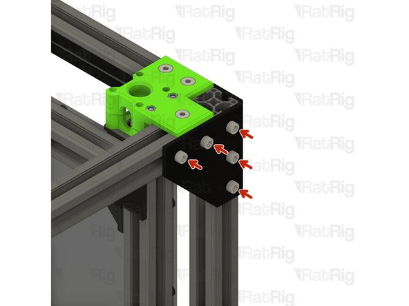
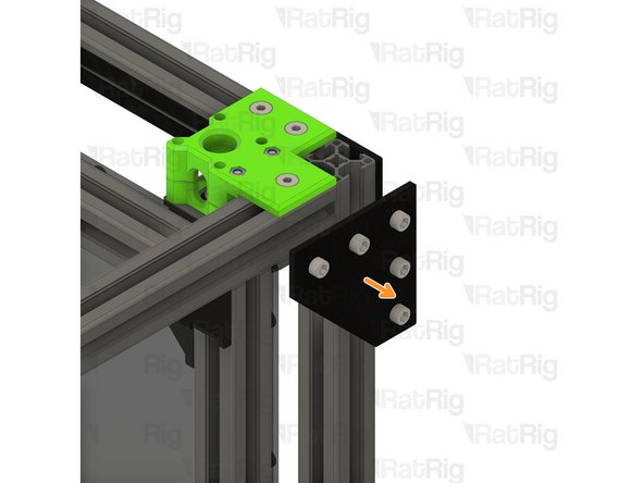
Loosen all of the M6x12 screws and remove the corner plate assembly
-
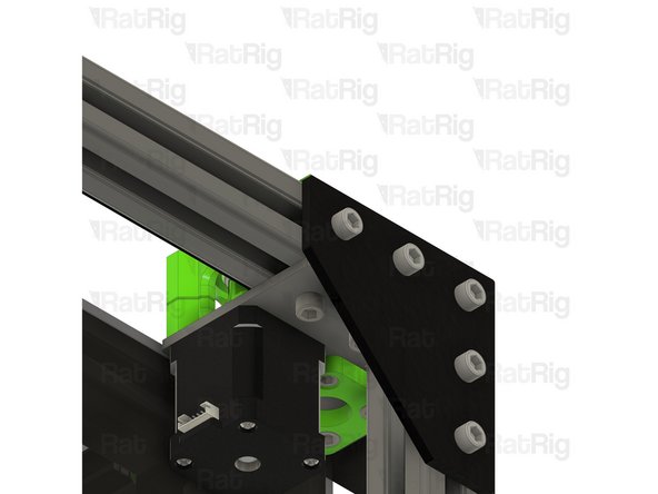
Loosen all of the M6x12 screws and remove the second corner plate assembly as well
-
Set these corner plate assemblies aside until Step !!
-
-
-
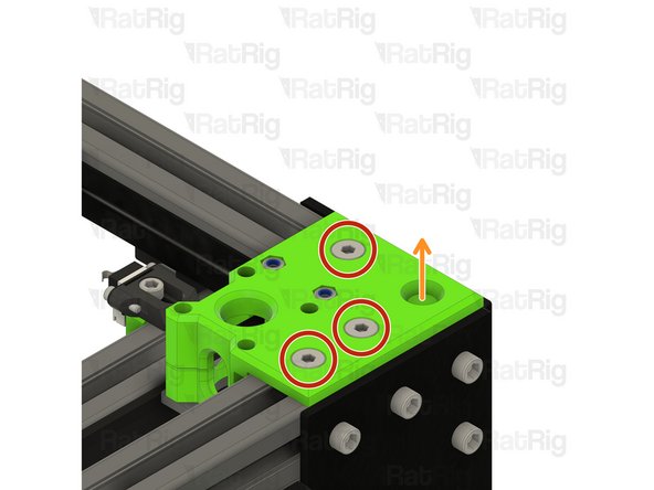
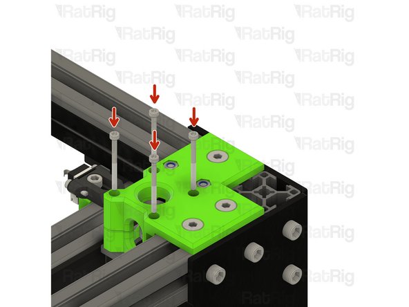
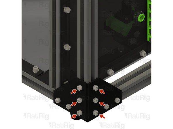
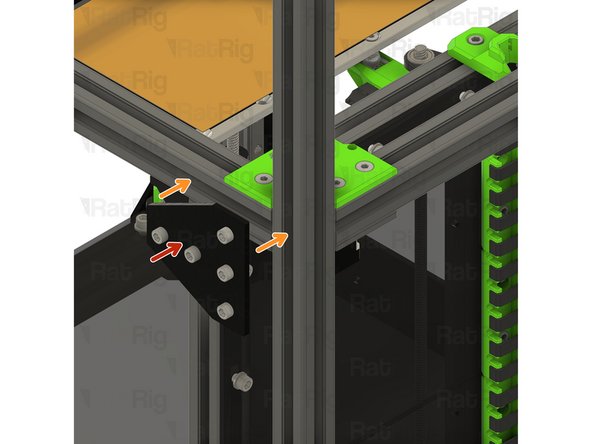
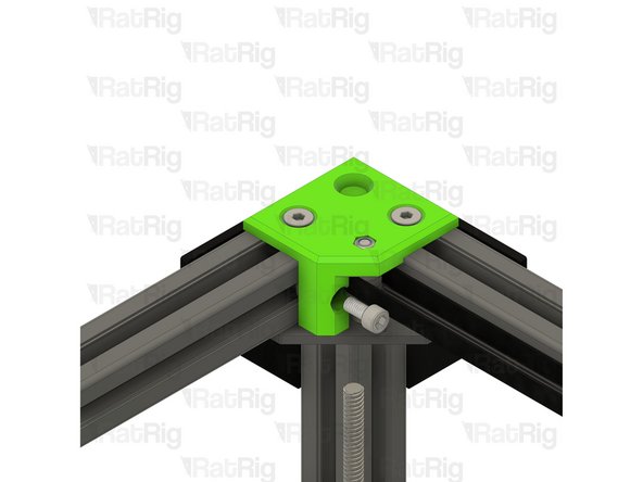
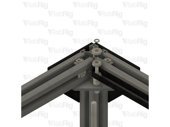
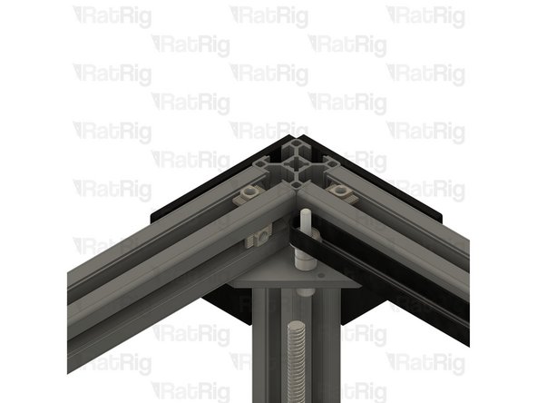
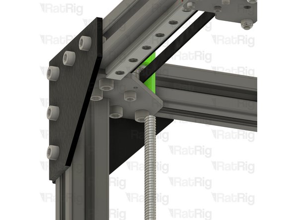
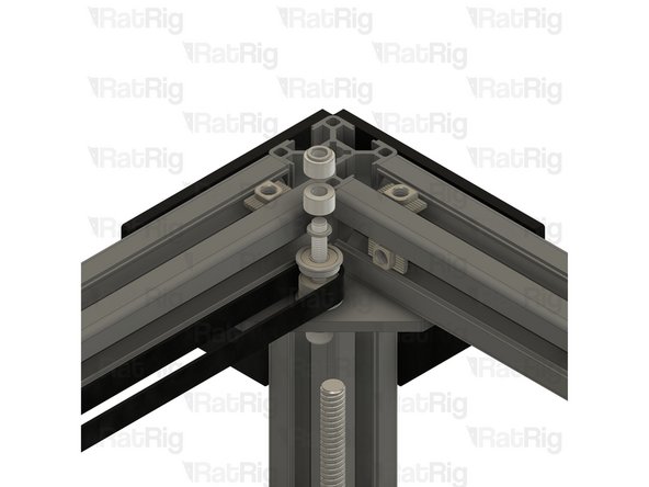
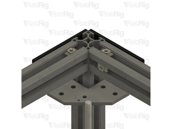
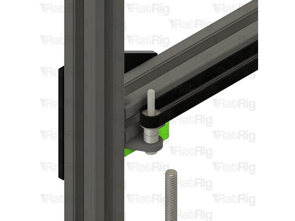
M6x12 Cap Head Screw
-
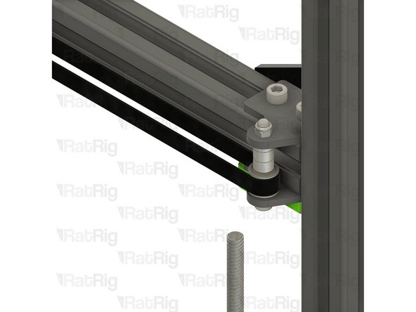
Loosen but do not remove the marked M6x12 screws
-
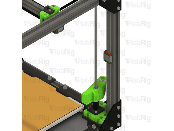
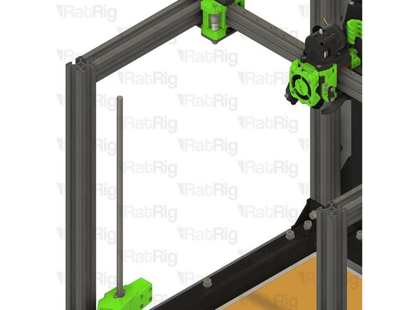
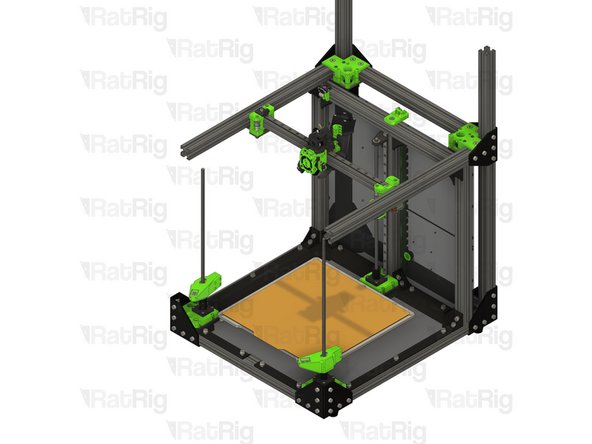
Rear right 3030 extrusion
-
Pull the 3030 extrusion upwards to remove it from the machine frame
-
-
-
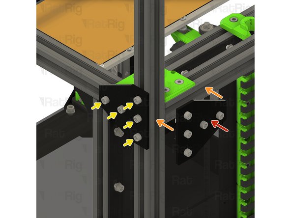
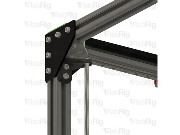
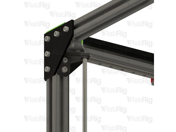
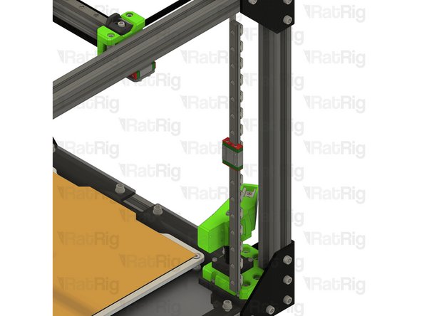
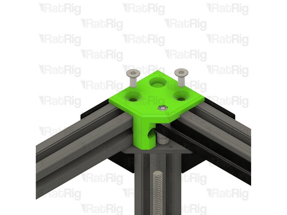
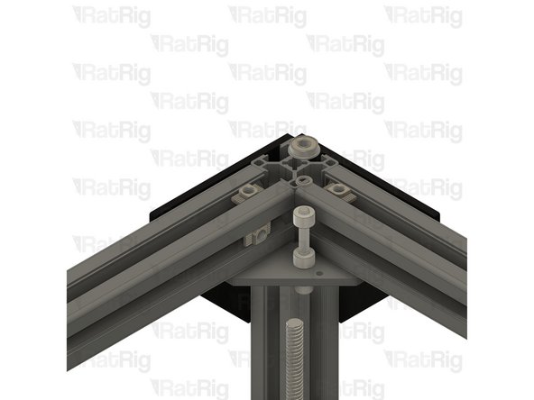
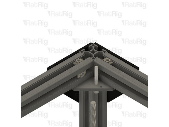
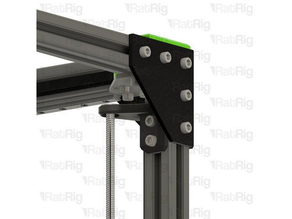
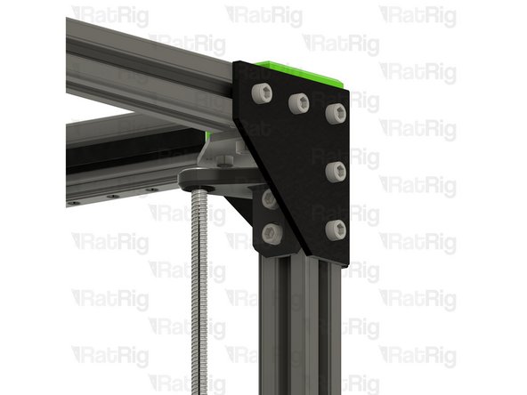
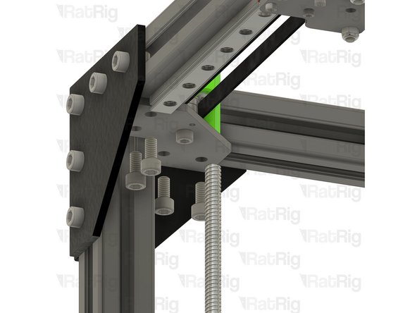
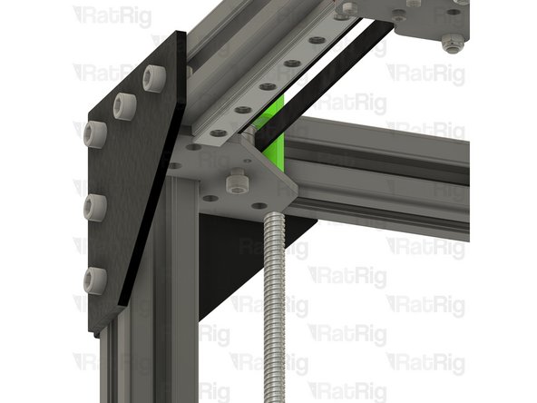
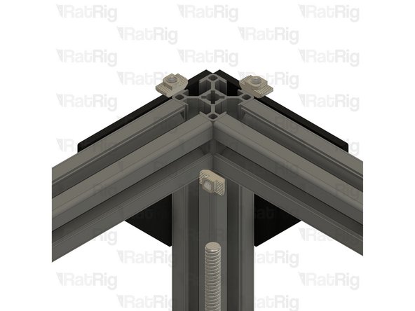
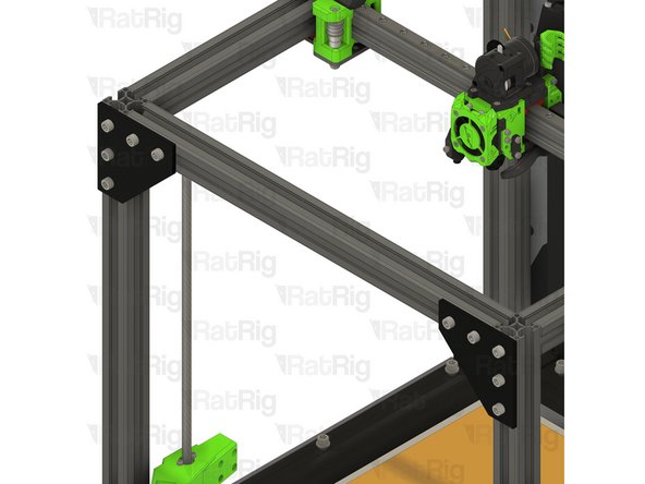
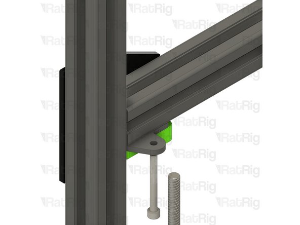
760mm 3030 Extrusion
-
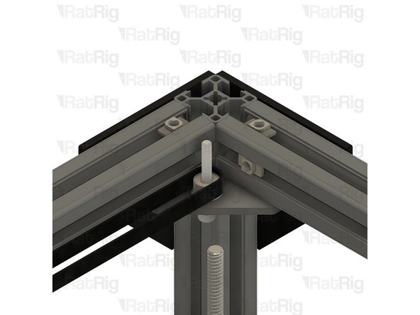
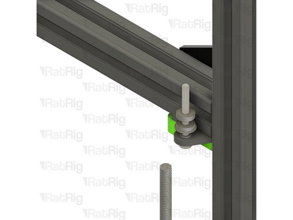
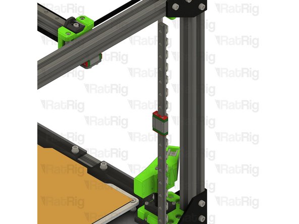
Insert the 3030 extrusion into the bottom corner plate assemblies
-
You may need to rotate the 3030 t-nuts to insert the 3030 extrusion
-
Measure from the underside of the rear extrusion, to the top of the newly installed extrusion. It should measure either 230mm (for a V-Core 3 200) or 280mm (for a V-Core 300, 400 or 500)
-
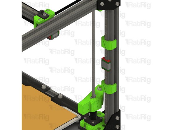
Ensure the extrusion is fully inserted before continuting
-
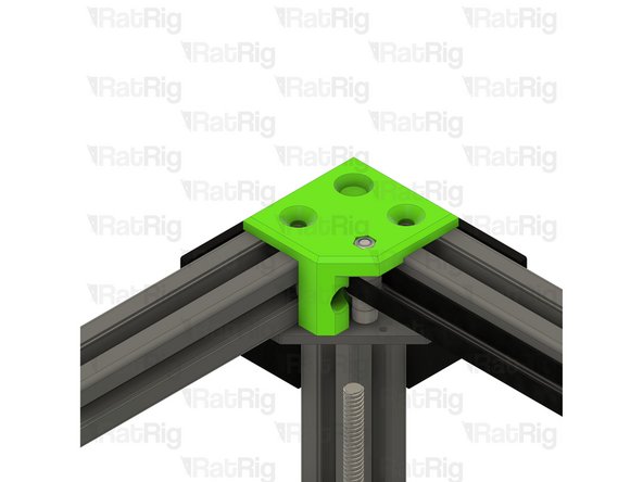
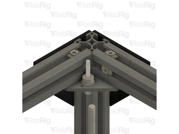
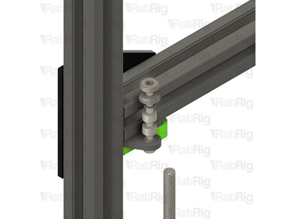
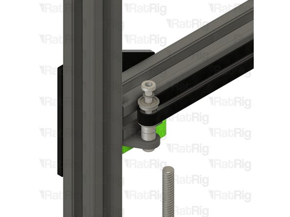
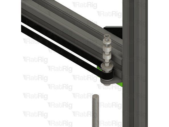
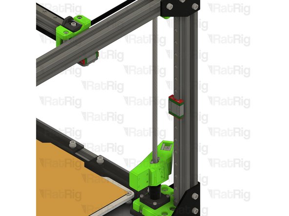
Tighten the six marked M6x12 screws to secure the 3030 extrusion to the frame
-
-
-
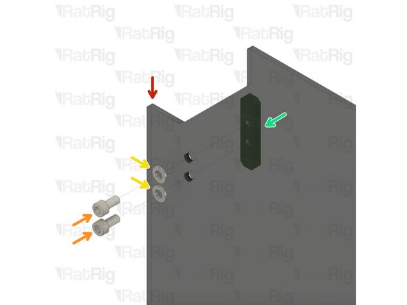
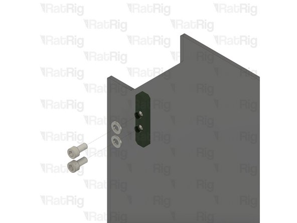
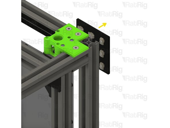
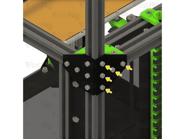
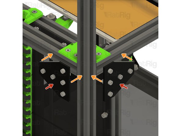
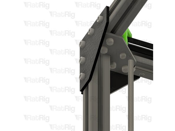
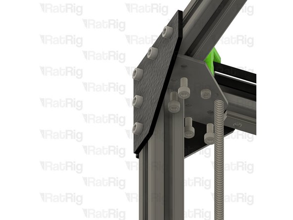
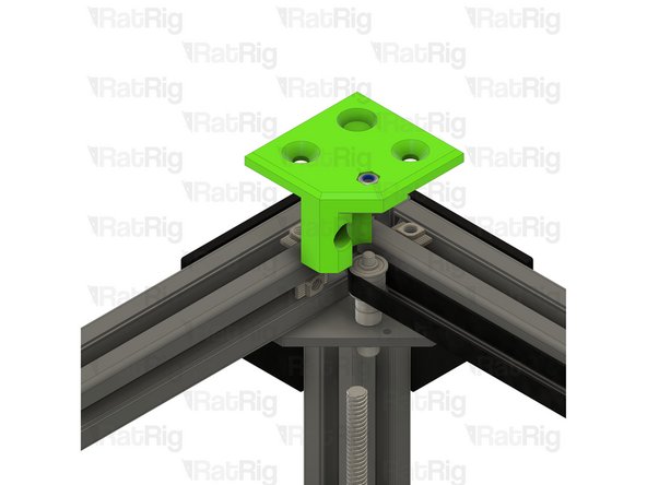
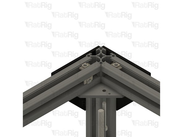
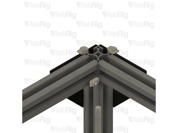
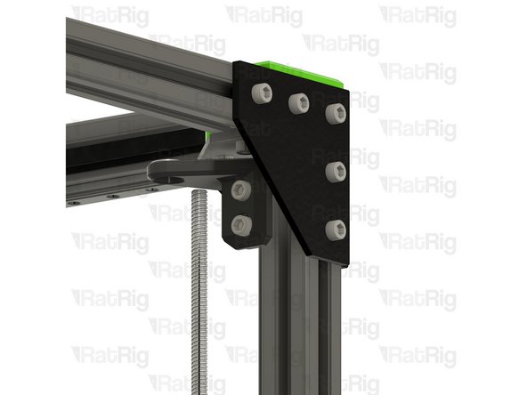
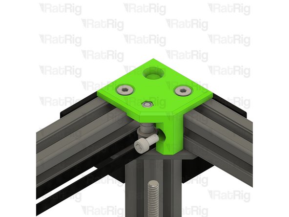
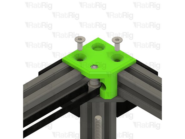
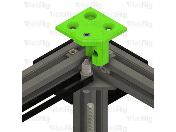
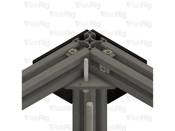
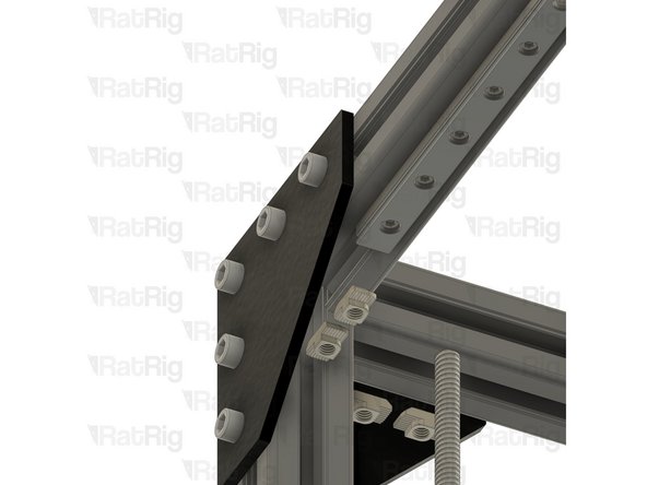
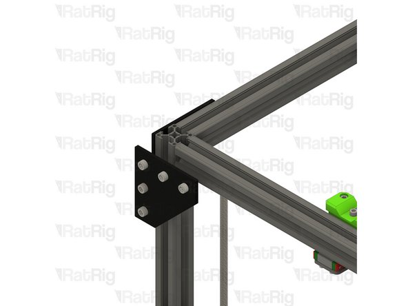
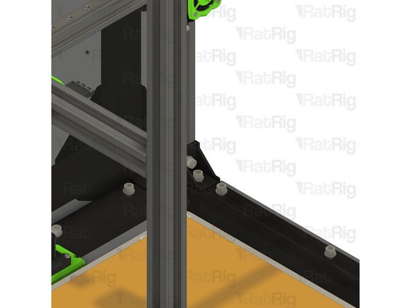
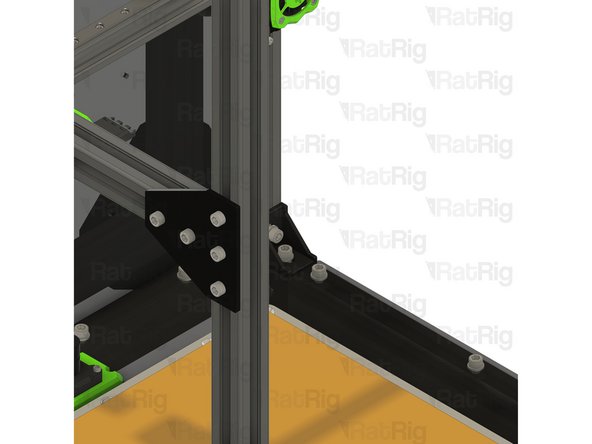
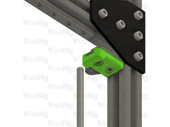
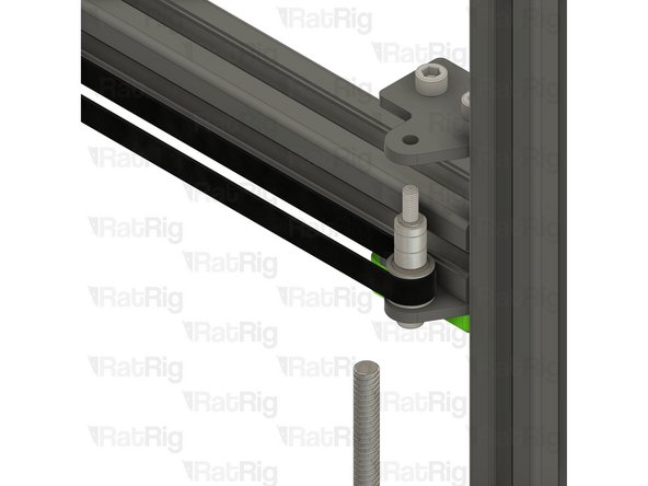
T-Shape plate assembly from Step 2
-
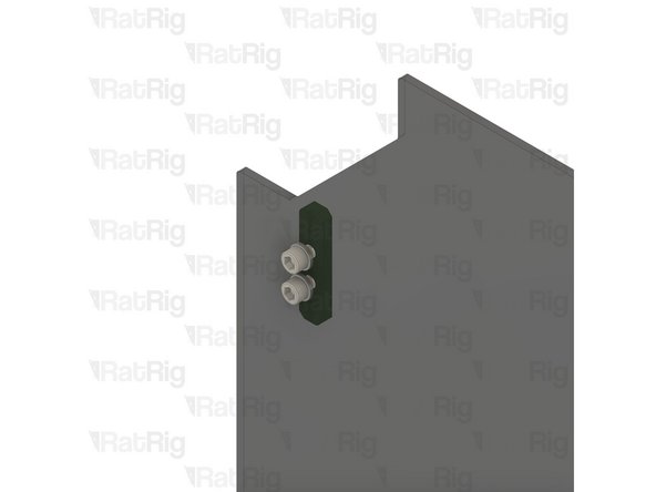
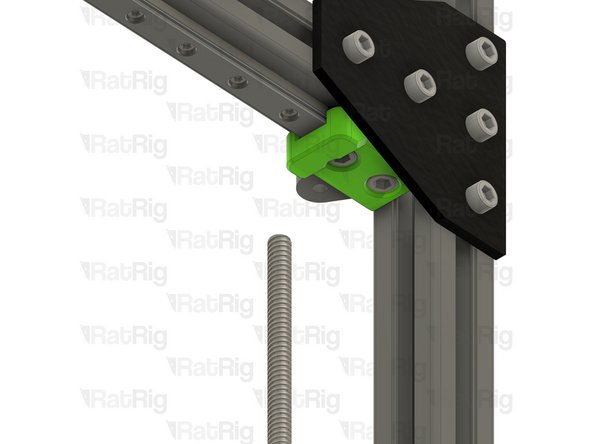
Position the T-shape plates as shown
-
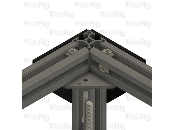
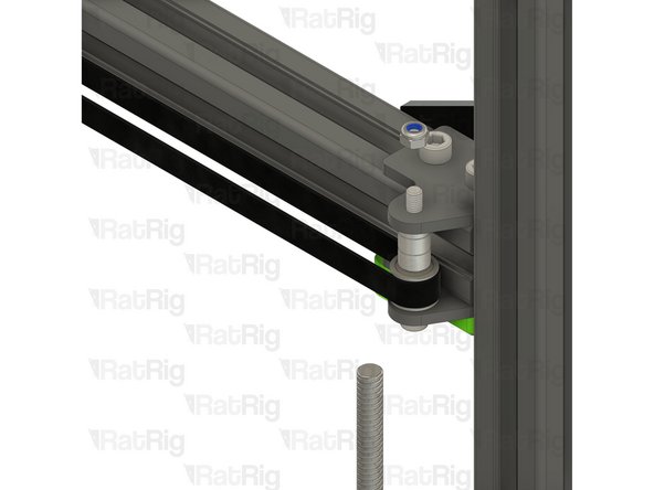
Secure the T-shape plates to the frame by fastening the five M6x12 screws
-
-
-
M6x12 Cap Head Screw
-
Loosen all of the M6x12 screws and remove both corner plate assemblies
-
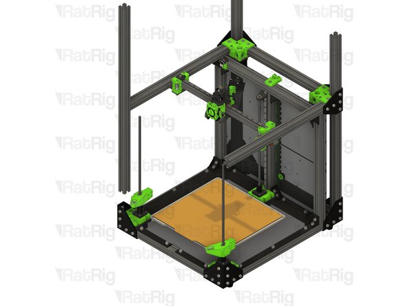
Loosen but do not remove the marked M6x12 screws
-
Pull the rear left 3030 extrusion upwards to remove it from the machine frame
-
Insert the 760mm 3030 extrusion into the bottom corner plate assemblies
-
You may need to rotate the 3030 t-nuts to insert the 3030 extrusion
-
Measure from the underside of the rear extrusion, to the top of the newly installed extrusion. It should measure either 230mm (for a V-Core 3 200) or 280mm (for a V-Core 300, 400 or 500)
-
Tighten the six marked M6x12 screws to secure the 3030 extrusion to the frame
-
-
-
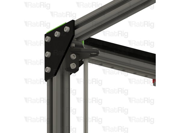
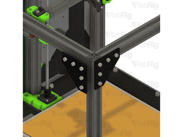
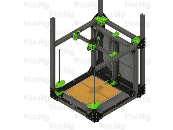
T-Shape plate assembly from Step 2
-
Position the T-shape plates as shown
-
Secure the T-shape plates to the frame by fastening the five M6x12 screws
-
-
-
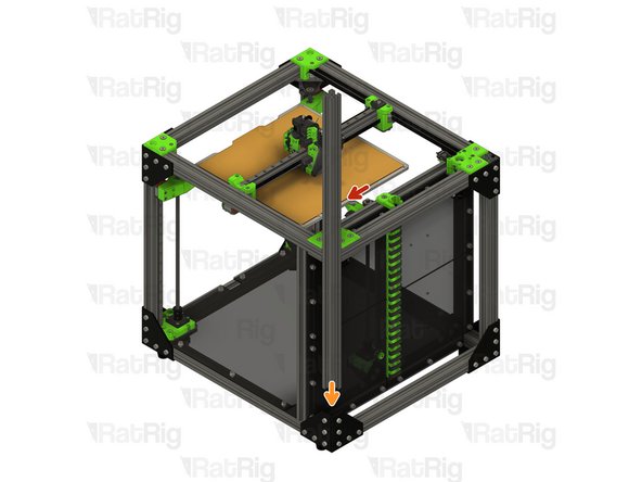
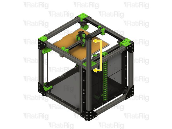
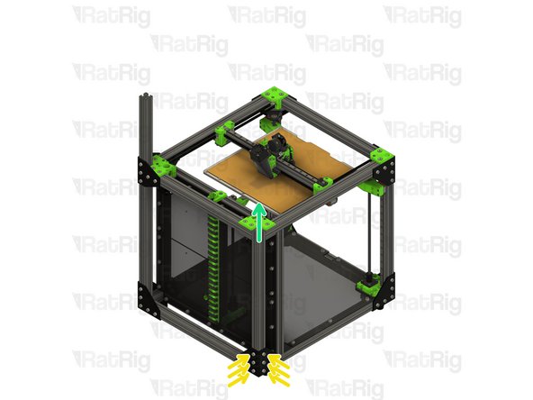
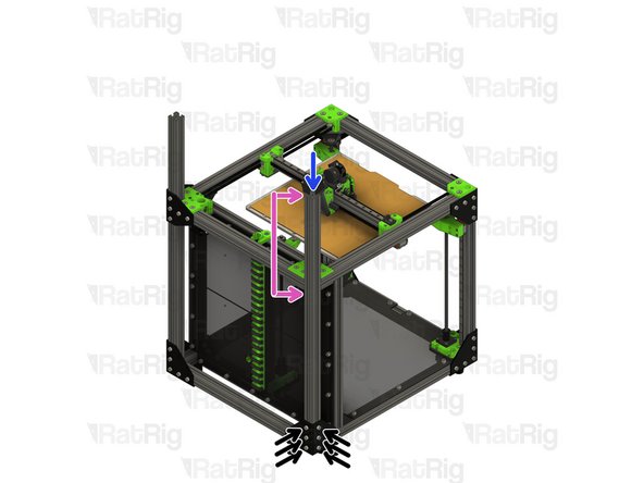
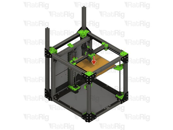
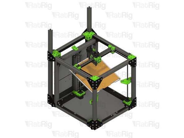
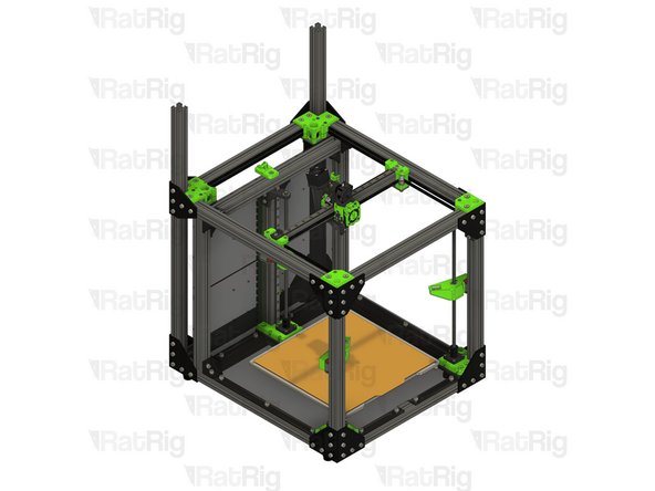
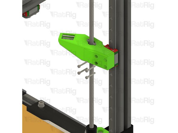
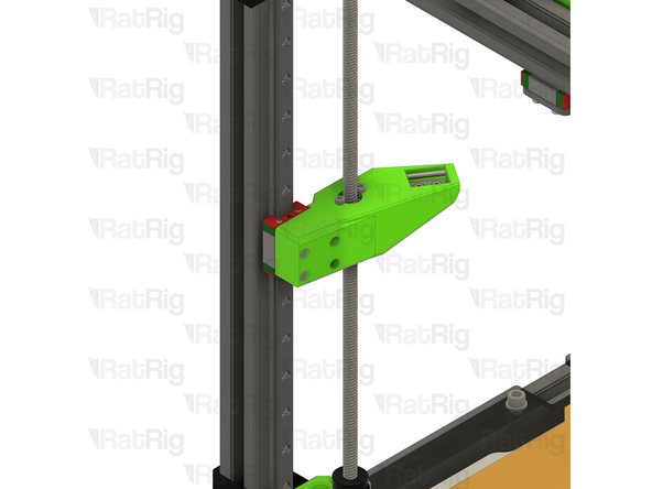
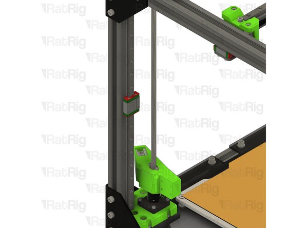
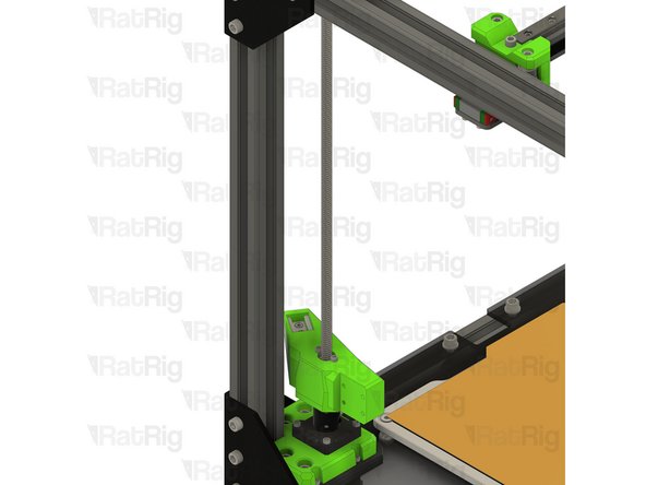
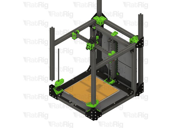
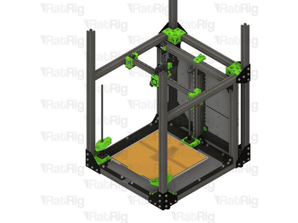
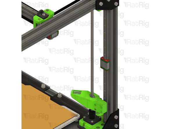
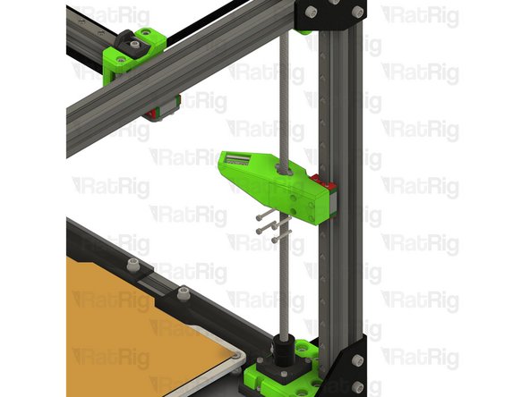
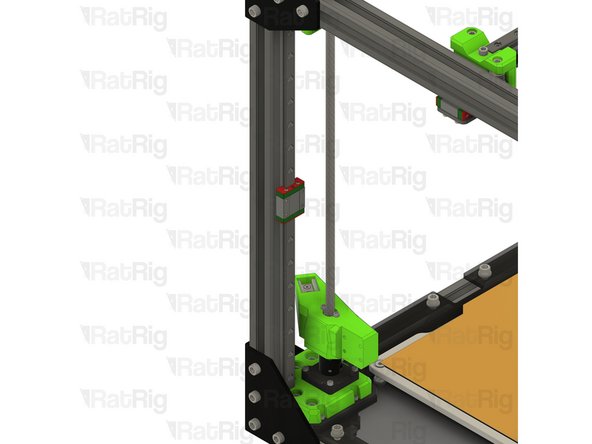
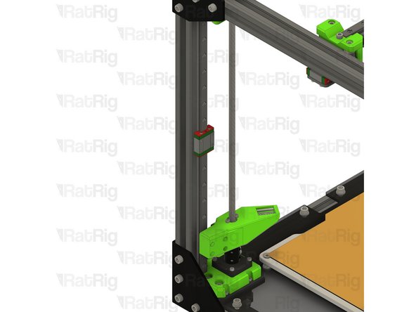
Print bed assembly
-
Lift the print bed assembly off of the bed arms and set it on the base panel (if installed), or the surface the printer sits on
-
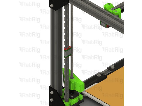
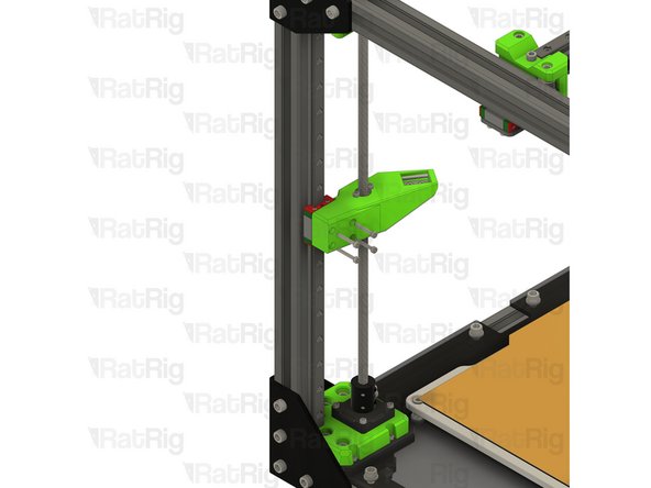
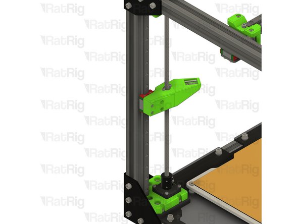
To lower the bed arms, you can manually rotate the leadscrews counter-clockwise
-
-
-
Insert wisdom here.
-
-
-
Insert wisdom here.
-
-
-
Insert wisdom here.
-
-
-
Insert wisdom here.
-
-
-
Insert wisdom here.
-
-
-
Insert wisdom here.
-
-
-
Insert wisdom here.
-
-
-
Insert wisdom here.
-
-
-
Insert wisdom here.
-
-
-
Insert wisdom here.
-
-
-
Insert wisdom here.
-
-
-
Insert wisdom here.
-
-
-
Insert wisdom here.
-
-
-
Insert wisdom here.
-
-
-
Insert wisdom here.
-
-
-
Insert wisdom here.
-
-
-
Insert wisdom here.
-
-
-
Insert wisdom here.
-
-
-
Insert wisdom here.
-
-
-
Insert wisdom here.
-
-
-
Insert wisdom here.
-
-
-
Insert wisdom here.
-
-
-
Insert wisdom here.
-
-
-
Insert wisdom here.
-
-
-
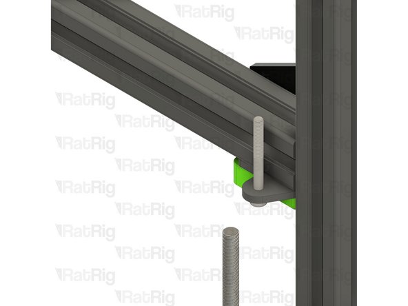
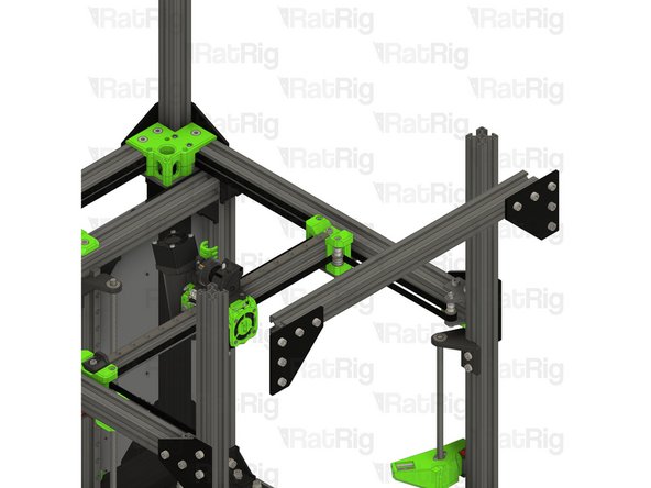
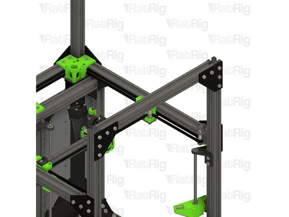
8x M6x12 Cap Head Screw
-
8x 3030 Drop-in T-Nut - M6
-
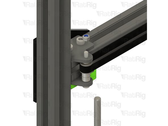
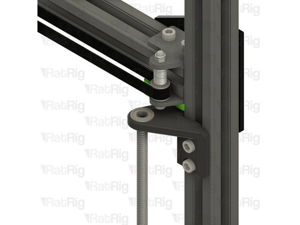
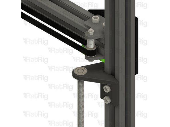
2x M5x45 Cap Head Screw
-
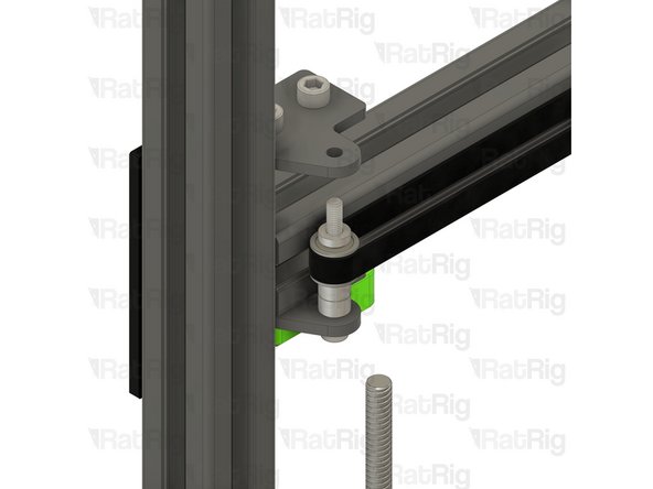
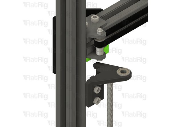
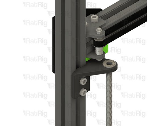
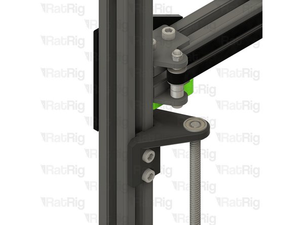
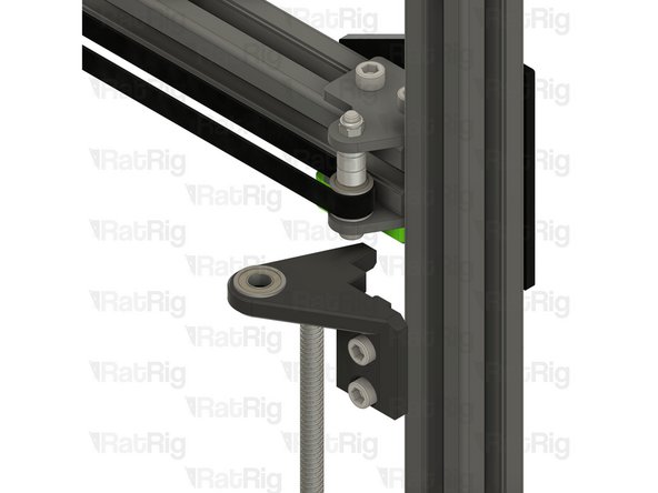
4x idler_plate_enclosure_2.0 plate
-
2x y_min_bumper printed part
-
2x M5 Nylon Locking Hex Nut
-
-
-
Insert wisdom here.
-
-
-
Insert wisdom here.
-
-
-
Insert wisdom here.
-
-
-
Insert wisdom here.
-
-
-
Insert wisdom here.
-
-
-
Insert wisdom here.
-
-
-
Insert wisdom here.
-
-
-
Insert wisdom here.
-
-
-
Insert wisdom here.
-
-
-
Insert wisdom here.
-
-
-
Insert wisdom here.
-
-
-
Insert wisdom here.
-
-
-
Insert wisdom here.
-
-
-
Insert wisdom here.
-
-
-
Insert wisdom here.
-
-
-
Insert wisdom here.
-
-
-
Insert wisdom here.
-