
Steps
22
- 02. WorkBench 2.0 - CNC Machines 22 steps

User-Contributed Guide
This guide is not managed by the site's staff.
Quiz
0
Introduction
To start the build, make sure you have a clean and empty working area dedicated to this assembly. This way, if you need to take a break, you don't have to move everything part way through the build. This decreases the risk of losing, or mismatching, components from the kit. Always have your tools close and organized in order to optimize your workflow. The steps in the build guide indicate what components are required and how many to use. In the step title there is a number, for example, (x2) means you have to repeat the step 2 times.
It is strongly recommended to assemble the kit on a known flat surface (such as a solid table, work surface or similar). Assembling the kit on a carpeted floor, or other non-flat surface, can cause the finished frame to not be square.
- The table top is not supplied, the user is meant to source it locally. A 20mm thick MDF board is recommended.
Table top dimensions (sourced by user):
- For StrongHold ONE 750x750 - Table: 1250x1250mm
- For StrongHold ONE 750x1250 - Table: 1250x1750mm
- For StrongHold ONE 1250x1250 - Table: 1750x1750mm
- For StrongHold PRO 1000x1000 - Table: 1500x1500mm
- For StrongHold PRO 1000x1500 - Table: 1500x2000mm
- For StrongHold PRO 1500x1500 - Table: 2000x2000mm
Please note: This guide is based upon building a 1500x1500 WorkBench 2.0 for the StrongHold Pro 1000x1000. Measurements for the different sizes of WorkBench 2.0 are provided in the relevant steps.
CAD Model:
Workbench 2.0 - 1500x1500: Fusion360 CAD Model
Workbench 2.0 - 1500x2000: Fusion360 CAD Model
Workbench 2.0 - 2000x2000: Fusion360 CAD Model
-
-
It is recommended to have the following tools available for assembling the WorkBench 2.0 for CNC Machines:
-
Allen Key 8mm
-
Tape measure
-
Engineers Square
-
-
-
12x 90 Degree Cast Corner
-
24x M8x16 Cap Head Screw
-
24x Drop-in T-Nut - M8
-
24x M8 Washer
-
-
-
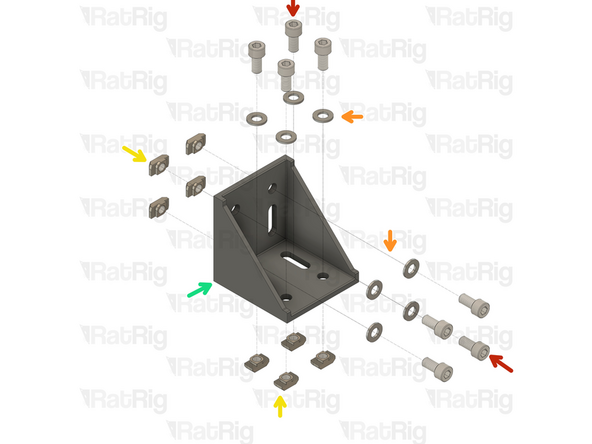
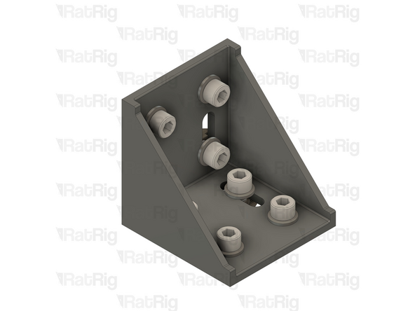
M8x16 Cap Head Screw
-
M8 Washer
-
4040 Drop-in T-Nut - M8
-
90 Degree Cast Corner
-
Loosely thread the 4040 T-Nuts on to the M8x16 screws. Do not tighten them at this point.
-
-
-
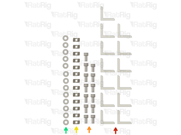
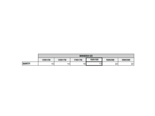
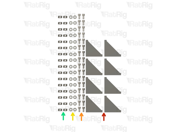
13x Simple 90 Degree Cast Corner
-
13x M8x16 Cap Head Screw
-
13x 4040 Drop-in T-Nut - M8
-
13x M8 Washer
-
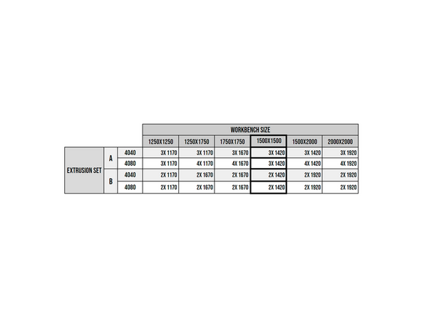
If you are building a different size WorkBench please consult the provided table for how many parts are required
-
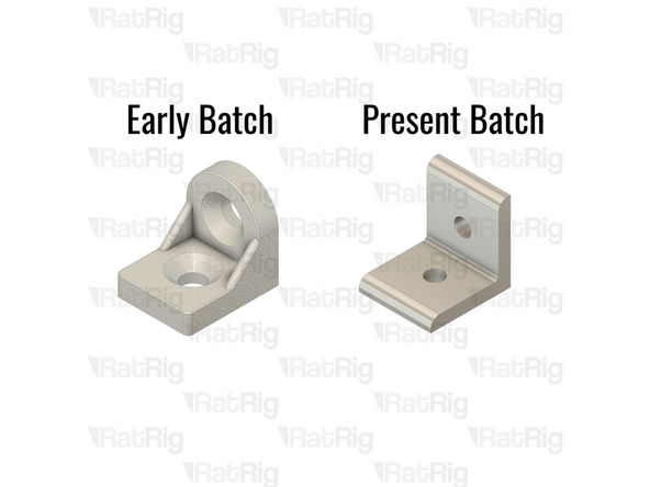
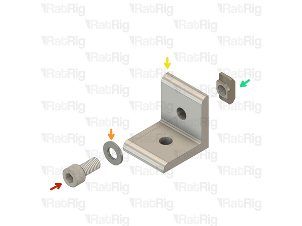
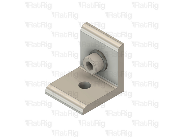
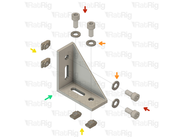
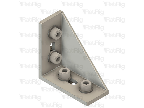
Early batches of the CNC Workbench 2.0 used a different 90 degree corner (shown in the third image), along with countersink hex head screws. The assembly instructions are identical regardless of the bracket and screw type used
-
-
-
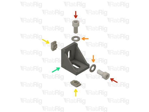
M8x16 Cap Head Screw
-
M8 Washer
-
Simple 90 Degree Cast Corner
-
4040 Drop-in T-Nut - M8
-
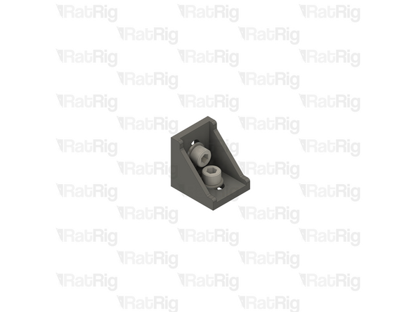
Loosely thread the 4040 T-Nuts on to the M8x16 screws. Do not tighten them at this point.
-
If you are building a different size WorkBench please consult the provided table for how many parts are required
-
-
-
8x Double 90 Degree Cast Corner
-
32x M8x16 Cap Head Screw
-
32x 4040 Drop-in T-Nut - M8
-
32x M8 Washer
-
-
-
8x M8x16 Cap Head Screw
-
8x M8 Washer
-
8x 4040 Drop-in T-Nut - M8
-
Double 90 Degree Cast Corner
-
Loosely thread the 4040 T-Nuts on to the M8x16 screws. Do not tighten them at this point.
-
-
-
8x Long 90 Degree Cast Corner
-
32x M8x16 Cap Head Screw
-
32x 4040 Drop-in T-Nut - M8
-
32x M8 Washer
-
-
-
4x M8x16 Cap Head Screw
-
4x M8 Washer
-
4x 4040 Drop-in T-Nut - M8
-
Long 90 Degree Cast Corner
-
Loosely thread the 4040 T-Nuts on to the M8x16 screws. Do not tighten them at this point.
-
-
-
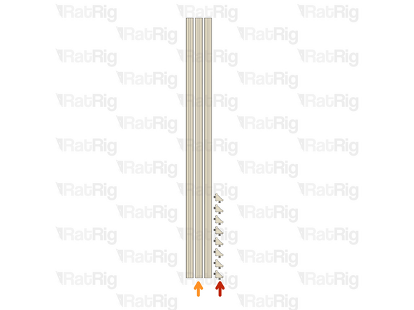
Consult the table and separate your extrusions in to 2 groups by length: A and B.
-
There are two types of extrusions regardless of their length: 4080 extrusions are used at the top of the WorkBench and the 4040 extrusions are part of the remaining frame.
-
All workbenches use the same 800mm long 4040 extrusions for the legs.
-
-
-
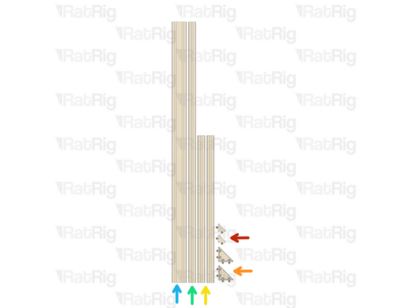
2x Cast Corners Assemblies
-
2x Long Cast Corners Assemblies
-
2x 800mm 4040 Extrusion
-
Set B - 1420mm 4040 Extrusion
-
Set B - 1420mm 4080 Extrusion
-
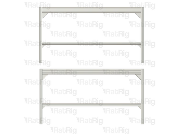
Assemble two side frames as shown.
-
Ensure the extrusions are flush and square with the cast corner assemblies before and after tightening the screws.
-
-
-
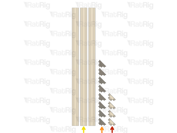
4x Long Cast Corner Assembly
-
8x Double Cast Corner Assembly
-
3x Set A -1420mm 4080 Extrusion
-
-
-
Complete one assembly if you are building:
-
StrongHold ONE 750x750 WorkBench 2.0
-
StrongHold PRO 1500x1500 WorkBench 2.0
-
Complete two assemblies if you are building any other WorkBench 2.0 size not mentioned above
-
Set A -1420mm 4080 Extrusion
-
4x Double Cast Corner
-
Check all of the cast corners to make sure they are flush with the extrusion ends
-
Secure the cast corners to the extrusion by fastening the sixteen M8x16 screws
-
-
-
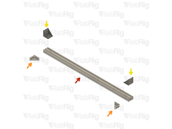
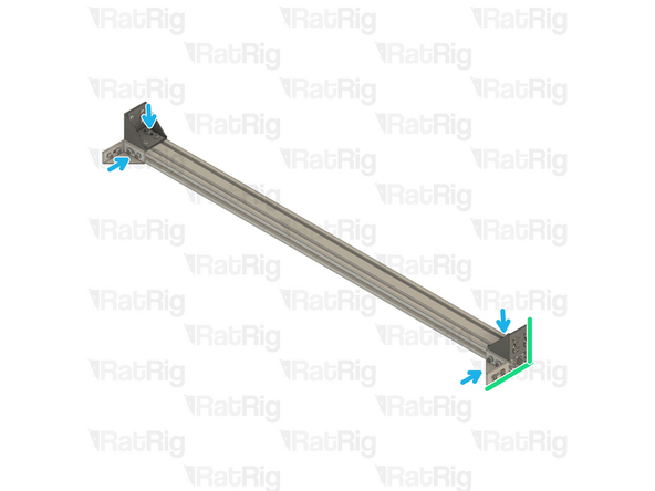
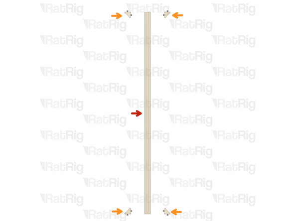
Set A - 1420mm 4080 Extrusion
-
2x Long Cast Corner
-
2x Double Cast Corner
-
Check all of the cast corners to make sure they are flush with the extrusion ends
-
Secure the cast corners to the extrusion by fastening the twelve M8x16 screws
-
Repeat this step to build the second assembly
-
-
-
8x Cast Corners assemblies
-
3x Set A -1420mm 4040 Extrusion
-
-
-
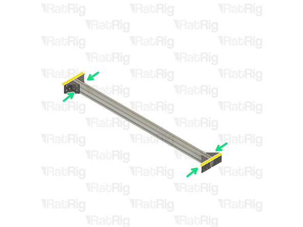
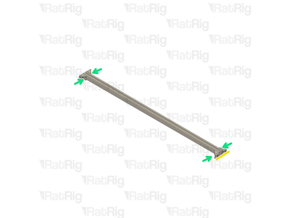
Set A- 1420mm 4080 Extrusion
-
4x Cast Corners Assembly
-
Check all of the cast corners to make sure they are flush with the extrusion ends
-
Secure the cast corners to the extrusion by fastening the four M8x16 screws
-
-
-
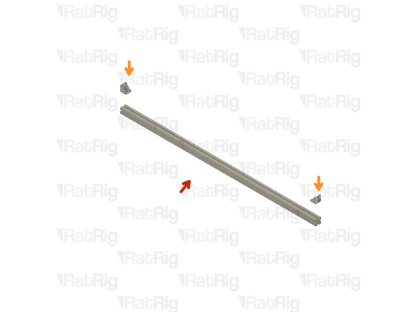
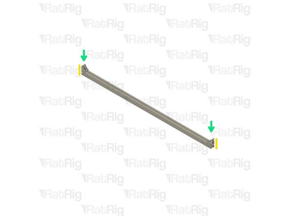
Set A - 1420mm 4040 Extrusion
-
2x Cast Corners Assembly
-
Check all of the cast corners to make sure they are flush with the extrusion ends
-
Secure the cast corners to the extrusion by fastening the four M8x16 screws
-
Repeat this step to build the second assembly
-
-
-
The next step depends on which WorkBench is being assembled:
-
Skip to Step 19 if you are building:
-
StrongHold ONE 750x750 WorkBench 2.0
-
StrongHold PRO 1500x1500 WorkBench 2.0
-
Skip to Step 20 if you are building:
-
Any other WorkBench 2.0 size not mentioned above
-
-
-
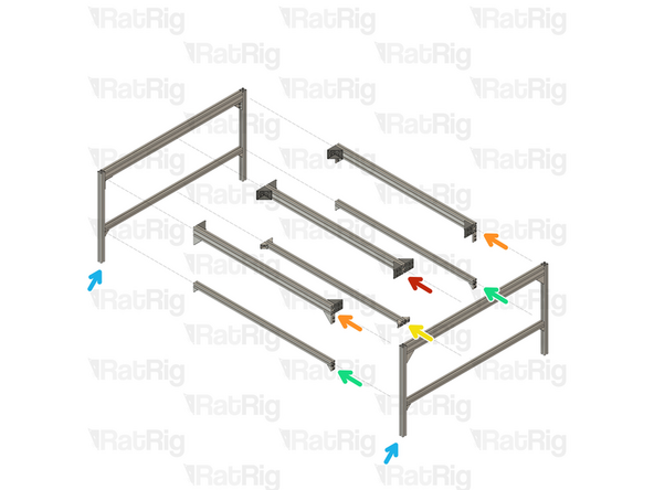
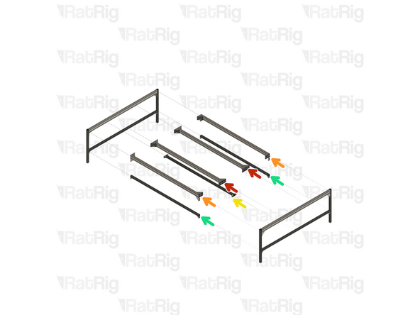
Top-Middle assembly from Step 13
-
Top-Side assemblies from Step 14
-
Bottom-Middle assemblies from Step 15
-
Bottom-Side assemblies from Step 17
-
Side frame assemblies from Step 11
-
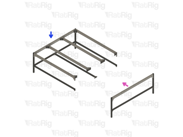
Attach the remaining extrusion assemblies to one of the side frames, as pictured, by fitting the t-nuts inside the slots and tightening the screws.
-
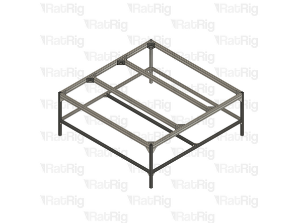
Attach the second side frame to the assembly.
-
Ensure the extrusions are flush and square with all cast corner assemblies before and after tightening the screws.
-
-
-
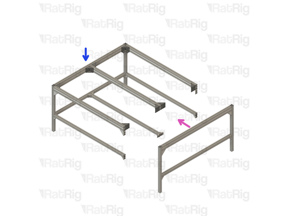
Top-Middle assemblies from Step 13
-
Top-Side assemblies from Step 14
-
Bottom-Middle assemblies from Step 15
-
Bottom-Side assemblies from Step 17
-
Side frame assemblies from Step 11
-
Attach the remaining extrusion assemblies to one of the side frames, as pictured, by fitting the t-nuts inside the slots and tightening the screws.
-
Attach the second side frame to the assembly.
-
Ensure the extrusions are flush and square with all cast corner assemblies before and after tightening the screws.
-
-
-
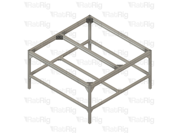
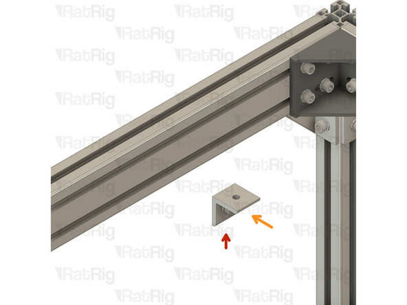
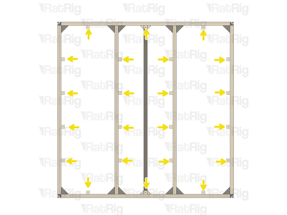
13x Simple Corner Assembly
-
Check Step 5 to see the number of simple corner brackets for you build size
-
If you are building a different size WorkBench 2.0, evenly distribute the simple corner assemblies.
-
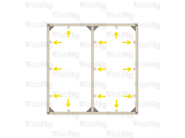
Mount the corner assembly on the frame top extrusion as shown
-
Repeat the steps above for the remaining corner assemblies. Position each corner roughly in the middle of the available space, as shown.
-
-
-
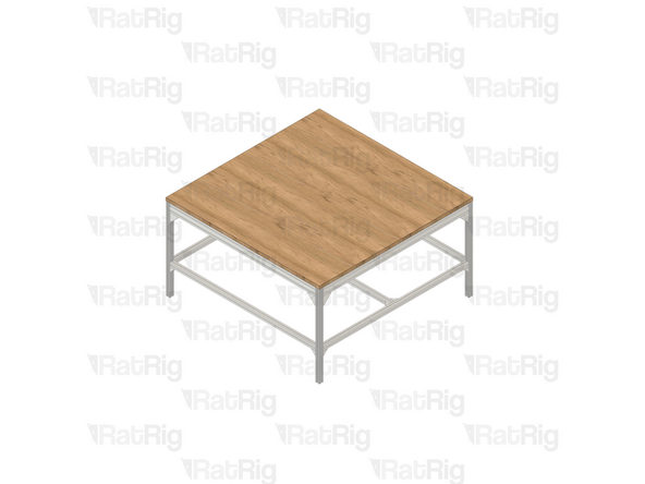
The table top is not included in the kit, you will have to source it locally. It is recommended to use a table top with a thickness no less than 20mm. The required dimensions are as follows:
-
StrongHold ONE 750x750 - Table: 1250x1250mm
-
StrongHold ONE 750x1250 - Table: 1250x1750mm
-
StrongHold ONE 1250x1250 - Table: 1750x1750mm
-
StrongHold PRO 1000x1000 - Table: 1500x1500mm
-
StrongHold PRO 1000x1500 - Table: 1500x2000mm
-
StrongHold PRO 1500x1500 - Table: 2000x2000mm
-


Cancel: I did not complete this guide.
One other person completed this guide.
