Steps
3
- 02. Z-Axis Assemblies 3 steps

In Progress
This guide is currently being written. Reload periodically to see the latest changes.

User-Contributed Guide
This guide is not managed by the site's staff.

Private
This guide will not appear in search results and can only be viewed by team members!
Quiz
0
-
-
2x lead_screw_motor_cage_front_3.1 printed part
-
2x Axial Thrust Bearing
-
2x pillow_block printed part
-
2x Rigid Lead Screw Coupler
-
2x 48mm NEMA17 Stepper Motor
-
-
-
8x M3x18 Cap Head Screw
-
8x M6x20 Cap Head Screw
-
8x 3030 Drop-in T-Nut - M6
-
8x M3 Nylon Locking Hex Nut
-
8x M3x12 Cap Head Screw
-
-
-
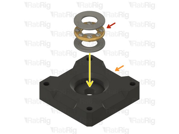
Axial Thrust Bearing
-
The axial thrust bearing has three components. Two end caps and an inner bearing assembly.
-
pillow_block printed part
-
Assemble the axial thrust bearing into the pillow_block as shown
-
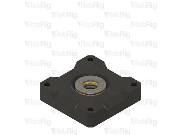
Make sure that the thrust bearing is fully inserted into the printed part. The top ring of the thrust bearing should be flush with the top of the pillow_block.
-
If desired, you may add a drop of light oil to the inner bearing assembly of the thrust bearing
-
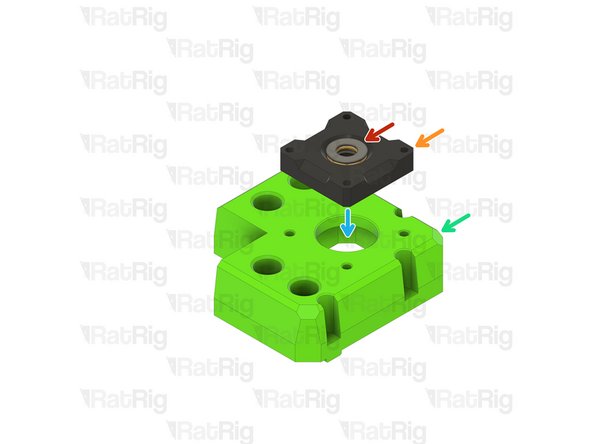
lead_screw_motor_cage_front_3.1 printed part
-
Place the pillow_block assembly atop the lead_screw_motor_cage_front_3.1 in preparation for the next step
-