Steps
8
- 03. Linear Rails 8 steps

User-Contributed Guide
This guide is not managed by the site's staff.
Quiz
0
Introduction
Please note: All measurements and component counts provided in this guide are based upon building a 300x300 V-Core 3.
If you are building a machine of a different size, please refer to the following list for the linear rail lengths, and required number of fasteners:
- 200x200: 2x 250mm, 3x 300mm, 56x M3x12 Screw, 56x 3030 T-Nuts
- 300x300: 2x 350mm, 3x 400mm, 76x M3x12 Screw, 76x 3030 T-Nuts
- 400x400: 2x 450mm, 3x 500mm, 96x M3x12 Screw, 96x 3030 T-Nuts
- 500x500: 2x 550mm, 3x 600mm, 116x M3x12 Screw, 116x 3030 T-Nuts
-
-
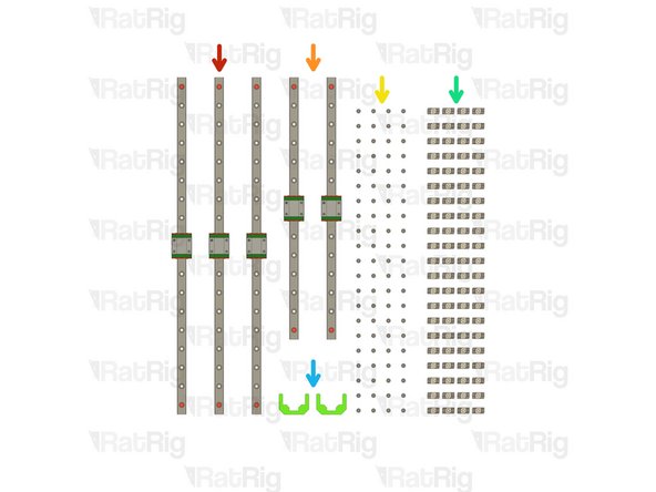
3x 400mm MGN12 Linear Rail
-
There will be a fourth rail of this length in the kit. Leave that one in its packaging until later
-
2x 350mm MGN12 Linear Rail
-
84x M3x12 Cap Head Screw
-
14x 3030 Drop-in T-Nut - M3
-
2x MGN12 3030 Alignment Tool
-
-
-
Paper Towels
-
The linear rails are supplied with a protective oil coating on them, so prepare your work surface with disposable and absorbent paper towels
-
Linear Rail
-
Carefully open one end of the linear rail packaging and remove the rail. Place the rail upon the paper towels and dispose of the packaging
-
Take a paper towel and carefully wipe the excess lubricant from the rail
-
-
-
With the rail still on the absorbent paper towels, carefully and slowly move the carriage from one end of the rail to the other
-
The carriage should move smoothly over the entire length of the rail
-
Small changes in resistance are normal, but the carriage becoming much harder to push, or binding completely are not
-
Repeat the previous test whilst applying a small amount of force downwards on the carriage
-
The carriage will likely travel more smoothly when applying a downwards force, this is normal
-
If the carriage does not move smoothly, or binds completely, refer to the Linear Rail Troubleshooting Guide
-
-
-
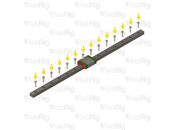
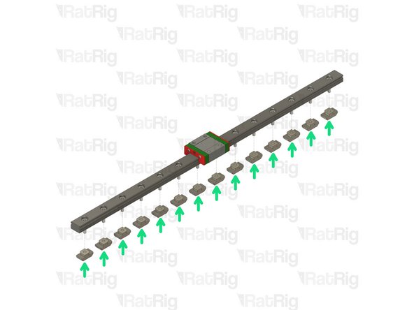
Linear Rail
-
Remove the plastic stops installed in the ends of the linear rail
-
Do not allow the linear rail carriage to leave the end of the rail
-
Insert an M3x12 screw in each of the holes on the linear rail
-
Loosely thread a 3030 T-Nut onto each of the M3x12 screws
-
Repeat these steps for the other 4 rails
-
-
-
V-Core 3.1 Frame Assembly
-
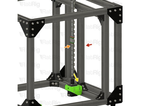
400mm MGN12 Linear Rail Assembly
-
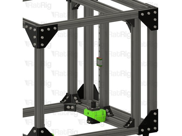
Insert the linear rail into the 3030 extrusion
-
The linear rail will rest on the lead screw motor cage
-
Install the two MGN12 3030 alignment tools as shown, this will make sure the linear rail is positioned correctly
-
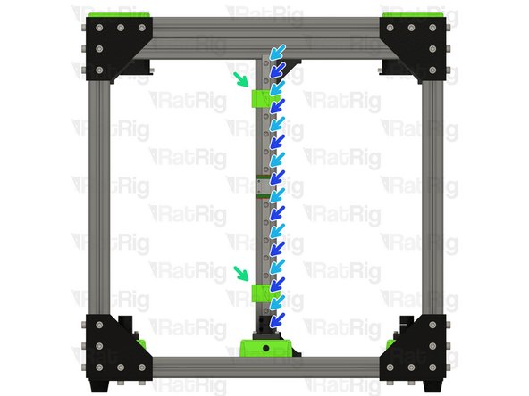
Fasten the marked M3x12 screws, starting from the bottom
-
Fasten the remaining M3x12 screws, starting at the bottom
-
Remove the MGN12 3030 alignment tools
-
-
-
400mm MGN12 Linear Rail Assembly
-
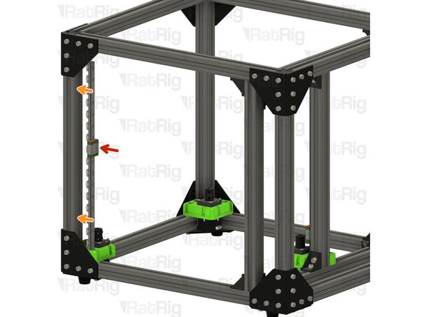
Insert the linear rail into the 3030 extrusion
-
The linear rail will rest on the front lead screw motor cage
-
Install the two MGN12 3030 alignment tools as shown, this will make sure the linear rail is positioned correctly
-
Fasten the marked M3x12 screws, starting from the bottom
-
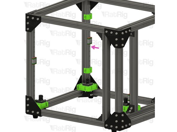
Fasten the remaining M3x12 screws, starting at the bottom
-
Remove the MGN12 3030 alignment tools
-
Repeat these steps for the linear rail on the opposite side
-
-
-
Installation of the Y-axis rails may be easier if you place the V-Core 3 frame upside down
-
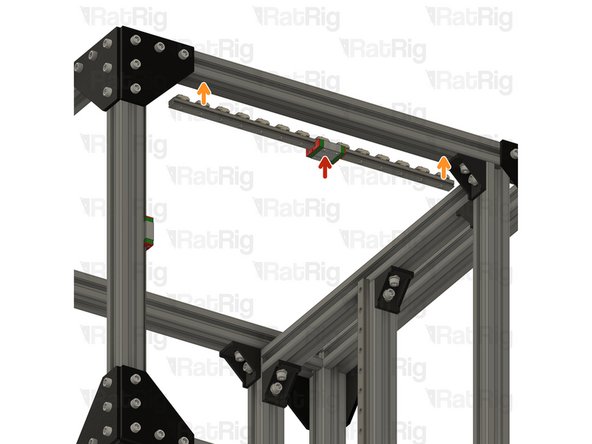
350mm MGN12 Linear Rail Assembly
-
Insert the linear rail into the 3030 extrusion
-
Position the linear rail so that its end touches the 3030 cast corner bracket as shown
-
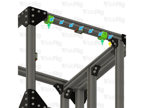
Install the two MGN12 3030 alignment tools as shown, this will make sure the linear rail is positioned correctly
-
Fasten the marked M3x12 screws, starting from one end
-
Fasten the remaining M3x12 screws
-
Remove the MGN12 3030 alignment tools and repeat these steps for the linear rail on the opposite side
-
-
-
Continue with the next guide: 04. CoreXY Idler Assemblies
-