-
-
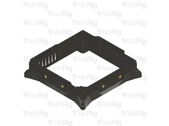
Rat_Pack_filter_cage_[Size]
-
Rat_Pack_blower_cage
-
8x Heat Insert M3
-
2x M4x12 CounterSink Screws
-
4x M3x12 Cap Head Screw
-
8x Heat Insert M4
-
Rat Pack Fan 120x32 blower 24V
-
-
-
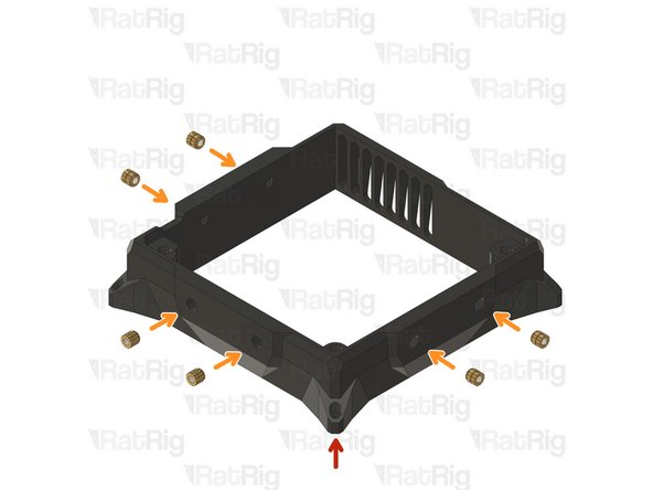
Rat_Pack_filter_cage_[Size]
-
The image shows the Rat_Pack_filet_cage_S but if you are assembling the Rat_Pack_filter_cage_L, install the same amount of heat inserts in the same places.
-
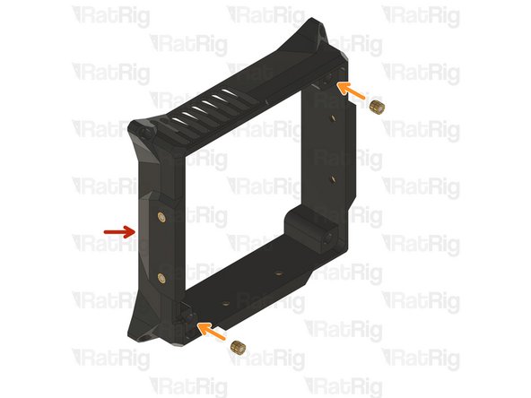
8x Heat Insert M3
-
-
-
Rat_Pack_blower_cage
-
The blower cage is the same for both Rat Pack sizes.
-
8x Heat Insert M4
-
-
-
Rat_Pack_filter_cage_[Size] with heat inserts
-
Rat_Pack_blower_cage with heat inserts
-
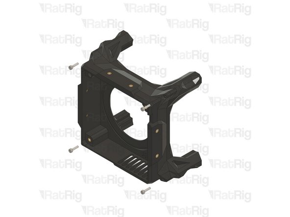
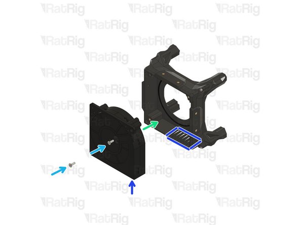
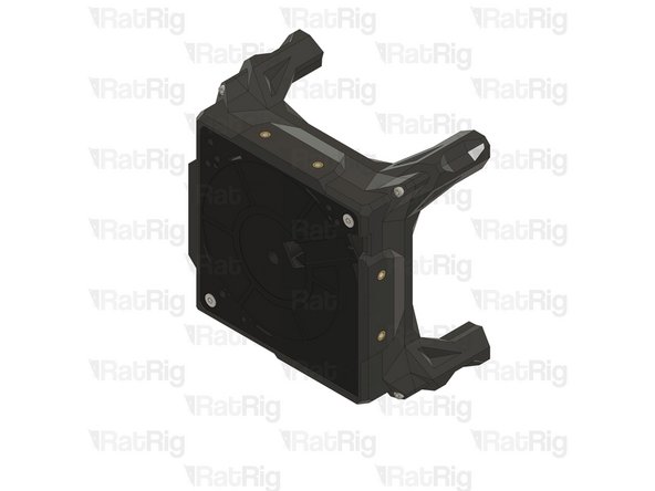
Ensure that the "Outlet" label on the Rat_Pack_filter_cage is aligned and faces the same direction as the fan exhaust grill on the Rat_Pack_blower_cage.
-
4x M3x12 Cap Head Screw
-
Take care not to over-tighten the screws as you can damage the printed parts
-
-
-
Rat Pack assembly
-
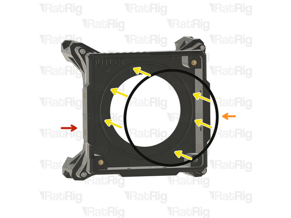
Rat Pack blower O-Ring - 106mm(OD) x 3mm(D)
-
Gently insert the O-Ring inside the designated groove.
-
The O-ring ensures optimal airflow by minimizing airflow losses.
-
Rat Pack Fan 120x32 blower 24V
-
2x M4x12 CounterSink Screws
-
Ensure that the fan's air outlet is directed towards the exhaust vent of the printed part.
-
-
-
Rat_Pack_Cover_[Size]
-
Rat Pack Filter [Size]
-
4x M3x12 Cap Head Screw
-
-
-
Rat Pack Assembly
-
Rat Pack Filter [Size]
-
Rat_Pack_Cover_[Size]
-
3x M3x12 Cap Head Screw
-
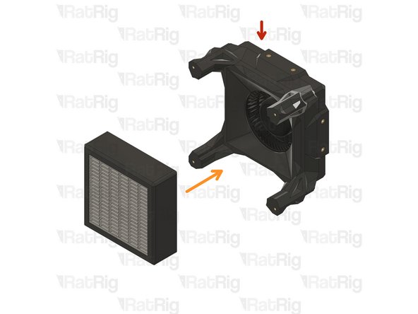
Take care not to over-tighten the screws as you can damage the printed parts
-
Carefully press the Rat Pack assembly inward to ensure a secure foam seal when the cover is installed.
-
-
-
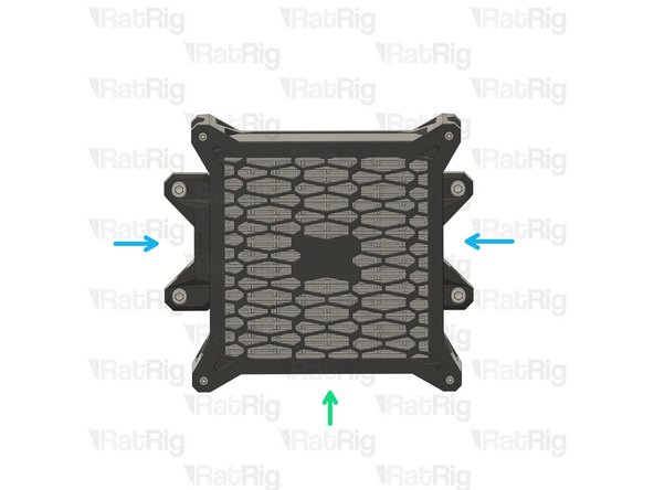
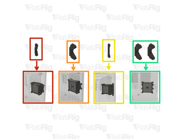
The Rat Pack offers several mounting options: it can be installed on the front of an extrusion, on the side, or directly onto a panel. Please select the mounting option you wish to proceed with:
-
The front extrusion mount 3030 is the standard configuration for the V-Core 4.
-
Front extrusion mount 3030 [Size S]
-
Front extrusion mount 3030 [Size L]
-
Side extrusion mount 3030 [Both Sizes]
-
Panel mount [Both sizes]
-
This option requires drilling mounting holes into the panel.
-
-
-
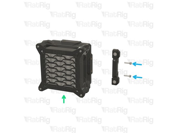
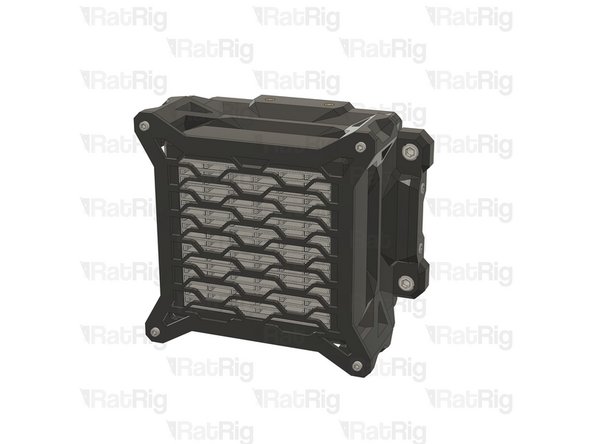
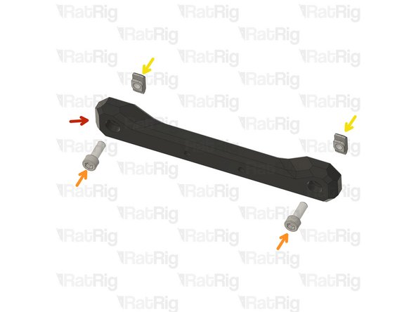
Rat_Pack_Mount_[Size]
-
The mount shown in the pictures is size S; the procedure is the same for size L.
-
2x M6x16 Cap Head Screw
-
2x 3030 Drop-in T-Nut - M6
-
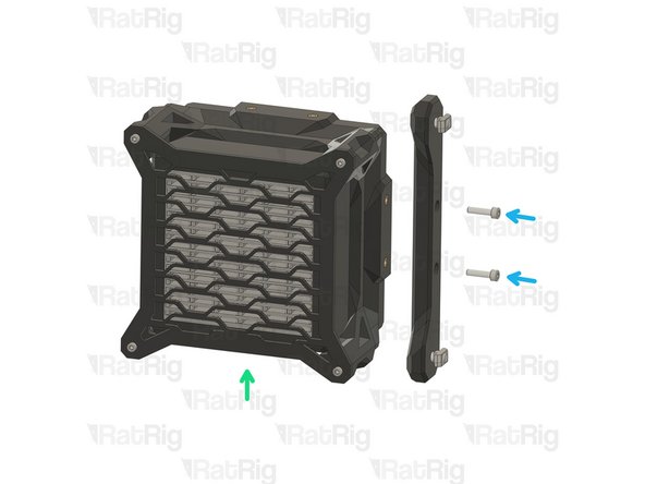
Rat Pack Assembly
-
Ensure that the air outlet is directed towards the bottom.
-
2x M4x16 Cap Head Screws
-
-
-
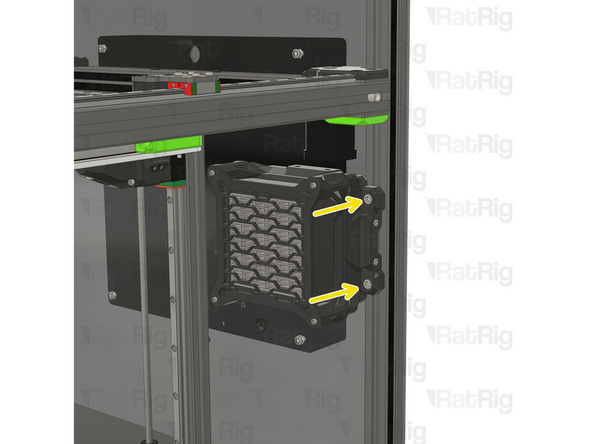
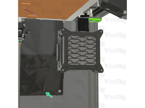
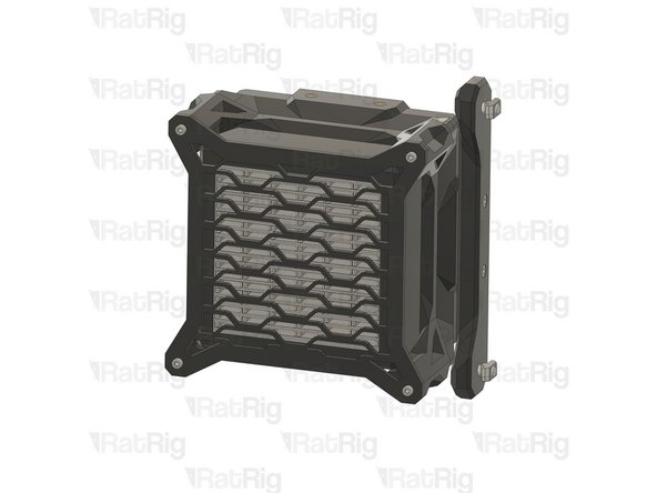
Rat Pack assembly [Size]
-
Install the Rat Pack onto the rear 3030 extrusion
-
When installing the Rat Pack on an IDEX machine, take extra care to avoid pinching the PTFE tube for the T1 filament. Pinching the tube can obstruct filament flow and compromise print quality, so ensure it is routed smoothly and without any pressure points.
-
Tighten the M6 screws on the Rat Pack
-
Route the wires through the same hole as the bed cables
-
-
-
Rat_Pack_Mount_Side
-
2x M6x16 Cap Head Screw
-
2x 3030 Drop-in T-Nut - M6
-
Rat Pack Assembly
-
Ensure that the air outlet is directed towards the bottom.
-
2x M4x16 Cap Head Screws
-
-
-
You will need to source M4x16 cap head screws and an additional screw of your choice for panel mounting. Please consider your panel's thickness when selecting the appropriate screw length.
-
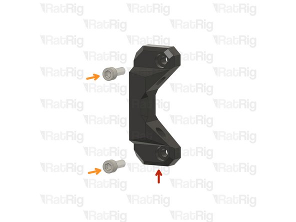
2x Rat_Pack_Mount_[Size]
-
The mount shown in the pictures is size L; the procedure is the same for size S.
-
2x Screw of your choice to mount on the panel (M6 is recommended)
-
2x M4x16 Cap Head Screws
-
Repeat the previous Steps and assemble another Rat Pack Mount
-
-
-
Rat Pack blower
-
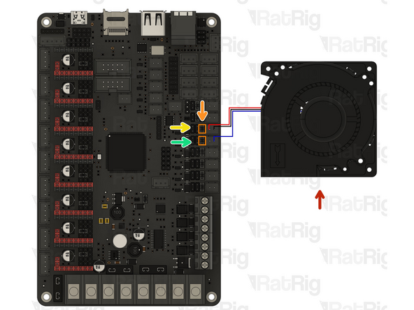
Ensure that the jumpers are configured as shown, as this setting adjusts the ports to 24V.
-
The Octopus V1.1 is the standard control board for the V-Core 4. If you are using a different control board, please consult its datasheet to determine the correct port configuration.
-
Connect the RED (+24V) and BLACK (GND) wires as shown.
-
Connect the BLUE (PWM) wire as shown.
-
-
-
The Octopus V1.1 is the standard control board for the V-Core 4. If you are using a different control board, please consult its datasheet to determine the correct port configuration.
-
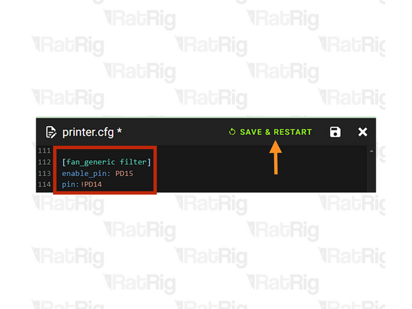
Add the following config at the bottom of your printer.cfg file:
-
[fan_generic filter]
-
enable_pin: PD15
-
pin: !PD14
-
Click on "SAVE & RESTART" to confirm the changes, klipper will reboot with the new configuration.
-
You can find more information on the Rat Pack config here
-
-
-
The Rat Pack chamber filter is now fully operational. It will activate automatically at the start of each print job and continue running for 300 seconds after the print is complete, ensuring the air inside the machine is thoroughly filtered before it is opened.
-
Cancel: I did not complete this guide.
2 other people completed this guide.

![Rat_Pack_filter_cage_[Size]](https://d3t0tbmlie281e.cloudfront.net/igi/ratrig/iAKelMRLnFCDUrQL.medium)
![Rat_Pack_filter_cage_[Size]](https://d3t0tbmlie281e.cloudfront.net/igi/ratrig/wGSUl5RLNIChA1wj.medium)


![Rat_Pack_filter_cage_[Size] with heat inserts](https://d3t0tbmlie281e.cloudfront.net/igi/ratrig/F6CR5FRLrvClDdvK.medium)
![Rat_Pack_Cover_[Size]](https://d3t0tbmlie281e.cloudfront.net/igi/ratrig/y4IqlORLW4ClDdvK.medium)
![Rat Pack Filter [Size]](https://d3t0tbmlie281e.cloudfront.net/igi/ratrig/iZ5E5HRLJHCJkYKk.medium)
![Rat_Pack_Cover_[Size]](https://d3t0tbmlie281e.cloudfront.net/igi/ratrig/Hr1ylfRLehqtwwyu.medium)
![Rat_Pack_Mount_[Size]](https://d3t0tbmlie281e.cloudfront.net/igi/ratrig/Ck4nl6RL5QCJkajy.medium)
![Rat Pack assembly [Size]](https://d3t0tbmlie281e.cloudfront.net/igi/ratrig/a6eCohRLShqtwwyu.medium)
![2x Rat_Pack_Mount_[Size]](https://d3t0tbmlie281e.cloudfront.net/igi/ratrig/jpAqlaRLQgCJkajy.medium)
