-
-
4x Rat Rig StrongHold PRO CNC - HG25 Spacer Plate 3mm
-
16x M6x22 Cap Head Screw
-
16x M6 Washer
-
8x M5x20 Cap Head Screw
-
8x M5 Washer
-
4x sh_pro_x-gantry_tool Printed Part
-
-
-
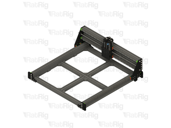
StrongHold PRO Base Assembly - Rear Left Corner
-
sh_pro_x-gantry_tool Printed Part
-
Position each pair of X-gantry tools as shown
-
The rear tool should rest against the motor plate
-
The front tool should be placed facing the rear one, and spaced so there is roughly a 20mm gap between the tools
-
Repeat these instructions to position the second set of tools on the other side of the base assembly
-
-
-
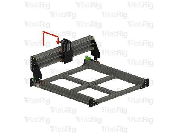
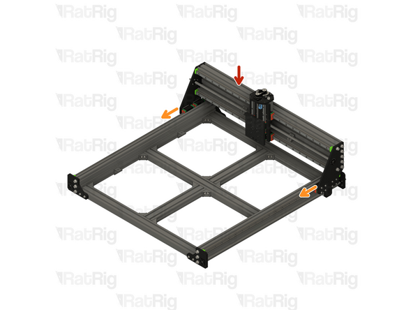
It is highly recommended to have two or more people for the next few steps in particular
-
The X-axis gantry is large and heavy and can cause injury if it were to fall
-
The printed parts are designed to support the weight of the X-axis gantry, but they will not prevent it moving or tipping
-
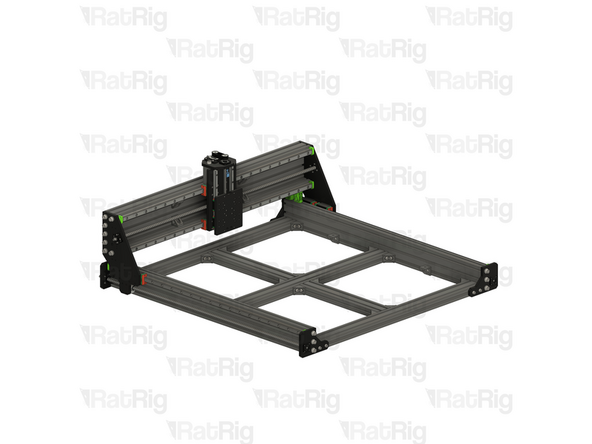
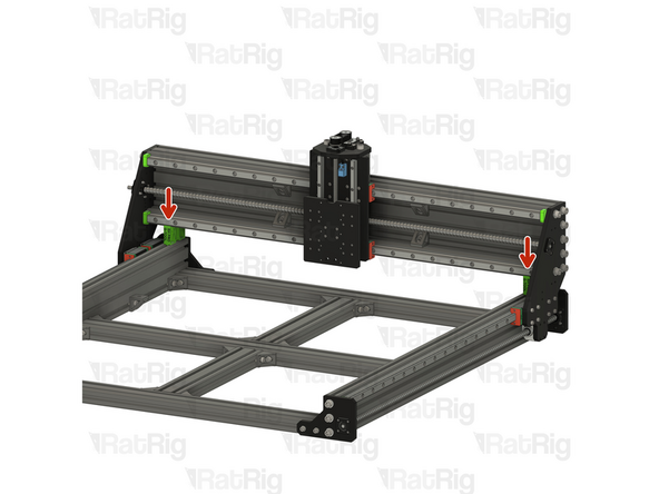
Lift the X-axis gantry assembly up and slowly lower it in to position on top of the printed tools as shown
-
When lowering the X-axis gantry, make sure the plates at either end do not collide with the linear rail carriages or the ball screw components
-
Continue to support the X-axis gantry as it may tip forwards or backwards until secured
-
-
-
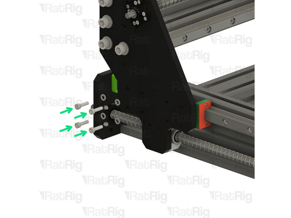
At least one other person should continue to support the X-axis gantry during this step
-
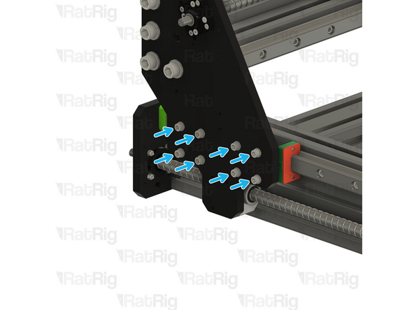
Align one of the HG25 linear rail carriages with the holes on the X-axis gantry plate
-
Rat Rig StrongHold PRO CNC - HG25 Spacer Plate 3mm
-
Insert the spacer from below. It will fit in the gap between the linear rail carriage and the X-axis gantry plate
-
M6x22 Cap Head Screw & M6 Washer
-
Install an M6 washer on to each of the M6x22 screws, then insert them through the X-axis gantry plate, the HG25 spacer plate, and screw them into the HG25 linear rail carriage
-
Do not fully tighten the M6x22 screws yet
-
-
-
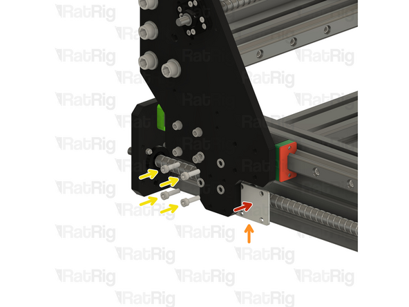
At least one other person should continue to support the X-axis gantry during this step
-
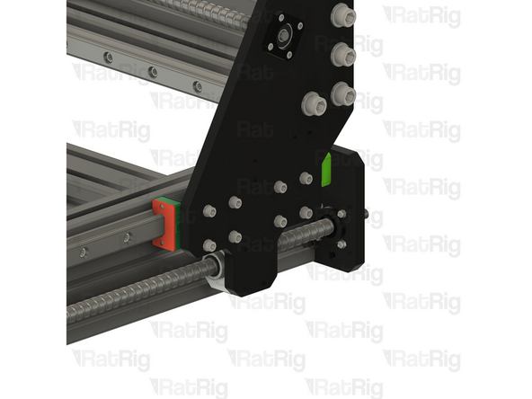
Align the second HG25 linear rail carriage with the holes on the X-axis gantry plate
-
Rat Rig StrongHold PRO CNC - HG25 Spacer Plate 3mm
-
Insert the spacer from below. It will fit in the gap between the linear rail carriage and the X-axis gantry plate
-
M6x22 Cap Head Screw & M6 Washer
-
Install an M6 washer on to each of the M6x22 screws, then insert them through the X-axis gantry plate, the HG25 spacer plate, and screw them into the HG25 linear rail carriage
-
Tighten all eight M6x22 screws
-
-
-
At least one other person should continue to support the X-axis gantry during this step
-
Repeat Steps 4 & 5 to secure the right side of the X-axis gantry to the base
-
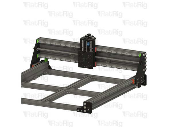
Once all sixteen M6x22 screws are fully tightened, the X-axis gantry no longer needs to be supported
-
-
-
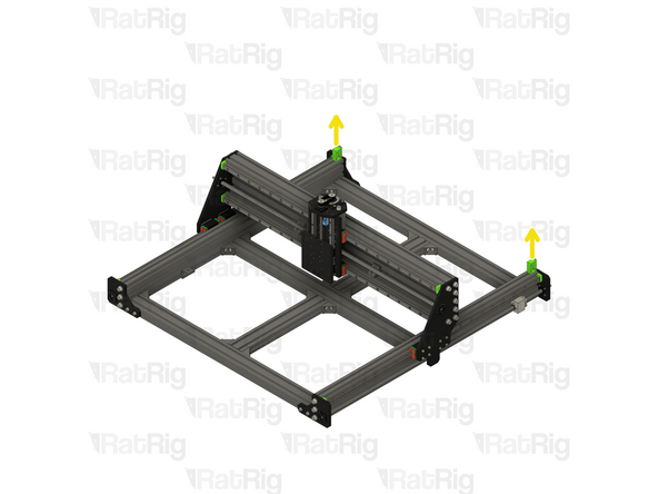
sh_pro_x-gantry_tool Printed Part
-
Carefully remove the front two X-axis gantry tools from the assembly
-
The tools may require a small amount of force to remove
-
-
-
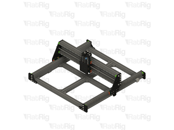
StrongHold PRO X-Axis Gantry Assembly
-
Carefully push the X-axis gantry towards the front of the machine. Once the X-axis gantry tools are no longer between the gantry and the base, it should move smoothly
-
Remove the remaining two X-axis gantry tools
-
-
-
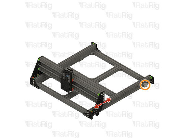
Slowly and carefully move the X-axis gantry over the full length of the axis
-
Be mindful of the ball screw blocks, do not allow the gantry to collide with them!
-
-
-
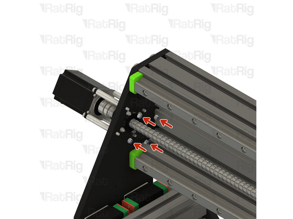
1610 Ball Screw
-
Rotate the ball screw by hand to align the ball screw block with the matching holes in the X-axis gantry
-
Once all four holes are aligned, install an M5 washer on to each M5x20 screw and insert them through the gantry plate, screwing them into the ball screw block
-
After all four M5x20 screws are installed, fully tighten them
-
Repeat these instructions to secure the ball screw block to the other side of the X-axis gantry
-
-
-
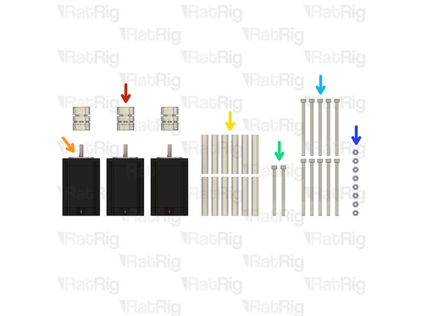
3x Disc Coupler
-
3x NEMA23 Stepper Motor
-
12x 58mm Aluminium Spacer
-
2x M5x70 Cap Head Screw
-
10x M5x80 Cap Head Screw
-
8x M5 Nylon Locking Hex Nut
-
-
-
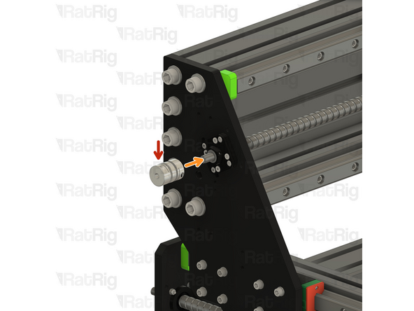
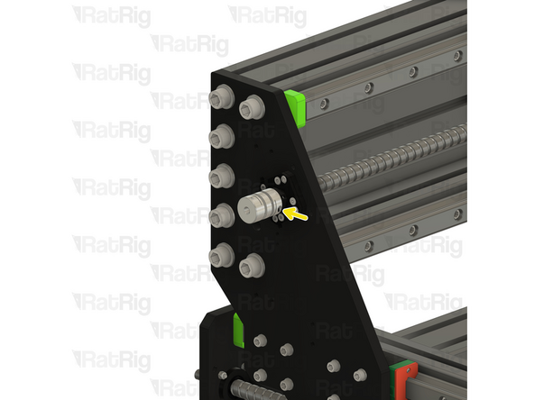
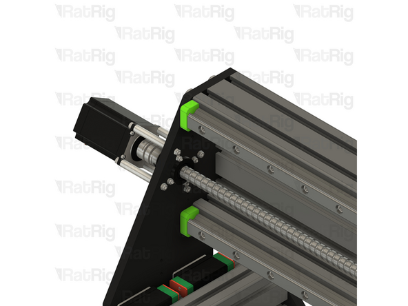
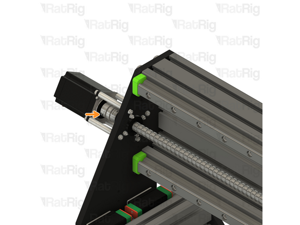
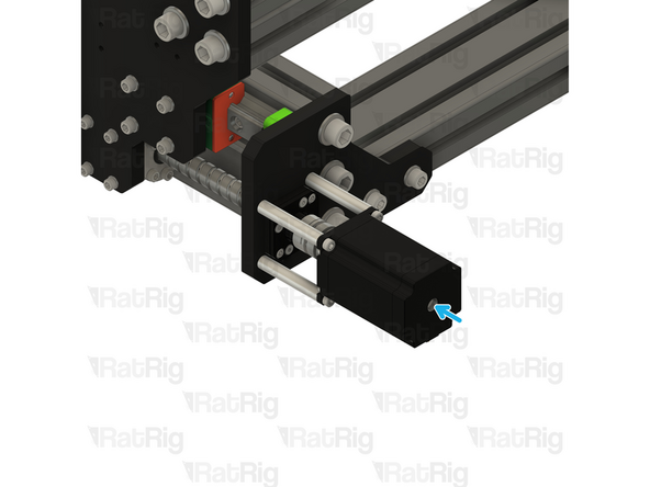
Disc Coupler
-
Install the disc coupler on to the end of the 1610 ball screw shaft
-
Using a 2.5mm hex key, tighten the marked screw to secure the disc coupler to the shaft
-
-
-
M5x80 Cap Head Screw
-
NEMA23 Stepper Motor
-
58mm Aluminium Spacer
-
Insert one M5x80 screw through each hole on the NEMA23 stepper motor
-
Install one aluminium spacer on to each M5x80 screw
-
Install the NEMA23 assembly on to the X-axis gantry. All four M5x80 screws should pass through the plate and the NEMA23 shaft should fit into the disc coupler
-
Continue to support the NEMA23 assembly until it is secured in the next step
-
-
-
M5 Nylon Locking Hex Nut
-
Install an M5 nylon locking hex nut on to each exposed M5x80 screw
-
Fully tighten all four M5x80 screws to secure the NEMA23 stepper motor to the X-axis gantry
-
Rotate the ball screw by hand until the marked screw is accessible
-
Using a 2.5mm hex key, tighten the marked screw to secure the disc coupler to the NEMA23 shaft
-
-
-
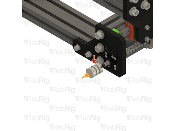
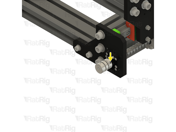
Disc Coupler
-
Install the disc coupler on to the end of the 1610 ball screw shaft
-
Using a 2.5mm hex key, tighten the marked screw to secure the disc coupler to the shaft
-
-
-
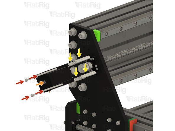
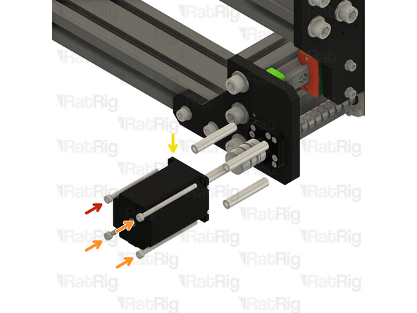
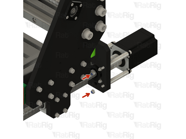
M5x70 Cap Head Screw
-
M5x80 Cap Head Screw
-
NEMA23 Stepper Motor
-
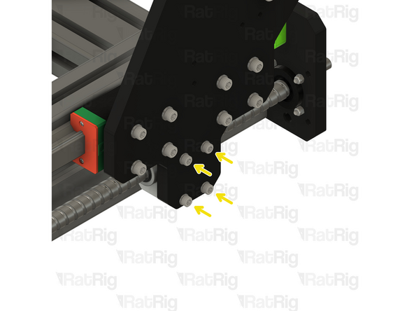
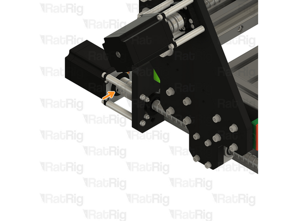
Insert the M5x70 screw through the marked hole on the NEMA23 stepper motor
-
Insert one M5x80 screw through each remaining hole on the NEMA23 stepper motor
-
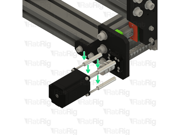
58mm Aluminium Spacer
-
Install the NEMA23 assembly on to the Y-axis plate
-
The M5x70 screw will thread into the motor plate and the M5x80 screw below the M5x70 screw will thread into the existing M5 hex nut. The remaining two M5x80 screws will pass through the motor plate. The NEMA23 shaft should fit into the disc coupler
-
-
-
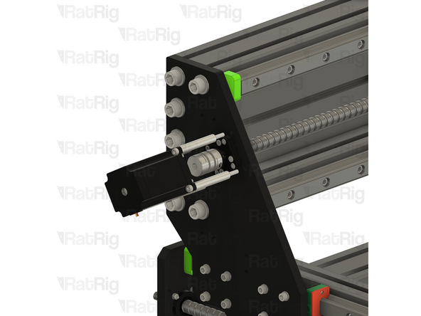
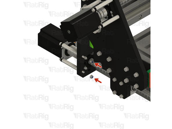
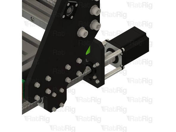
M5 Nylon Locking Hex Nut
-
Install an M5 nylon locking hex nut on to each exposed M5x80 screw
-
Fully tighten the M5x70 and all three M5x80 screws to secure the NEMA23 stepper motor to the motor plate
-
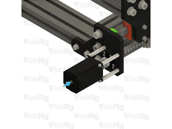
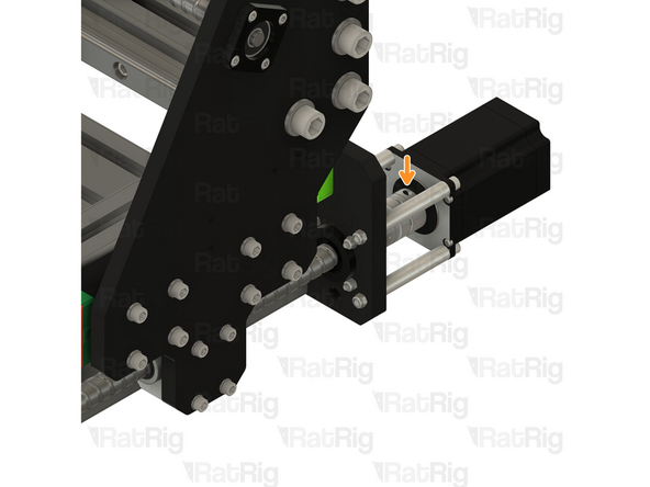
Rotate the ball screw by hand until the marked screw is accessible
-
You will need to rotate both Y-axis ball screws together, otherwise the X-axis gantry can twist
-
Using a 2.5mm hex key, tighten the marked screw to secure the disc coupler to the NEMA23 shaft
-
-
-
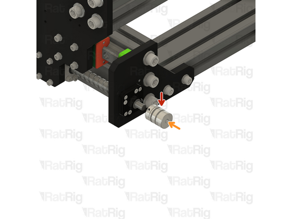
Disc Coupler
-
Install the disc coupler on to the end of the 1610 ball screw shaft
-
Using a 2.5mm hex key, tighten the marked screw to secure the disc coupler to the shaft
-
-
-
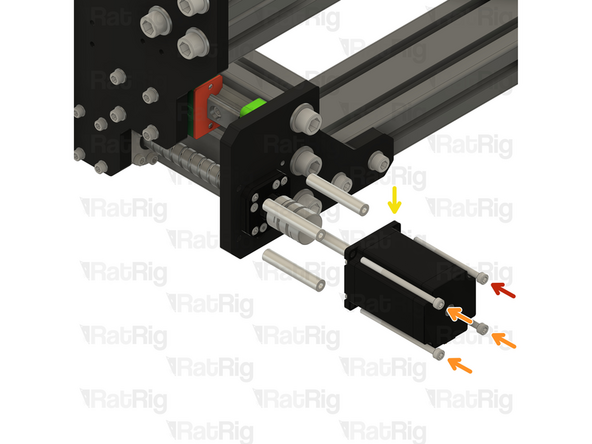
M5x70 Cap Head Screw
-
M5x80 Cap Head Screw
-
NEMA23 Stepper Motor
-
Insert the M5x70 screw through the marked hole on the NEMA23 stepper motor
-
Insert one M5x80 screw through each remaining hole on the NEMA23 stepper motor
-
58mm Aluminium Spacer
-
Install the NEMA23 assembly on to the Y-axis plate
-
The M5x70 screw will thread into the motor plate and the M5x80 screw below the M5x70 screw will thread into the existing M5 hex nut. The remaining two M5x80 screws will pass through the motor plate. The NEMA23 shaft should fit into the disc coupler
-
-
-
M5 Nylon Locking Hex Nut
-
Install an M5 nylon locking hex nut on to each exposed M5x80 screw
-
Fully tighten the M5x70 and all three M5x80 screws to secure the NEMA23 stepper motor to the motor plate
-
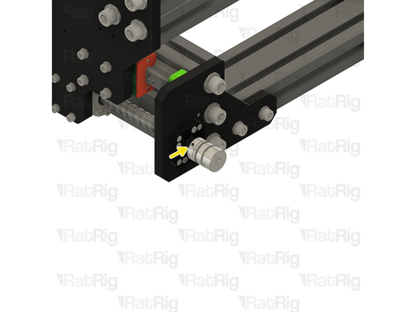
Rotate the ball screw by hand until the marked screw is accessible
-
You will need to rotate both Y-axis ball screws together, otherwise the X-axis gantry can twist
-
Using a 2.5mm hex key, tighten the marked screw to secure the disc coupler to the NEMA23 shaft
-