Steps
7
- 3. XY Idler Assembly 7 steps

In Progress
This guide is currently being written. Reload periodically to see the latest changes.

User-Contributed Guide
This guide is not managed by the site's staff.

Private
This guide will not appear in search results and can only be viewed by team members!
Quiz
0
-
-
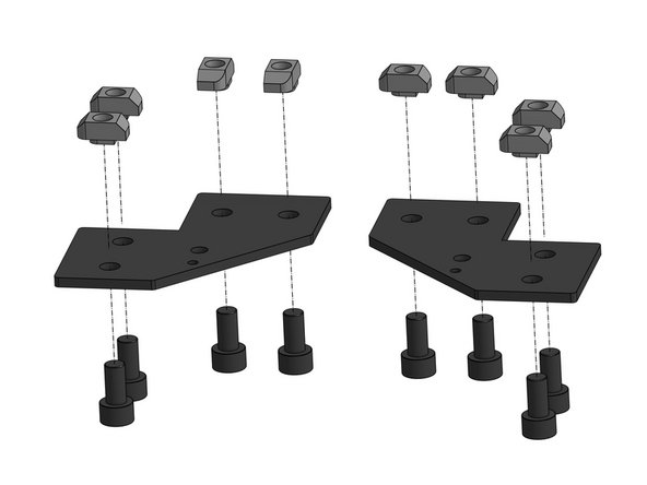
Thread the Cap Head Screws M6x12 through the idler plates. Four screws per plate
-
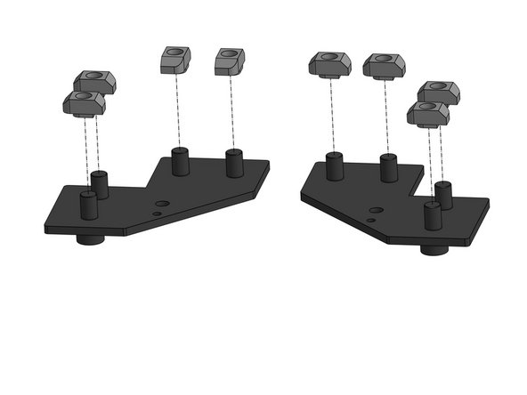
Attach the 3030 M6 T-nut to the screws. Don't tighten yet
-
-
-
Looking from the back of the printer we will now focus on:
-
The right XY idler
-
The left XY idler
-
-
-
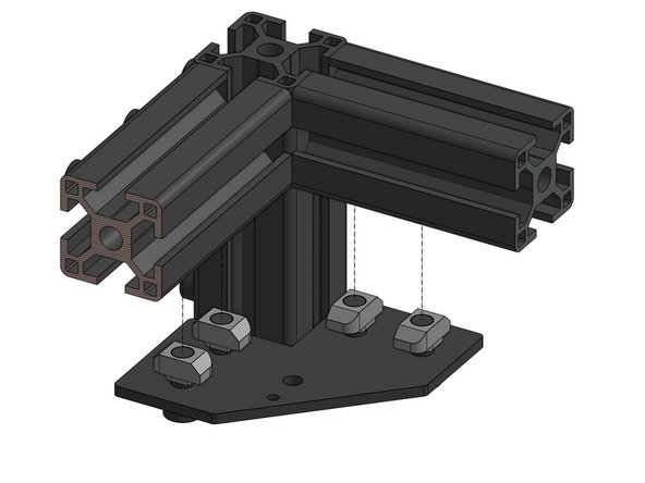
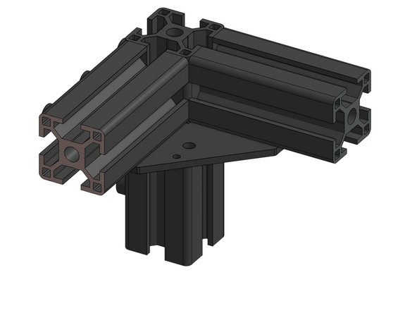
Attach the right XY Idler base to the frame. Fasten the nuts firmly
-
Repeat for the left side
-
-
-
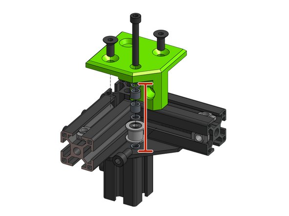
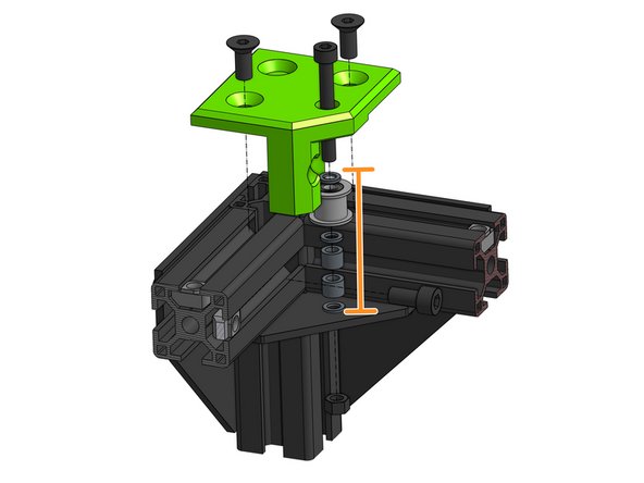
Thread the bearing stack on the DN912 M5x40mm screw that goes through the xy_idler_right part
-
The order for the bearing stack from the bottom is: shim, idler, shim, 2x 6mm spacer, shim
-
Slide the 3030 M6 T-nuts into their place in the extusion
-
-
-
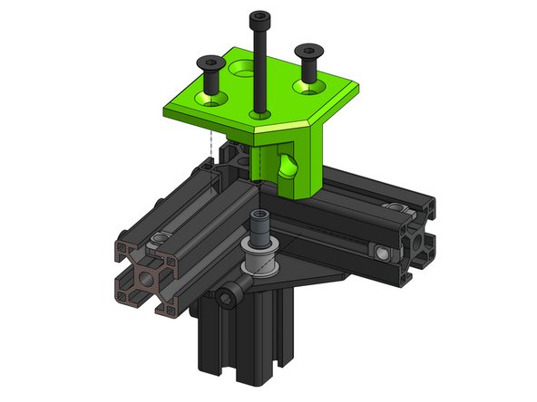
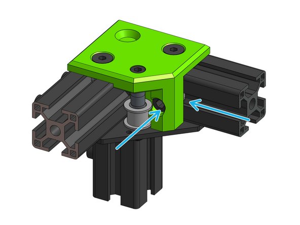
Close the assembly by attaching the xy_idler_right part to the frame. Bolt it to the frame with the DIN7991 M6 14mm screws
-
The M5 screw holding the bearing stack should thread through the metal plate
-
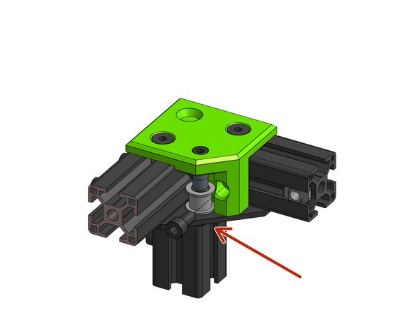
Attach the M5 nut from the bottom, do not over tighten - it should be snug but should not prevent the idler from spinning
-
Attach the side DIN912 M6 12mm screw and nut to secure the assembly
-
-
-
Repeat the same steps for the left XY Idler assembly.
-
The only difference (aside from it being mirrored) is that the bearing stack is upside down - from the bottom it's: shim, 2x 6mm spacers, shim, idler, shim
-
-
-
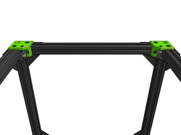
This is how the XY Idler assemblies should look like looking from the back
-