Steps
11
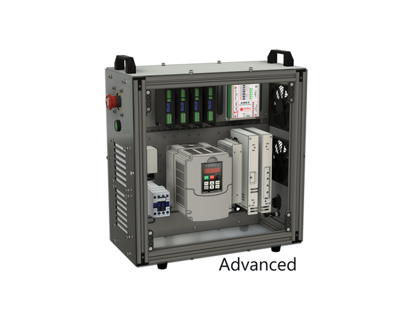
- 04. Advanced Bundle 11 steps

In Progress
This guide is currently being written. Reload periodically to see the latest changes.

User-Contributed Guide
This guide is not managed by the site's staff.

Private
This guide will not appear in search results and can only be viewed by team members!
Quiz
0
Introduction
BEFORE STARTING:
Before beginning this guide, you must prepare all the necessary wires for the assembly. Below is a list of the required wires. The following nomenclature will be used: (Wire Length)_(AWG)_(Wire Color)_(A-End Connector)_(B-End Connector)_(ID number).
Use a small piece of tape to label each wire to ensure a smooth assembly process.
- WIRING LIST
-
-
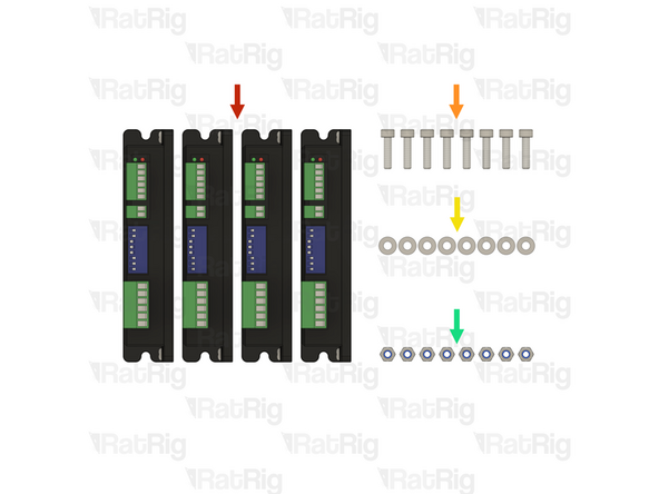
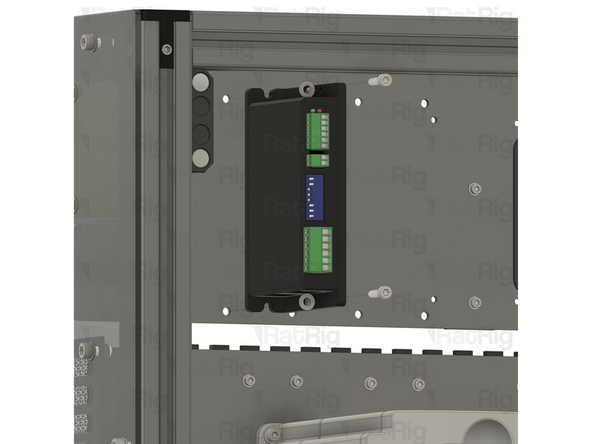
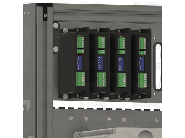
4x Stepper driver - OMC DM542T
-
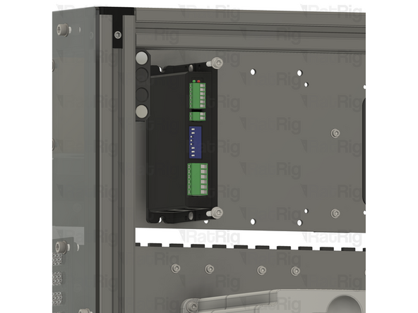
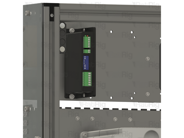
8x M4x16 cap head screw
-
8x M4 washer
-
8x M4 locking hex nut
-
-
-
Insert wisdom here
-
-
-
Insert wisdom here
-
-
-
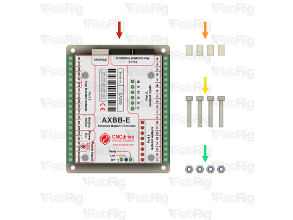
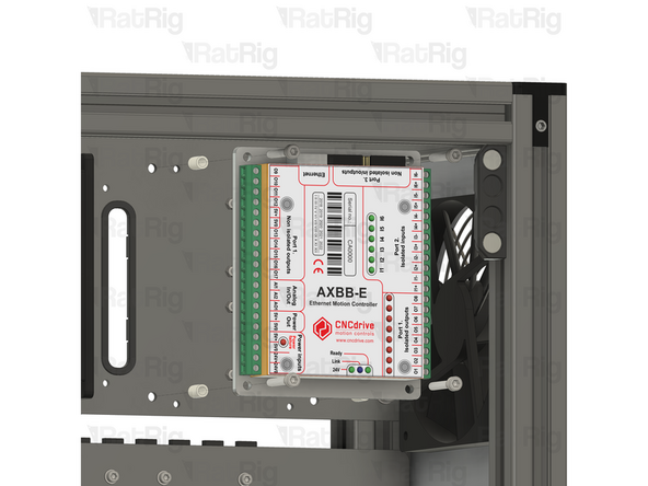
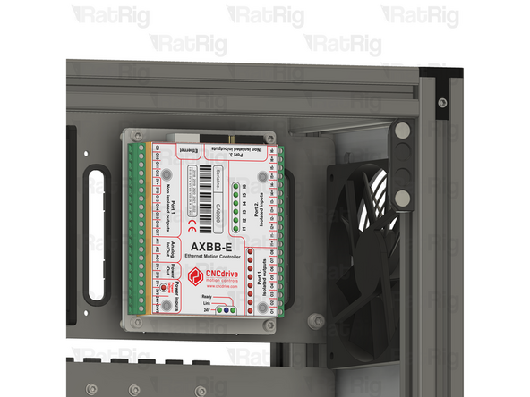
1x CNCDrive AXBB-E CNC controller
-
4x Spacer - Nylon - 4.2x6.3x10mm
-
4x M4x25 cap head screw
-
4x M4 locking hex nut
-
-
-
1x CNCDrive AXBB-E CNC controller
-
4x Spacer - Nylon - 4.2x6.3x10mm
-
4x M4x25 cap head screw
-
-
-
4x M4x25 cap head screw
-
4x M5 locking hex nut
-
-
-
5x M3x6 cap head screw
-
5x M3 washer
-
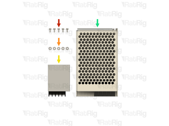
1x Meanwell RS-15-5 5V PSU
-
1x Meanwell RSP-75-24 24V PSU
-
-
-
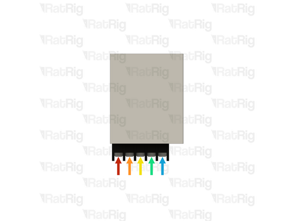
It is recommended to wire the power supply before installing it in the electronics enclosure. Please connect the following wires:
-
XXmm - 18AWG BROWN (A-Fork, B-Ferrule) (XX)
-
XXmm - 18AWG BLUE (A-Fork, B-Ferrule) (XX)
-
XXmm - 18AWG YELLOW/GREEN (A-Fork, B-Ferrule) (XX)
-
XXmm - 16AWG BLACK (A-Fork, B-Ferrule) (XX)
-
XXmm - 16AWG RED (A-Fork, B-Ferrule) (XX)
-
Connect all the wires above to the power supply, using the fork connectors on each wire
-
After insertion, attempt to pull the wire to verify that it is securely attached
-
-
-
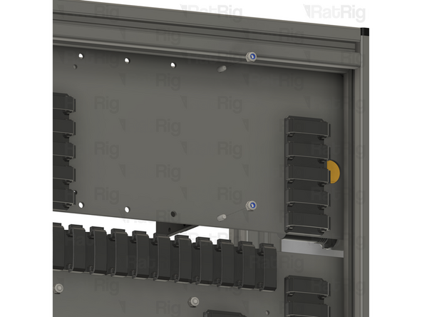
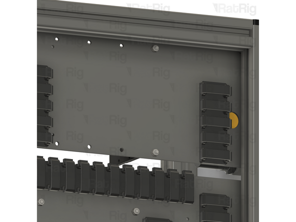
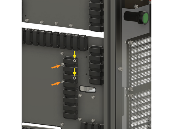
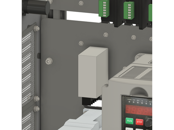
Install the component using the designated holes
-
2x M3x6 cap head screw
-
2x M3 washer
-
-
-
Insert wisdom here
-
-
-
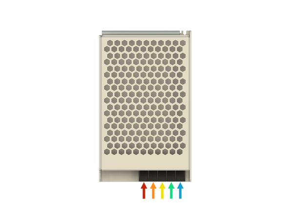
It is recommended to wire the power supply before installing it in the electronics enclosure. Please connect the following wires:
-
XXmm - 16AWG RED (A-Fork, B-Ferrule) (XX)
-
XXmm - 16AWG BLACK (A-Fork, B-Ferrule) (XX)
-
XXmm - 18AWG YELLOW/GREEN (A-Fork, B-Ferrule) (XX)
-
XXmm - 18AWG BLUE (A-Fork, B-Ferrule) (XX)
-
XXmm - 18AWG BROWN (A-Fork, B-Ferrule) (XX)
-
Connect all the wires above to the power supply, using the fork connectors on each wire
-
After insertion, attempt to pull the wire to verify that it is securely attached
-