
-
-
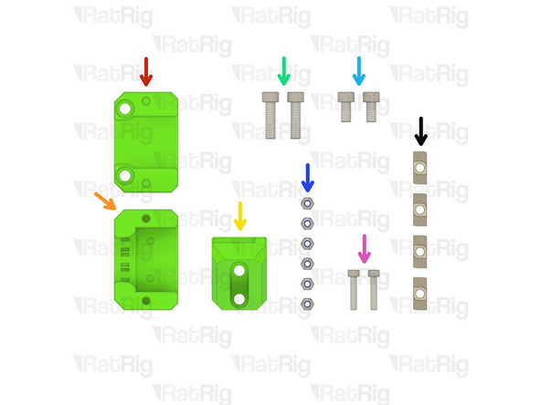
2x M6x16 Cap Head Screw
-
2x 4040 Drop-in T-Nut - M6
-
6x M3 Nylon Locking Hex Nut
-
3x SN04-N2 Proximity Sensor
-
2x sh_pro_y_endstop_mount Printed Part
-
1x sh_pro_x_endstop_spacer Printed Part
-
4x M3x35 Cap Head Screw
-
2x M3x25 Cap Head Screw
-
-
-
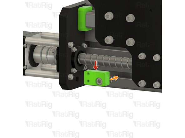
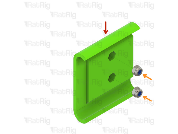
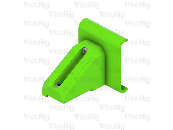
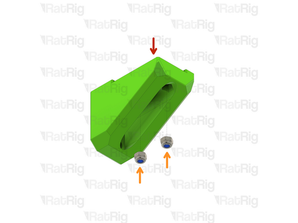
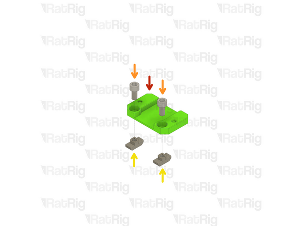
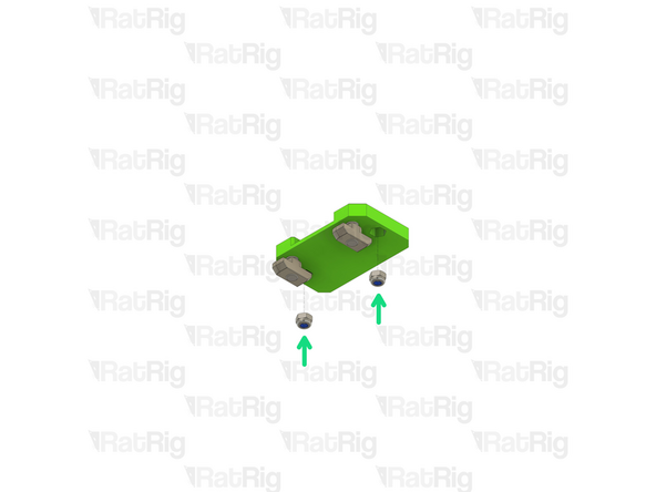
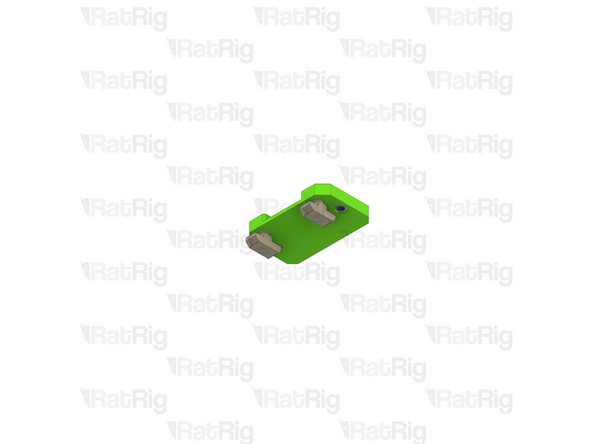
sh_pro_y_endstop_mount Printed Part
-
M3 Nylon Locking Hex Nut
-
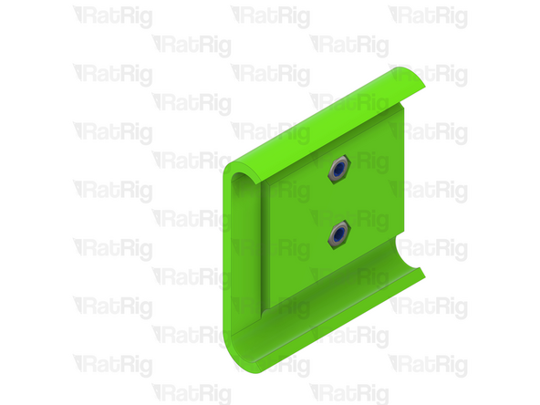
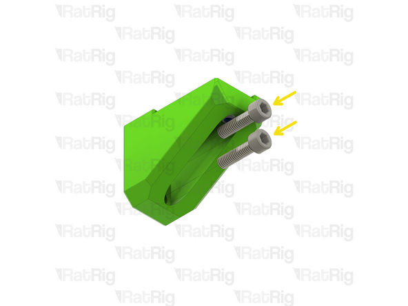
Insert an M3 nut into each of the two hex holes on the printed part
-
Make sure that the M3 nuts are fully inserted into the printed part, otherwise installation of the endstop will be impossible
-
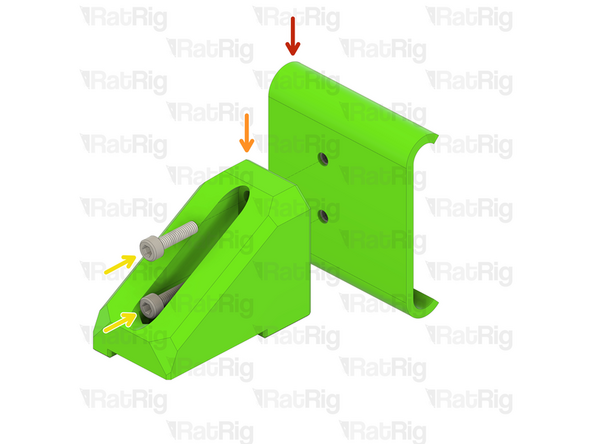
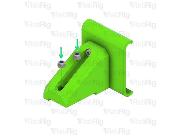
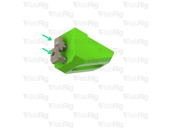
M6x16 Cap Head Screw
-
4040 Drop-in T-Nut - M6
-
Loosely thread the 4040 T-Nut on to the M6x16 screw. Do not tighten it at this point.
-
-
-
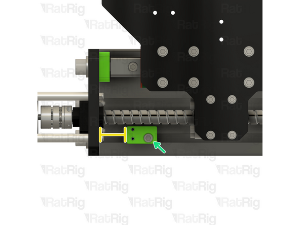
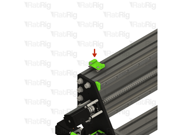
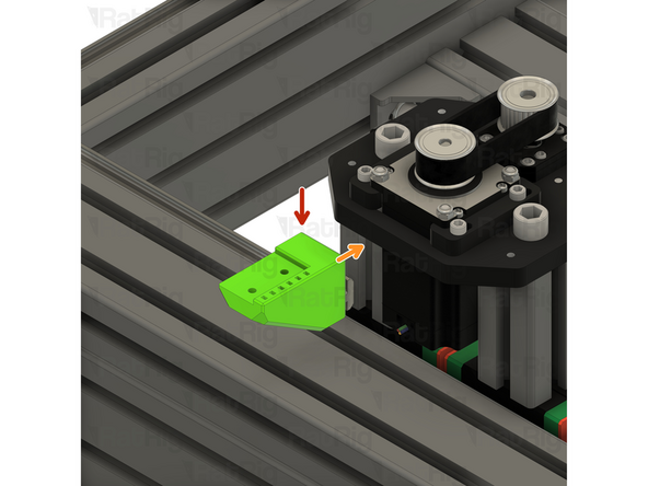
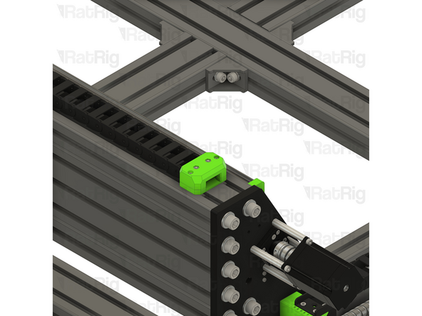
Y-axis Endstop Mount from the Previous Step
-
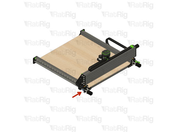
Position the endstop mount in to the bottom slot of the 40120 extrusion
-
The marked distance should measure roughly 31mm
-
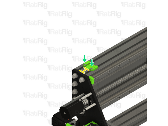
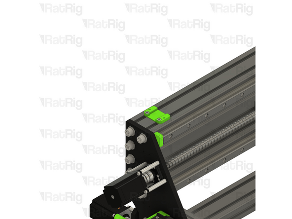
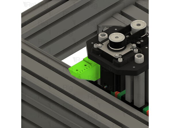
Tighten the M6x16 screw to secure the endstop mount to the StrongHold PRO frame
-
Take care not to over tighten the M6x16 screw as you can damage the printed part
-
-
-
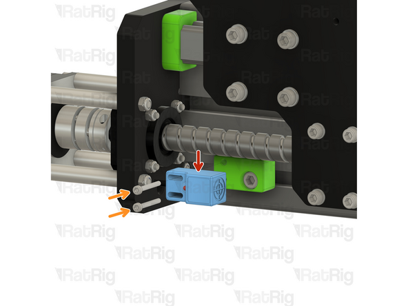
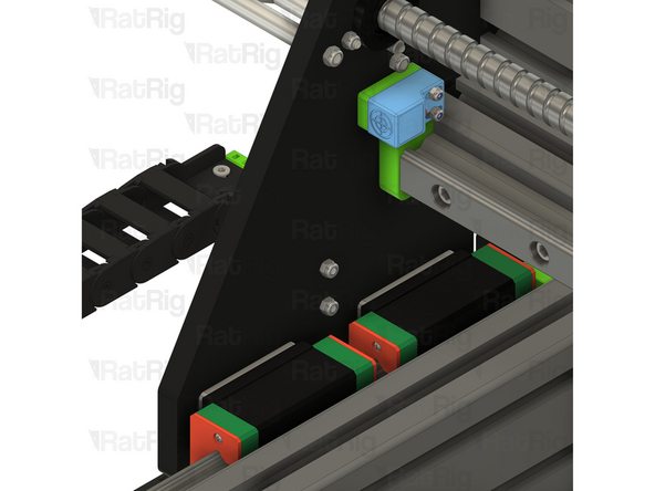
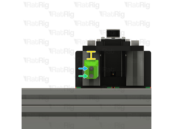
SN04-N2 Proximity Sensor
-
M3x25 Cap Head Screw
-
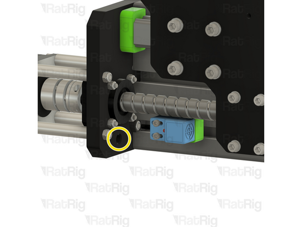
Secure the Y-axis endstop to the mount with the M3x25 screws
-
Pass the end of the proximity sensor cable through the marked hole
-
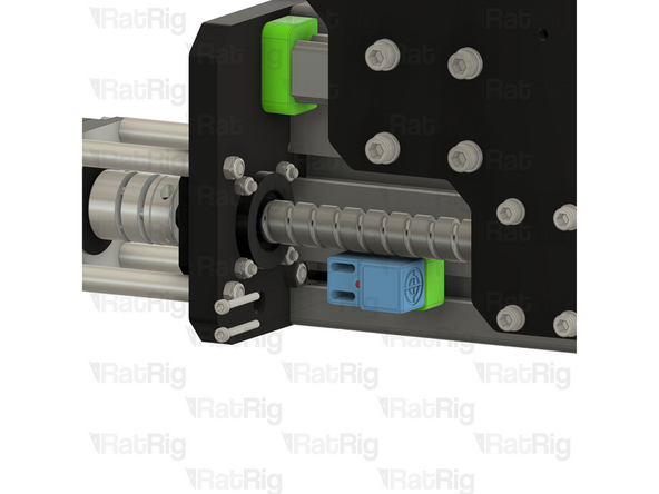
Repeat Steps 2, 3 and 4 to install the second Y-axis endstop.
-
-
-
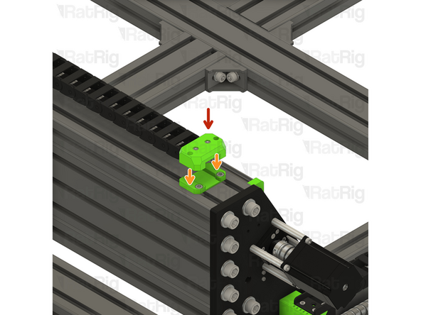
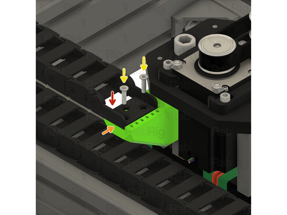
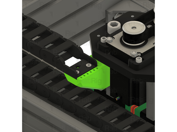
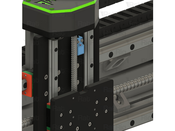
M3x35 Cap Head Screw
-
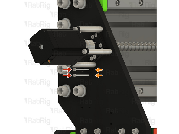
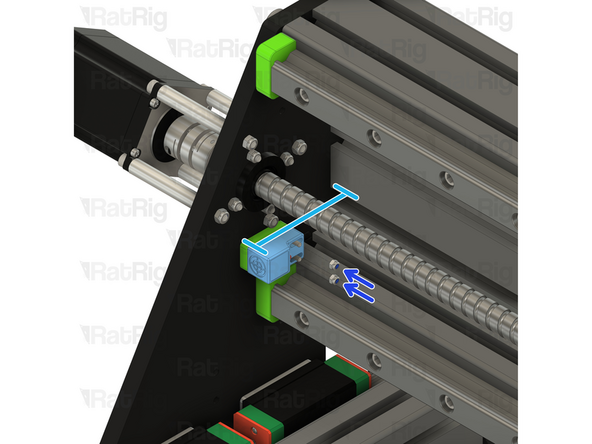
Insert the M3x35 screws through the marked holes in the X-axis gantry plate
-
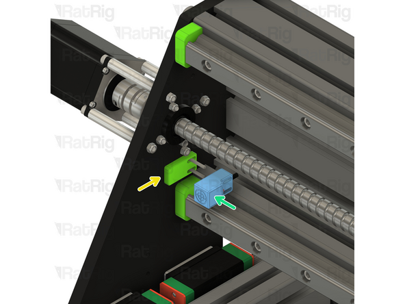
sh_pro_x_endstop_spacer Printed Part
-
SN04-N2 Proximity Sensor
-
Position the endstop and spacer so that the measurement from the rear extrusion to the front of the sensor is between 76 and 78mm
-
M3 Nylon Locking Hex Nut
-
-
-
2x M4x16 Cap Head Screw
-
2x M4x25 Cap Head Screw
-
4x M4 Nylon Locking Hex Nut
-
4x M4x16 Countersunk Screw
-
1x 1500mm 30x15 Drag Chain (2000mm for StrongHold Pro 1000x1500 or 1500x1500)
-
1x sh_pro_frame_y_dragchain_mount Printed Part
-
1x sh_pro_frame_y_dragchain_arm Printed Part
-
1x sh_pro_gantry_y_dragchain_mount Printed Part
-
-
-
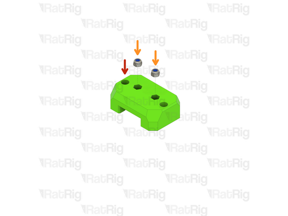
sh_pro_gantry_y_dragchain_mount Printed Part
-
M4 Nylon Locking Hex Nut
-
Insert the M4 Nylon Locking Hex Nuts into the hex holes on the printed part
-
Set this assembly aside until Step 13
-
-
-
sh_pro_frame_y_dragchain_mount Printed Part
-
M4 Nylon Locking Hex Nut
-
Insert the M4 Nylon Locking Hex Nuts into the hex holes on the printed part
-
-
-
Assembly from the previous step
-
sh_pro_frame_y_dragchain_arm Printed Part
-
M4x16 Cap Head Screw
-
Insert an M4x16 screw through each hole in the back of the printed arm and into the hex nuts fitted to the existing assembly
-
Tighten the M4x16 screws to secure the printed parts together
-
M4 Nylon Locking Hex Nut
-
Insert the M4 Nylon Locking Hex Nuts into the hex holes on the printed part
-
-
-
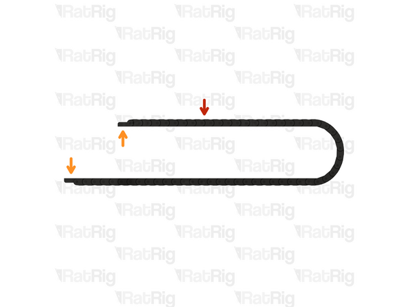
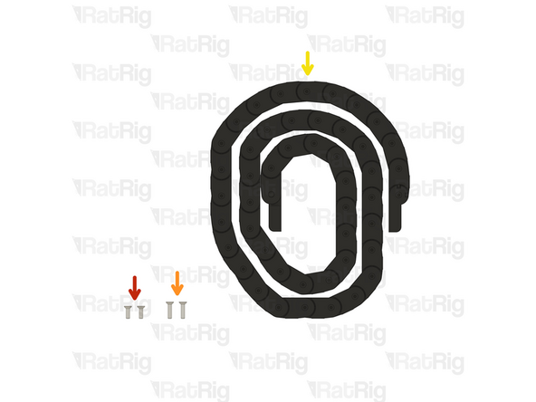
1500mm 30x15 Drag Chain
-
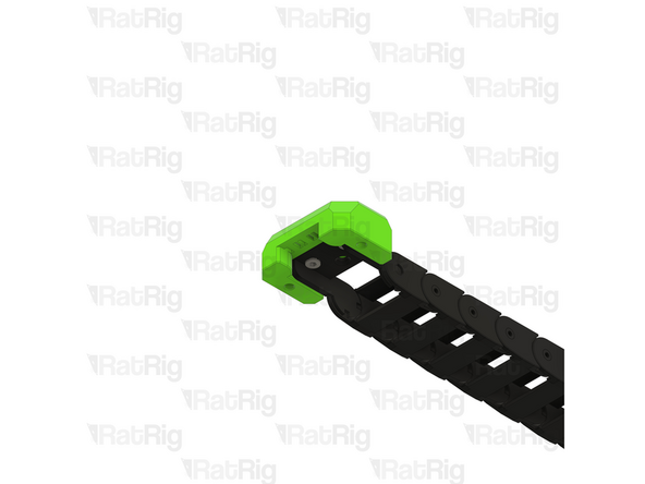
Please note that the shape of the drag chain ends may differ from those shown in the guide imagery. This is normal
-
2000mm for StrongHold Pro 1000x1500 or 1500x1500
-
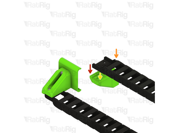
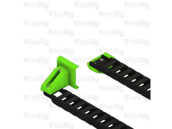
The ends of the drag chain need to be oriented correctly
-
If your drag ends are oriented as shown in the first image, skip to the next step
-
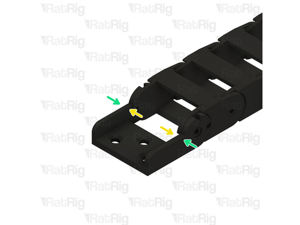
Remove the drag chain end by either compressing or expanding the link in the chain, as shown
-
Once removed, flip the orientation of the end and re-install it.
-
It may be easier to remove the drag chain end by opening the drag chain link next to the end. The drag chain is designed to be opened to allow easier installation and maintenance.
-
-
-
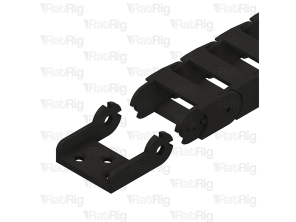
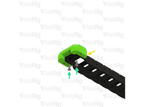
Assembly from Step 9
-
Drag chain assembly - Male End
-
Align the drag chain end with the printed part as shown. Only one of the drag chain ends will fit correctly.
-
M4x16 Countersunk Screw
-
Insert an M4x16 screw into each hole in the drag chain and tighten them, securing the drag chain to the mount
-
-
-
Assembly from Step 8
-
Drag chain assembly - Female End
-
Align the drag chain end with the printed part as shown
-
M4x16 Countersunk Screw
-
Insert an M4x16 screw into each hole in the drag chain and tighten them, securing the drag chain to the mount
-
-
-
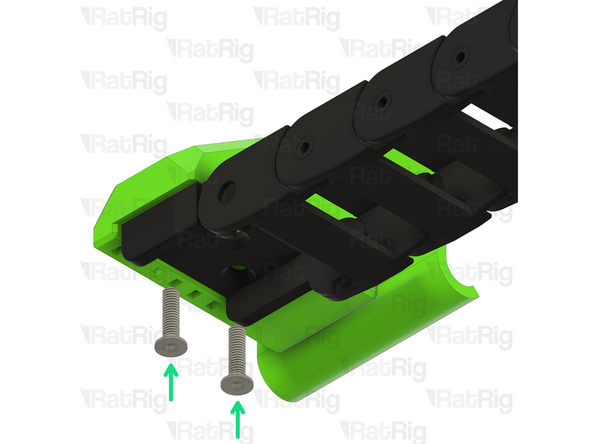
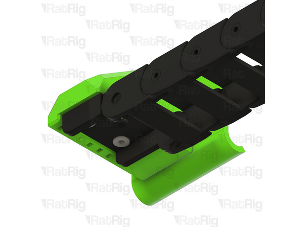
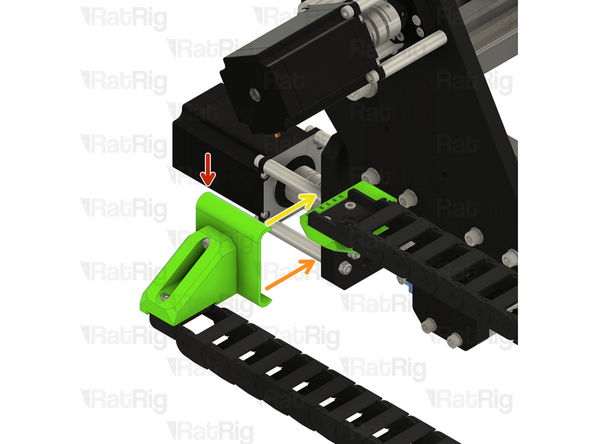
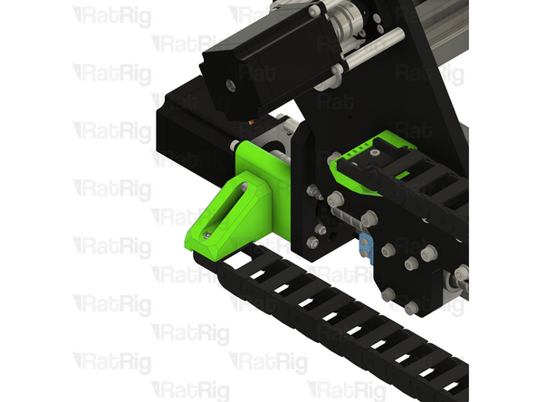
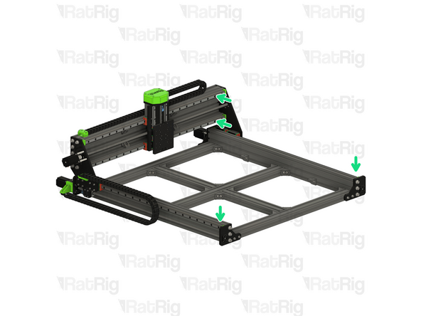
Drag Chain Assembly - Frame End
-
Hook the bottom of the printed part on to the lower aluminium spacers
-
Push the top of the printed part slowly but strongly and it will clip onto the upper aluminium spacers, securing the mount to the frame
-
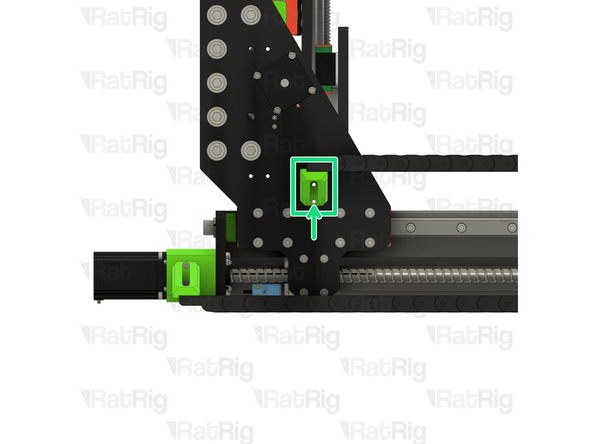
Align the holes in the printed mount on the other end of the drag chain with the holes in the gantry plate as shown
-
-
-
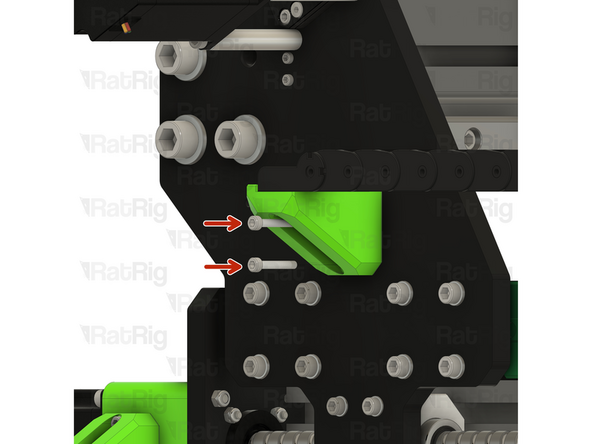
M4x25 Cap Head Screw
-
Insert an M4x25 screw through each hole in the back of the printed arm and through the gantry plate
-
M4 Nylon Locking Hex Nut
-
Secure the end of the drag chain mount to the gantry by installing an M4 hex nut onto each screw and tightening
-
-
-
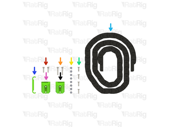
1x sh_pro_x_dragchain_mount_base Printed Part
-
1x sh_pro_x_dragchain_mount_cap Printed Part
-
1x sh_pro_toolhead_x_dragchain_mount Printed Part
-
2x M6x22 Cap Head Screw
-
2x M6x12 Cap Head Screw
-
6x M4 Nylon Locking Hex Nut
-
2x M4x20 Cap Head Screw
-
4x 4040 Drop-in T-Nut - M6
-
-
-
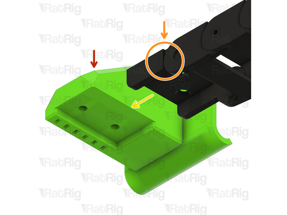
sh_pro_toolhead_x_dragchain_mount Printed Part
-
M4 Nylon Locking Hex Nut
-
Insert the M4 Nylon Locking Hex Nuts into the hex holes on the printed part
-
M6x22 Cap Head Screw
-
4040 Drop-in T-Nut - M6
-
The two T-nuts must be offset as shown, to allow installation
-
Set this assembly aside until Step 23
-
-
-
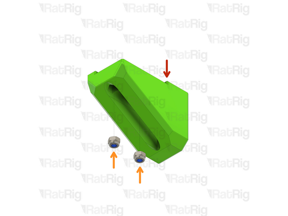
sh_pro_x_dragchain_mount_base Printed Part
-
M6x12 Cap Head Screw
-
4040 Drop-in T-Nut - M6
-
Loosely thread the 4040 T-Nuts on to the M6x12 screws. Do not tighten them at this point.
-
M4 Nylon Locking Hex Nut
-
Insert an M4 nut into each of the two hex holes on the printed part
-
Set this assembly aside until Step 22
-
-
-
2x M4x12 Countersunk Screw
-
2x M4x16 Countersunk Screw
-
1x 1500mm 30x15 Drag Chain
-
2000mm for StrongHold Pro 1000x1500 or 1500x1500
-
-
-
1500mm 30x15 Drag Chain
-
Please note that the shape of the drag chain ends may differ from those shown in the guide imagery. This is normal
-
2000mm for StrongHold Pro 1000x1500 or 1500x1500
-
The ends of the drag chain need to be oriented correctly
-
If your drag ends are oriented as shown in the first image, skip to the next step
-
Remove the drag chain end by either compressing or expanding the link in the chain, as shown
-
Once removed, flip the orientation of the end and re-install it.
-
It may be easier to remove the drag chain end by opening the drag chain link next to the end. The drag chain is designed to be opened to allow easier installation and maintenance.
-
-
-
sh_pro_x_dragchain_mount_cap Printed Part
-
M4 Nylon Locking Hex Nut
-
Drag chain assembly - Male End
-
Align the drag chain end with the printed part as shown. Only one of the drag chain ends will fit correctly.
-
M4x12 Countersunk Screw
-
Insert an M4x12 screw into each hole in the drag chain and tighten them, securing the drag chain to the mount
-
-
-
X-axis drag chain mount base assembly from Step 18
-
Position the assembly on to the top of the X-axis gantry extrusion, making sure the T-nuts drop into the slot
-
Check the marked distance, it should measure roughly 30-35mm
-
Tighten the marked M6x12 screws to secure the mount to the X-axis gantry
-
-
-
X-axis drag chain arm assembly from Step 17
-
Insert the X-axis drag chain arm into the marked 4040 extrusion
-
Position the assembly as shown. The indicated measurement should be 20mm
-
Fasten the lower M6x22 screw fully
-
Fasten the upper M6x22 screw fully
-
-
-
X-axis drag chain assembly from Step 20
-
Place the X-axis drag chain assembly on to the previously installed base
-
M4x20 Cap Head Screw
-
Insert an M4x20 screw through the cap and fasten into the hex nuts in the base
-
-
-
Drag chain assembly - Female End
-
Align the drag chain end with the printed part as shown
-
M4x16 Countersunk Screw
-
Insert an M4x16 screw into each hole in the drag chain and tighten them, securing the drag chain to the mount
-
-
-
4x M5x20 Cap Head Screw
-
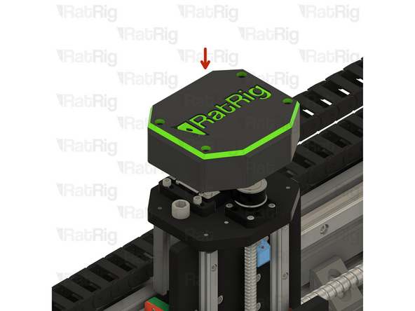
1x sh_pro_z_transmission_cover Printed Part
-
-
-
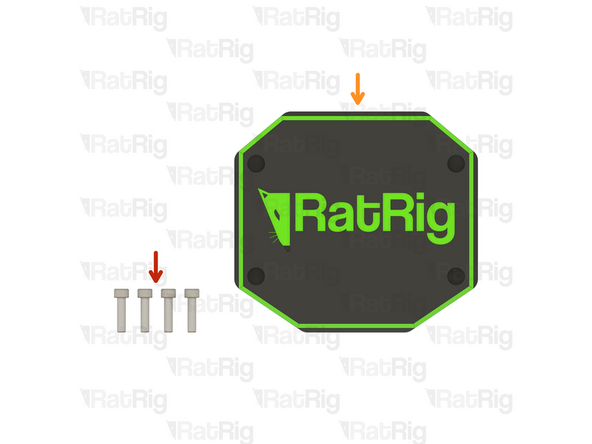
sh_pro_z_transmission_cover Printed Part
-
Place the Z transmission on top of the Z-axis, aligning the edges
-
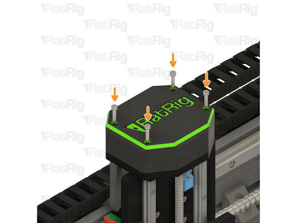
M5x20 Cap Head Screw
-
Insert each M5x20 screw into the printed part as shown
-
Fully tighten each M5x20 screw to secure the cover in place
-
-
-
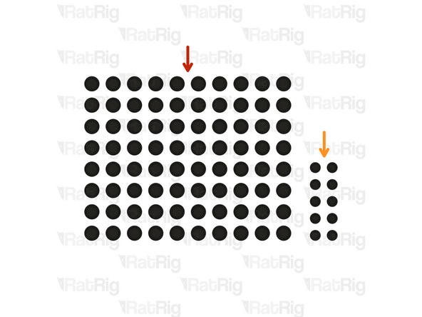
80x HG25 Screw Cover
-
96x for StrongHold PRO 1000x1500
-
112x for StrongHold PRO 1500x1500
-
10x HG15 Screw Cover
-
-
-
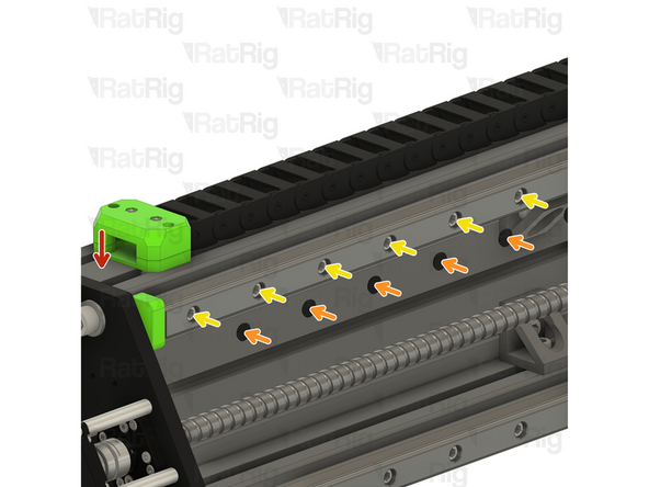
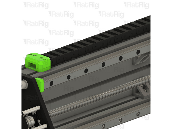
StrongHold PRO X-Axis Gantry
-
HG25 Screw Cover
-
Insert an HG25 screw cover into each screw hole of the HG25 linear rail
-
Install an HG25 screw cover into every screw hole on the marked linear rails
-
-
-
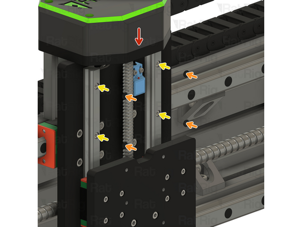
StrongHold PRO Z-Axis
-
HG15 Screw Cover
-
Insert an HG15 screw cover into each screw hole of the HG15 linear rail
-


Cancel: I did not complete this guide.
One other person completed this guide.