-
-
X Base 2040 Profiles (x2)
-
Y C-Beam Profiles (x2). Slide them inside the X-Gantry carriages.
-
-
-
Thread the 2 Y Lead Screws through the Nut Blocks on the X-Gantry carriages.
-
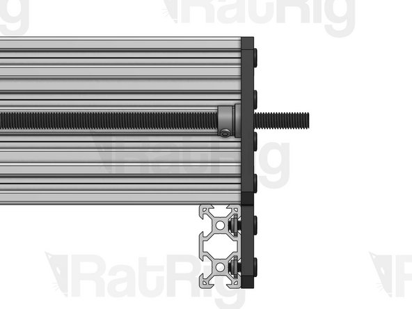
Once you're done, you should see about 3cm of lead screw coming out of each end of each C-Beam.
-
Y Lead Screws (x2)
-
-
-
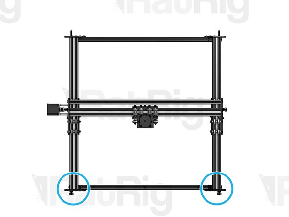
Repeat this step for each of the 4 Y End Plates, installing one on each corner of your base. Do not fully tighten before making sure your frame is perfectly square - squareness is really important! Best way to check squareness is to measure the diagonals of the rectangle formed by the 4 profiles. They should have the exact same length.
-
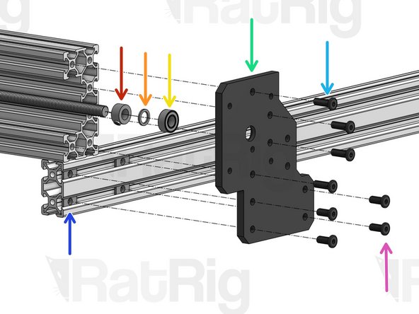
Lock Collar 8mm. Set it in position, but don't tighten for now.
-
Precision Shim 12x8x1mm
-
688ZZ Ball Bearing
-
Y End Plate
-
Low Profile Screw M5x15mm (for C-Beam profiles)
-
Low Profile Screw M5x12mm (for 2040 profiles)
-
T-Nut M5
-
-
-
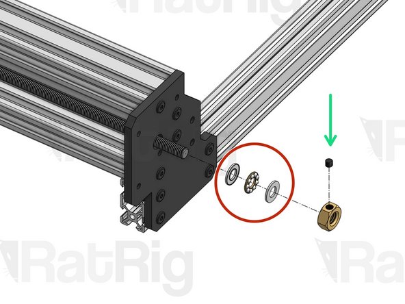
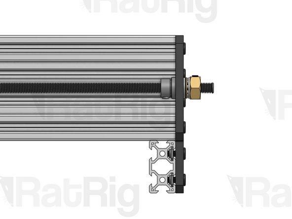
Thrust Bearing
-
Tensioner Nut. For now, screw it in just a tiny bit, so it holds its position.
-
Repeat this step for the front Y End Plates on both sides. Play close attention to the image to understand exactly where they are (position is not reversible)
-
-
-
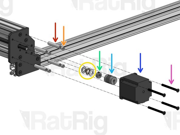
Aluminium Spacer 40mm
-
Aluminium Spacer 6mm
-
Thrust Bearing
-
Lock Collar 8mm. Set in position, don't tighten yet.
-
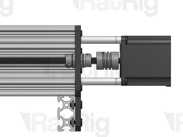
Flexible Coupling - 1/4" x 8mm. Set in position, don't tighten yet.
-
Nema 23 Motor
-
Low Profile Screw M5x55mm
-
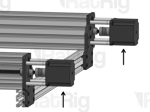
Repeat this step for both Y Motors. Then, tension your lead screws, just like you did on the X Axis.
-