
Steps
29
- 07. Bed Arm Assemblies 29 steps

User-Contributed Guide
This guide is not managed by the site's staff.
Quiz
0
Introduction
Please note: The lead screw measurements provided in this guide are based upon building a 300x300 V-Core 3.
If you are building a machine of a different size, please refer to the following list for the correct lead screw length for your machine:
- 200x200: 3x 280mm lead screws
- 300x300: 3x 380mm lead screws
- 400x400: 3x 480mm lead screws
- 500x500: 3x 580mm lead screws
-
-
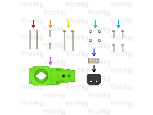
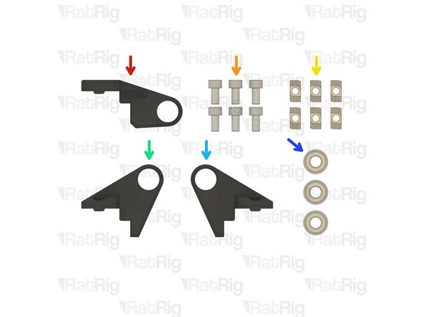
1x bed_arm_right_3.1 Printed Part
-
1x bed_arm_left_3.1 Printed Part
-
4x M3x12 Countersink Screw
-
4x 3x35mm Dowel Pin
-
2x Neodymium Magnet
-
4x M3 Nylon Locking Hex Nut
-
-
-
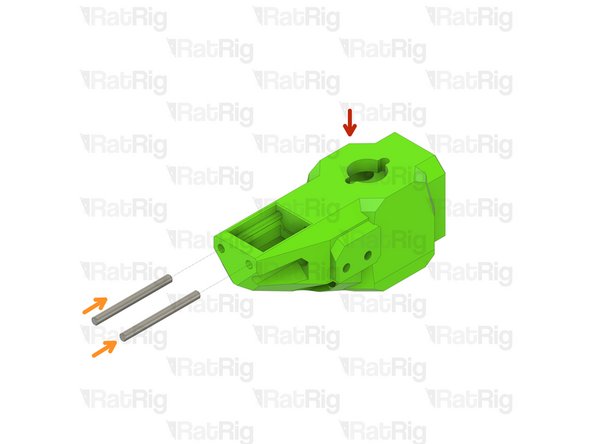
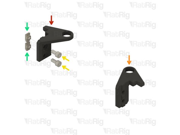
bed_arm_left_3.1 Printed Part
-
bed_arm_right_3.1 Printed Part
-
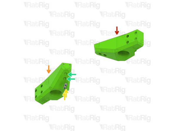
3x35mm Dowel Pin
-
Insert two dowel pins into each arm as shown
-
Please note: The dowel pins are quite a tight fit. It is recommended to use a pair of pliers to install them by twisting each pin in the same manner you would install a screw
-
Do not use excessive force to install the pins as this can cause damage to the printed part
-
-
-
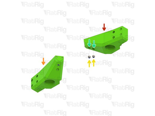
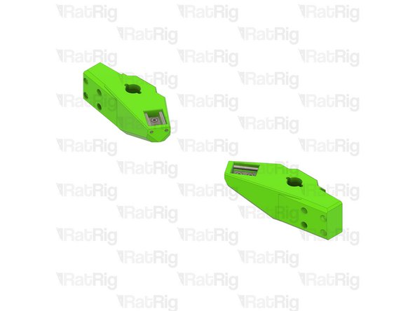
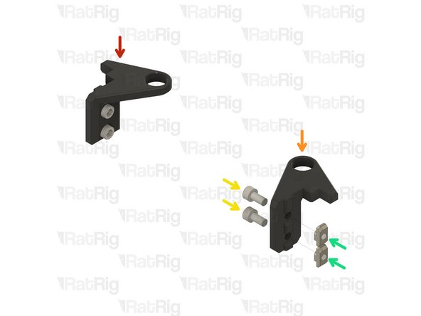
Left Bed Arm Assembly
-
Right Bed Arm Assembly
-
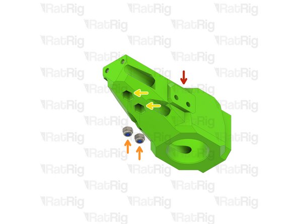
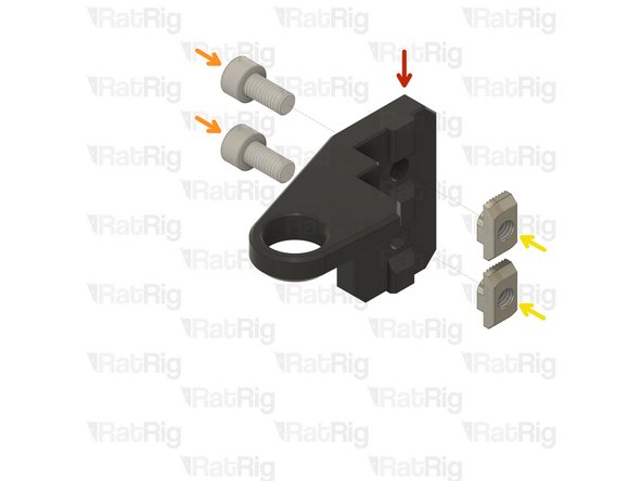
M3 Nylon Locking Hex Nut
-
Insert an M3 nut into each marked position
-
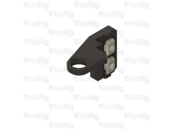
-
-
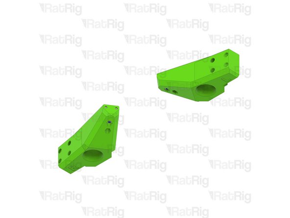
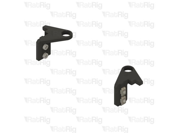
Left Bed Arm Assembly
-
Right Bed Arm Assembly
-
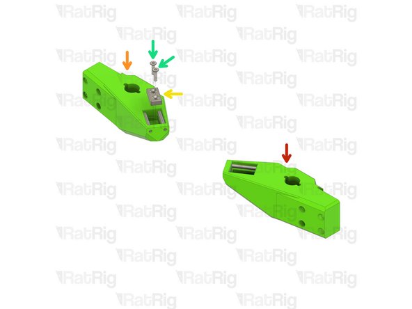
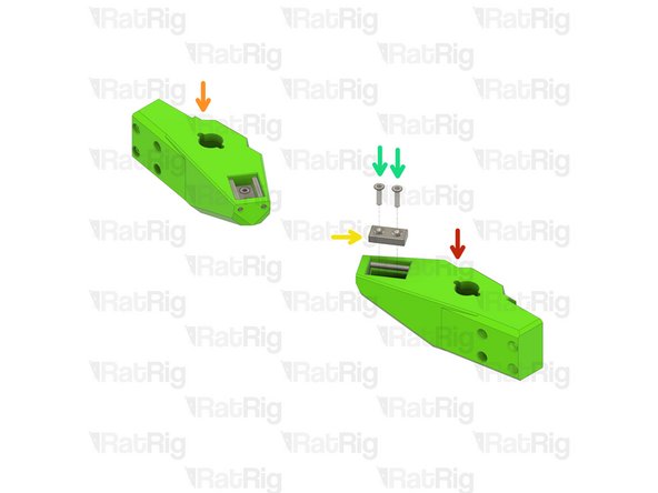
Neodymium Magnet
-
M3x12 Countersink Screw
-
Install two M3x12 countersink screws into each magnet and then install them into the arms as shown
-
Take care not to over tighten the M3x12 screws as you can crack the magnets and/or damage the printed parts
-
Set these assemblies aside until Step 7
-
-
-
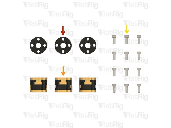
3x TR8x4 POM Lead screw Nut
-
3x Rat Rig Bi-Material Lead Screw Decoupler
-
12x M3x8 Cap Head Screw
-
-
-
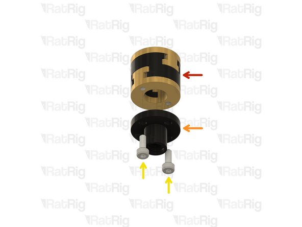
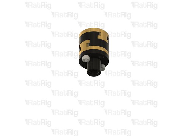
Rat Rig Bi-Material Lead Screw Decoupler
-
TR8x4 POM Lead screw Nut
-
M3x8 Cap Head Screw
-
Assemble all three lead screw decouplers as shown. Set one aside until Step 13, keep the other two for the next step
-
-
-
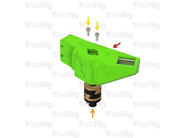
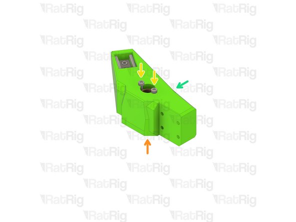
Left bed arm assembly
-
Lead screw decoupler assembly
-
M3x8 Cap Head Screw
-
Install a lead screw decoupler assembly into each arm as shown
-
Take care not to over tighten the M3x8 screws as you damage the printed parts
-
Right bed arm assembly
-
-
-
2x 3x35mm Dowel Pin
-
2x M3x12 Countersink Screw
-
2x M3x35 Cap Head Screw
-
4x M3 Nylon Locking Hex Nut
-
4x M3x12 Cap Head Screw
-
1x Neodymium Magnet
-
1x bed_arm_rear_3.1 Printed Part
-
1x bed_cable_relief_3.1 Printed Part
-
-
-
bed_arm_rear_3.1 Printed Part
-
3x35mm Dowel Pin
-
Insert two dowel pins into the arm as shown
-
Please note: The dowel pins are quite a tight fit. It is recommended to use a pair of pliers to install them by twisting each pin in the same manner you would install a screw
-
Do not use excessive force to install the pins as this can cause damage to the printed part
-
-
-
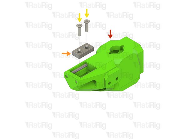
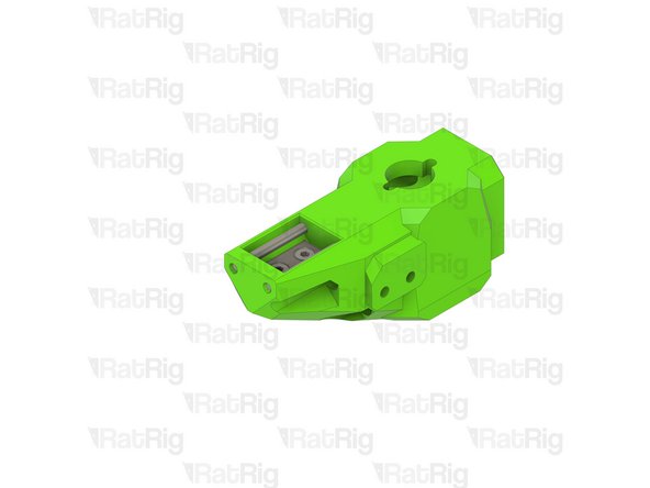
Rear bed arm assembly
-
M3 Nylon Locking Hex Nut
-
Insert an M3 nut into each marked position
-
-
-
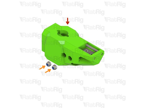
Rear bed arm assembly
-
Neodymium Magnet
-
M3x12 Countersink Screw
-
Install two M3x12 countersink screws into the magnet and then install it into the arm as shown
-
Take care not to over tighten the M3x12 screws as you can crack the magnet and/or damage the printed part
-
-
-
Rear bed arm assembly
-
M3 Nylon Locking Hex Nut
-
bed_cable_relief_3.1 Printed Part
-
M3x35 Cap Head Screw
-
Install the M3x35 screws through the bed_cable_relief_3.1 printed part, rear bed arm, and fasten them into the M3 nylon locking nuts
-
Take care not to over tighten the M3x35 screws as you can damage the printed parts
-
-
-
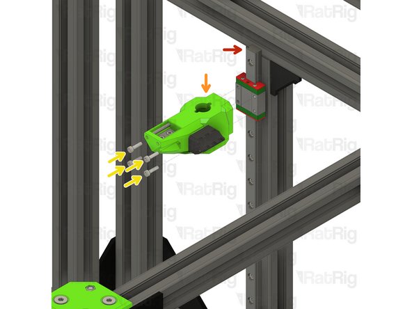
V-Core 3.1 Frame Assembly
-
Rear bed arm assembly
-
M3x12 Cap Head Screw
-
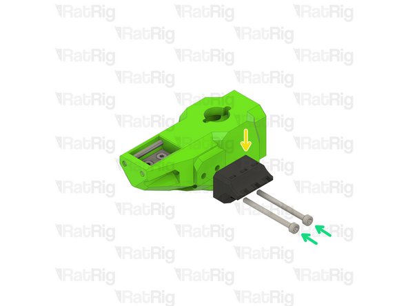
Install the M3x12 screws into the arm as shown, then fasten the arm to the rear linear rail carriage
-
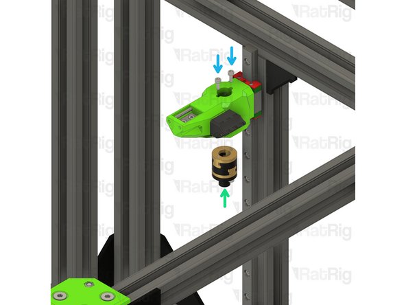
Lead screw decoupler assembly from Step 6
-
M3x8 Cap Head Screw
-
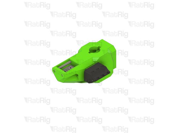
Install a lead screw decoupler assembly into the rear arm as shown
-
Take care not to over tighten the M3 screws as you damage the printed part
-
-
-
Rear bed arm assembly
-
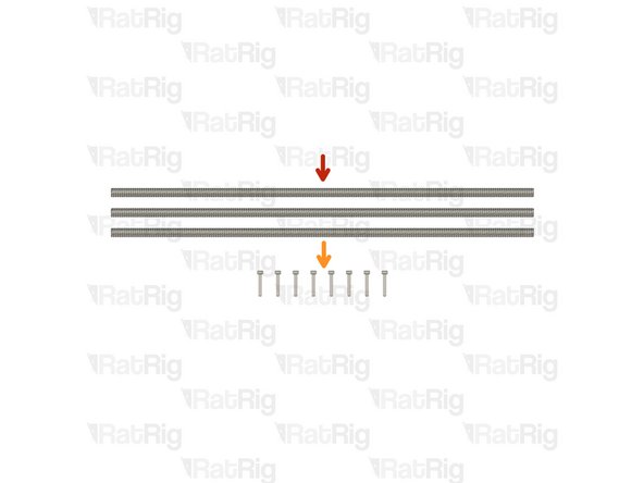
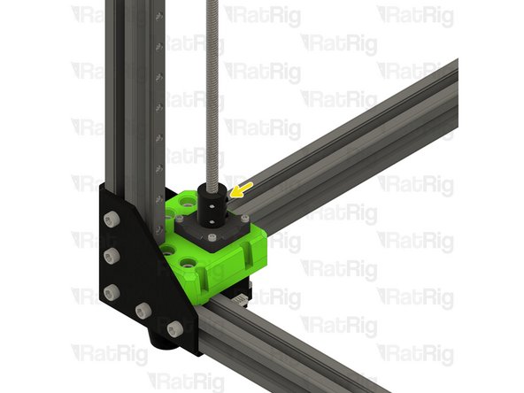
380mm TR8x4 Lead Screw
-
Install the lead screw through the rear bed arm and decoupler
-
Do not force the lead screw through the POM nut on the decoupler as this can cause damage. It should thread through smoothly
-
Rigid Lead Screw Coupler
-
Continue threading the lead screw through the arm until it reaches the rigid lead screw coupler on the rear Z-axis motor mount
-
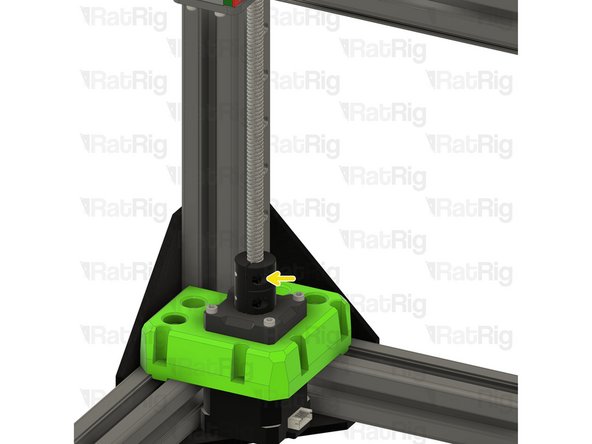
Insert the lead screw fully into the rigid coupler
-
Fasten the marked M3 screw to secure the lead screw to the NEMA17 motor
-
-
-
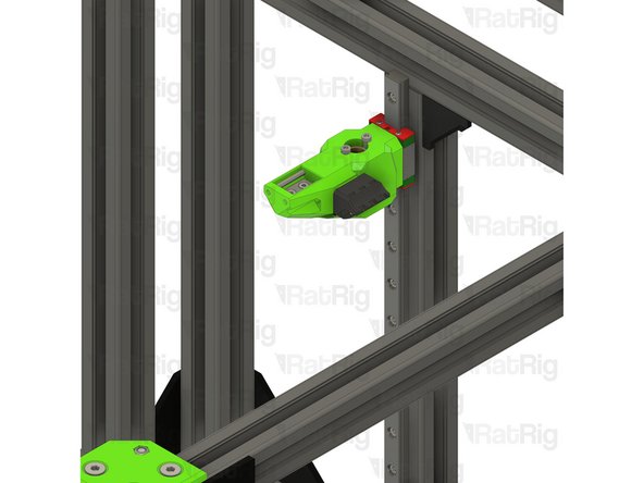
Front right bed arm assembly
-
380mm TR8x4 lead screw
-
Install the lead screw through the front bed arm and decoupler
-
Do not force the lead screw through the POM nut on the decoupler as this can cause damage. It should thread through smoothly
-
Continue threading the lead screw through the arm until it reaches the rigid lead screw coupler on the front right Z-axis motor mount
-
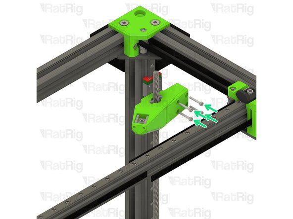
M3x20 Cap Head Screw
-
Install each screw through the bed arm assembly as shown, then fasten the arm to the linear rail carriage
-
-
-
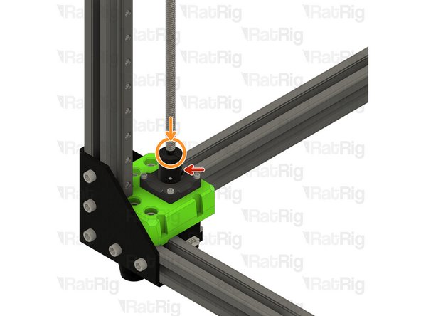
Rigid Lead Screw Coupler
-
Insert the lead screw fully into the rigid coupler
-
Fasten the marked M3 screw to secure the lead screw to the NEMA17 motor
-
-
-
Front left bed arm assembly
-
380mm TR8x4 lead screw
-
Install the lead screw through the front bed arm and decoupler
-
Do not force the lead screw through the POM nut on the decoupler as this can cause damage. It should thread through smoothly
-
Continue threading the lead screw through the arm until it reaches the rigid lead screw coupler on the front left Z-axis motor mount
-
M3x20 Cap Head Screw
-
Install each screw through the bed arm assembly as shown, then fasten the arm to the linear rail carriage
-
-
-
Rigid Lead Screw Coupler
-
Insert the lead screw fully into the rigid coupler
-
Fasten the marked M3 screw to secure the lead screw to the NEMA17 motor
-
-
-
1x lead_screw_constraint_rear_3.1 Printed Part
-
6x M6x12 Cap Head Screw
-
6x 3030 Drop-in T-Nut - M6
-
1x lead_screw_constraint_front_left_3.1 Printed Part
-
1x lead_screw_constraint_front_right_3.1 Printed Part
-
3x F688ZZ Ball Bearing
-
-
-
lead_screw_constraint_rear_3.1 Printed Part
-
M6x12 Cap Head Screw
-
Insert an M6x12 cap head screw into each position on the lead screw constraint as shown
-
3030 Drop-in T-Nut - M6
-
Loosely thread a 3030 T-Nut onto each of the M6x20 screws. Do not tighten them at this point
-
-
-
lead_screw_constraint_left_3.1 Printed Part
-
lead_screw_constraint_right_3.1 Printed Part
-
M6x12 Cap Head Screw
-
Insert an M6x12 cap head screw into each position on the lead screw constraint as shown
-
3030 Drop-in T-Nut - M6
-
Loosely thread a 3030 T-Nut onto each of the M6x20 screws. Do not tighten them at this point
-
-
-
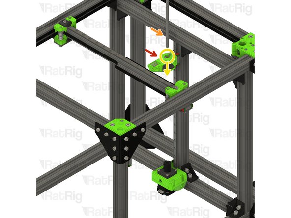
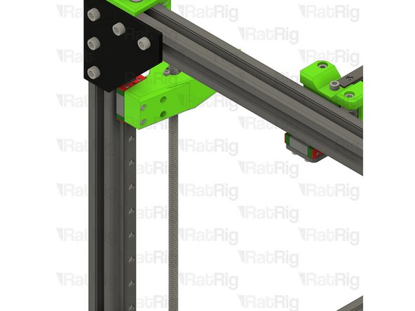
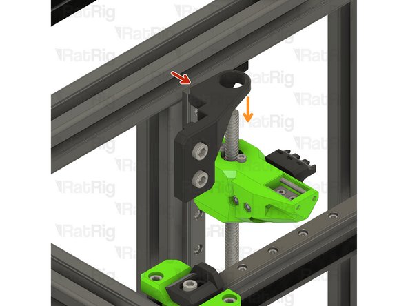
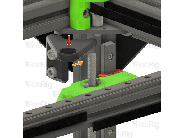
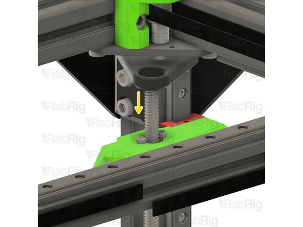
Rear lead screw constraint assembly from Step 21
-
Position the constraint assembly so that the rear lead screw passes through the hole
-
Rotate the constraint assembly clockwise and fit it to the rear 3030 extrusion as shown
-
Push the constraint assembly upwards until it touches the horizontal 3030 extrusion
-
-
-
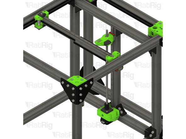
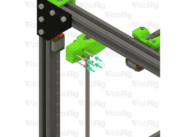
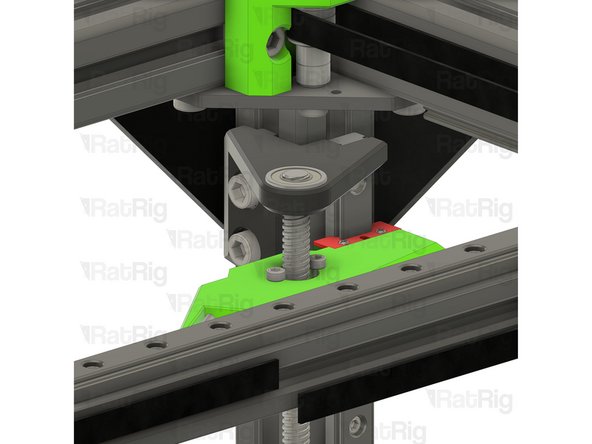
M6x12 Cap Head Screw
-
Fasten both M6x12 screws to secure the constraint assembly to the V-Core 3.1 frame
-
Take care not to over tighten the M6 screws as you damage the printed part
-
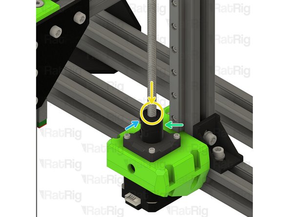
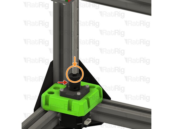
F688ZZ Ball Bearing
-
Fit the bearing onto the lead screw and into the constraint assembly as shown
-
-
-
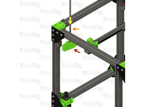
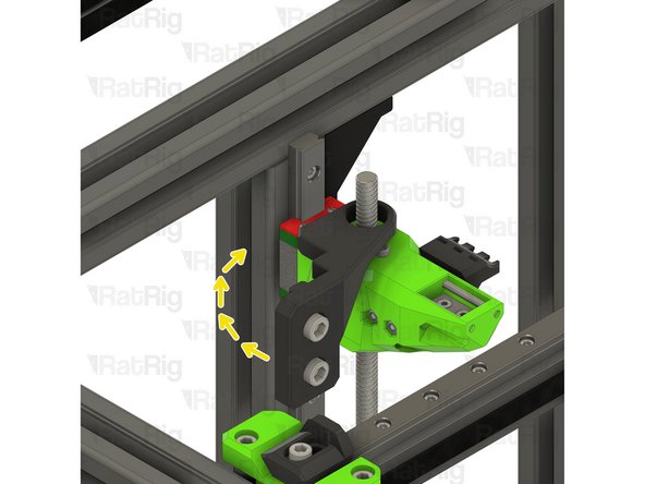
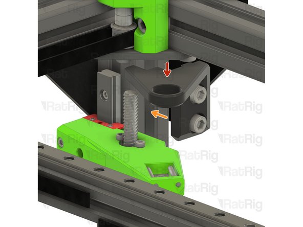
Right lead screw constraint assembly from Step 22
-
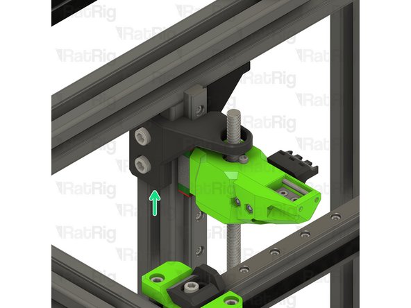
Fit the constraint assembly to the frame as shown
-
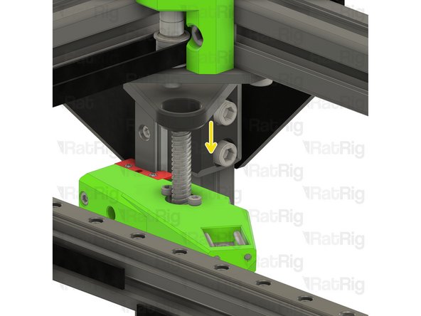
Push the constraint assembly downwards until its top is flush with the top of the linear rail
-
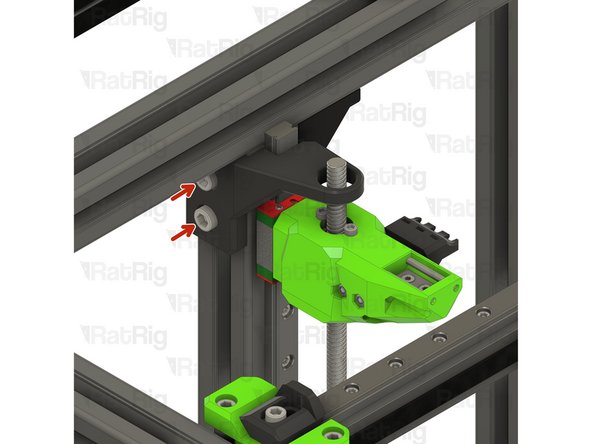
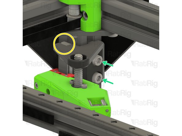
Fasten both M6x12 screws to secure the constraint assembly to the V-Core 3.1 frame
-
-
-
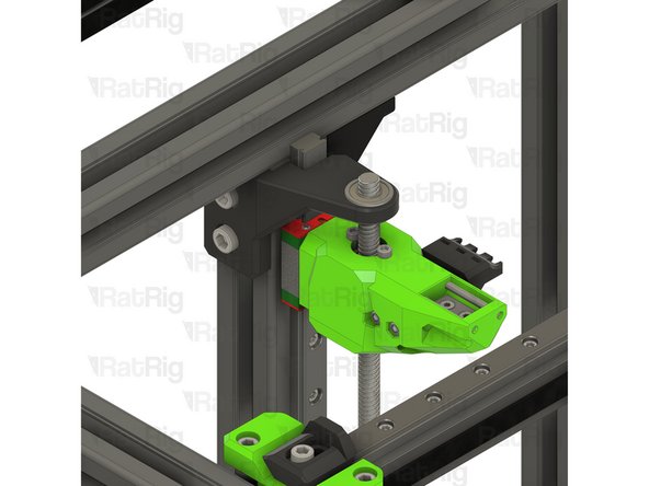
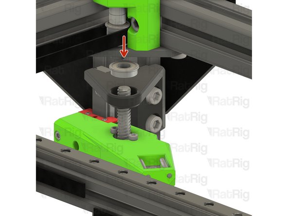
F688ZZ Ball Bearing
-
Fit the bearing onto the lead screw and into the constraint assembly as shown
-
-
-
Left lead screw constraint assembly from Step 22
-
Fit the constraint assembly to the frame as shown
-
Push the constraint assembly downwards until its top is flush with the top of the linear rail
-
Fasten both M6x12 screws to secure the constraint assembly to the V-Core 3.1 frame
-
-
-
F688ZZ Ball Bearing
-
Fit the bearing onto the lead screw and into the constraint assembly as shown
-


Cancel: I did not complete this guide.
30 other people completed this guide.