Steps
10
- 08. Bed & Y-Axis Endstop Assemblies 10 steps

User-Contributed Guide
This guide is not managed by the site's staff.
Quiz
0
Introduction
Please note: The bed measurements provided in this guide are based upon building a 300x300 V-Core 3.
If you are building a machine of a different size, please refer to the following list for the correct bed measurement for your machine:
- 200x200: 229x229x5mm
- 300x300: 329x329x6mm
- 400x400: 429x429x6mm
- 500x500: 529x529x6mm
-
-
1x 329x329x6mm Machined Bed Plate
-
3x Aluminium Spacer - 6mm
-
3x Threaded Steel Ball
-
3x M5x16 Countersink Screw
-
-
-
To prevent scratches, the bed plate is shipped with a protective film on both sides.
-
Gently peel off the protective film.
-
Repeat for the other side.
-
-
-
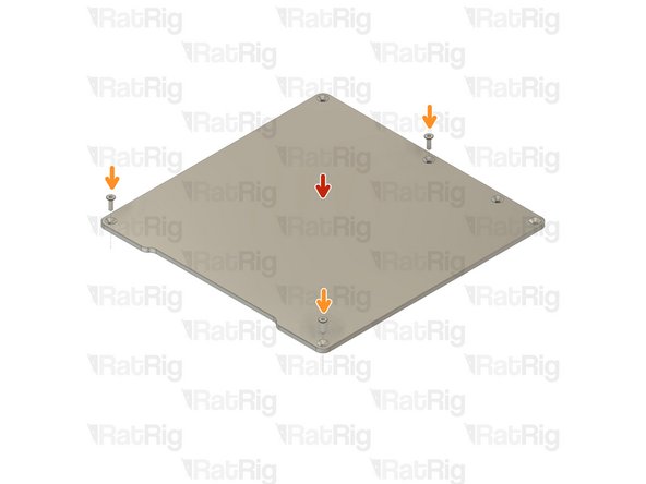
329x329x6mm Machined Bed Plate
-
M5x16 Countersink Screw
-
Insert an M5x16 countersink screw into each of the positions shown on the bed
-
Aluminium Spacer - 6mm
-
Threaded Steel Ball
-
Add an aluminium spacer and threaded steel ball to each of the M5x16 screws
-
Set the bed assembly aside until Step 9
-
-
-
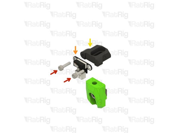
1x y_max_endstop_slider_3.1 Printed Part
-
1x y_max_endstop_block_3.1 Printed Part
-
2x M3x12 Cap Head Screw
-
1x Endstop Module
-
1x M5 Nylon Locking Hex Nut
-
1x 3030 Drop-in T-Nut - M5
-
1x M5x12 Cap Head Screw
-
1x M5x10 Cap Head Screw
-
-
-
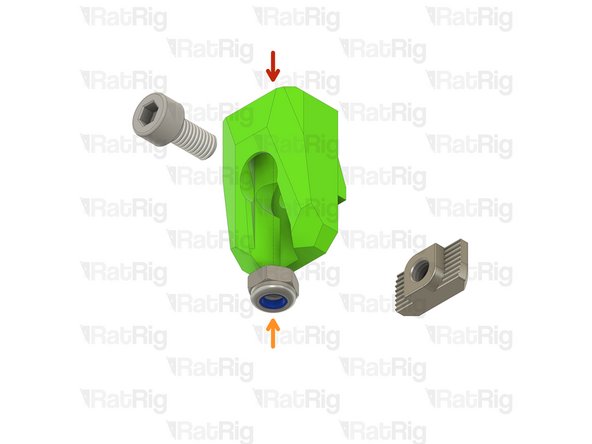
y_max_endstop_block_3.1 Printed Part
-
M5 Nylon Locking Hex Nut
-
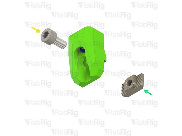
M5x10 Cap Head Screw
-
3030 Drop-in T-Nut - M5
-
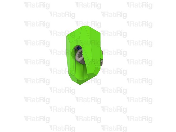
Loosely thread the 3030 T-Nut onto the M5x10 screw. Do not tighten it at this point.
-
-
-
M3x12 Cap Head Screw
-
Endstop Module
-
y_max_endstop_slider_3.1 Printed Part
-
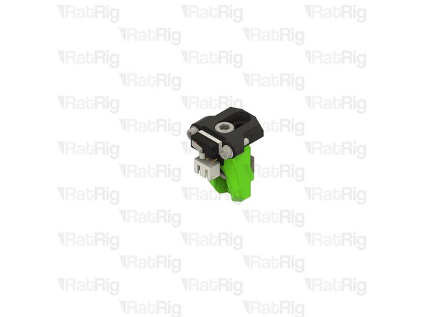
Install an M3x12 screw through each hole on the endstop module and screw it into the printed part
-
M5x12 Cap Head Screw
-
Install the M5x12 screw through the y_max_endstop_slider printed part and fasten it into the M5 nylon hex nut
-
-
-
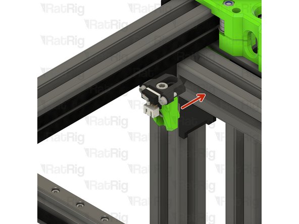
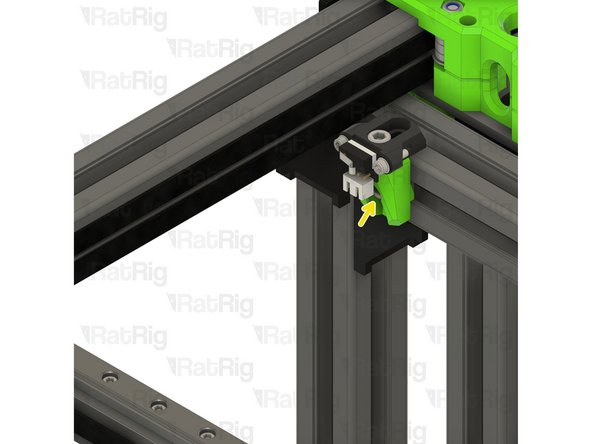
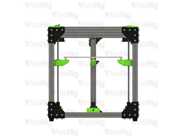
Position the y-axis endstop on to the V-Core 3.1 frame as shown
-
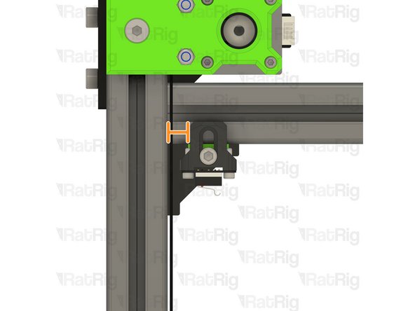
Check that the distance shown measures 11mm
-
Fasten the M5x10 screw to secure the y-axis endstop assembly to the frame
-
-
-
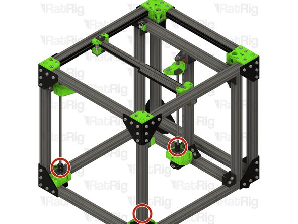
Rotate each z-axis lead screw counter-clockwise to lower the bed arms
-
Stop when the arms are roughly half way down
-
-
-
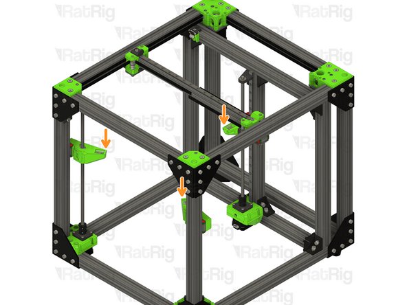
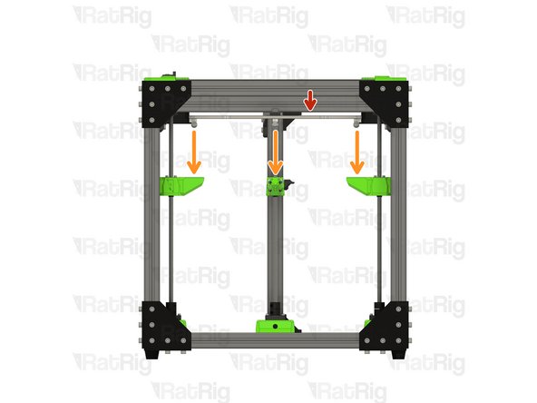
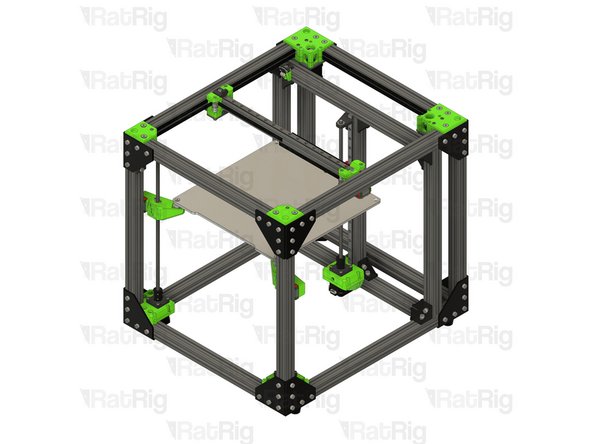
Bed assembly from Step 2
-
Install the bed onto the z-axis arms. Each ball on the bed should rest on the dowel pins in each arm
-
-
-
Continue with the next guide: 09. EVA 3.0 Assembly
-