
Steps
23
- 08. Electronics Enclosure 23 steps

User-Contributed Guide
This guide is not managed by the site's staff.
Quiz
0
Video Overview
-
-
case_front printed part
-
case_back printed part
-
14x M3 Nylon Locking Hex Nut
-
-
-
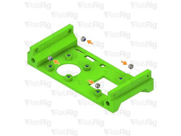
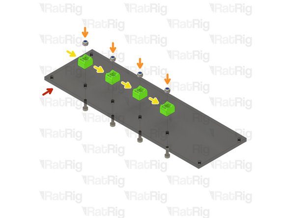
4x M3 Nylon Locking Hex Nut
-
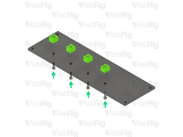
Insert an M3 nylon locking nut into each of the four positions shown
-
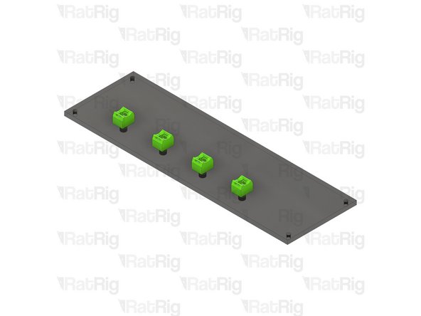
Set this assembly aside until Step 16
-
-
-
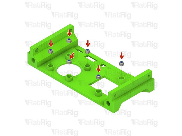
6x M3 Nylon Locking Hex Nut
-
4x M3 Nylon Locking Hex Nut
-
Insert an M3 nylon locking nut into each of the ten positions shown
-
Set this assembly aside until Step 16
-
-
-
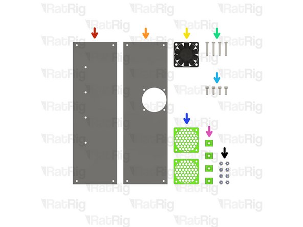
1x Electronics Panel - Base
-
1x Electronics Panel - Top
-
1x 40x10mm 24v Axial Fan
-
4x M3x20 Button Head Screw
-
4x M3x10 Cap Head Screw
-
2x 40mm_fan_cage printed part
-
4x case_wire_holder printed part
-
8x M3 Nylon Locking Hex Nut
-
-
-
Electronics Panel - Base
-
M3 Nylon Locking Hex Nut
-
case_wire_holder printed part
-
Install an M3 nylon locking nut into each case_wire_holder as shown
-
M3x10 Cap Head Screw
-
Fasten the case_wire_holders to the panel using the M3x10 screws
-
Take care not to over tighten the M3x10 screws as you can damage the printed parts
-
Set this assembly aside until Step 19
-
-
-
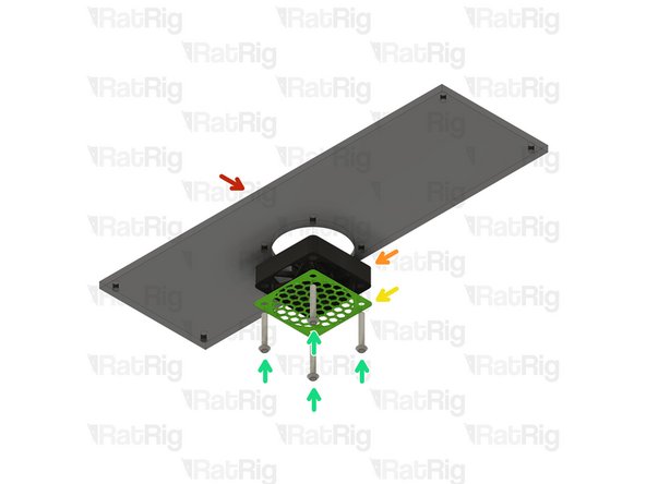
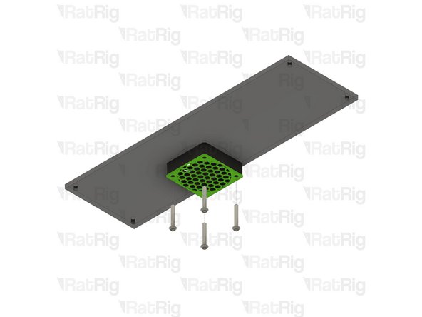
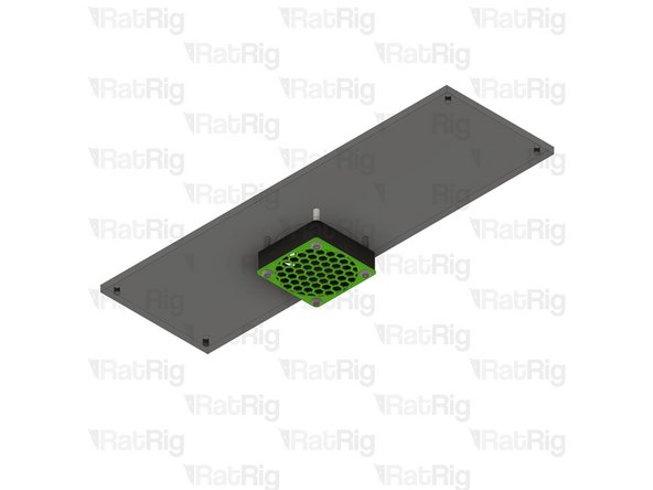
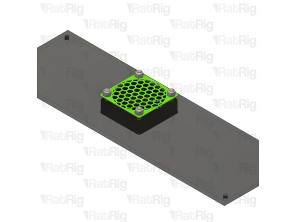
Electronics Panel - Top
-
40x10mm 24v Axial Fan
-
Orient the fan so that the fan label is against the 40mm_fan_cage printed part
-
40mm_fan_cage printed part
-
M3x20 Button Head Screw
-
Insert an M3x20 screw through the printed part, fan, and into the panel. Repeat this for the other 3 screws as shown
-
-
-
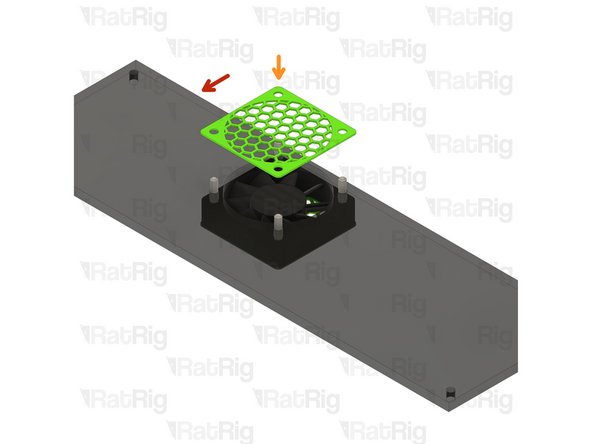
Assembly from the previous step
-
40mm_fan_cage printed part
-
Install the second 40mm_fan_cage onto the other side of the fan as shown
-
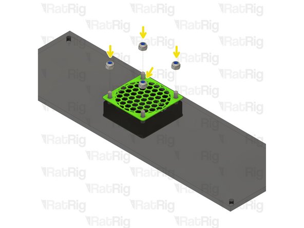
M3 Nylon Locking Hex Nut
-
Fasten an M3 nylon locking nut onto each M3x20 screw to secure the fan and both cages to the panel
-
Take care not to over tighten the M3x20 screws & nuts as you can damage the printed parts or the fan
-
Set this assembly aside until Step 16
-
-
-
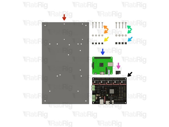
1x Electronics Panel - Board
-
4x M2.5x16 Cap Head Screw & Nut
-
4x M2.5x5 Nylon Standoff
-
4x M3x16 Cap Head Screw & Nut
-
4x M3x6 Nylon Standoff
-
1x Raspberry Pi 3a+
-
1x Micro SD Card (Not Provided)
-
1x BIGTREETECH SKR 2 / Octopus 1.1 motherboard
-
-
-
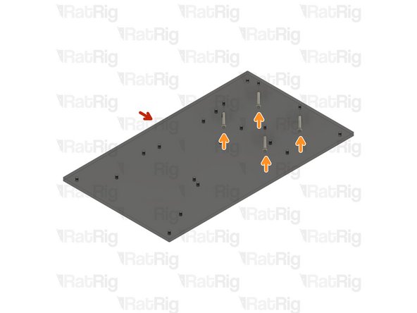
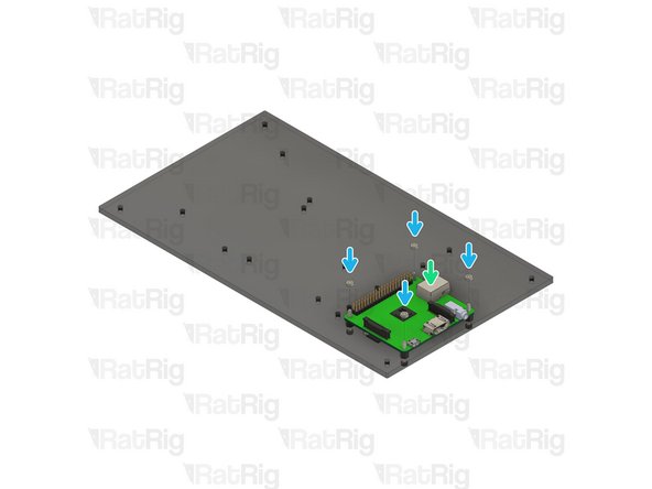
Electronics Panel - Board
-
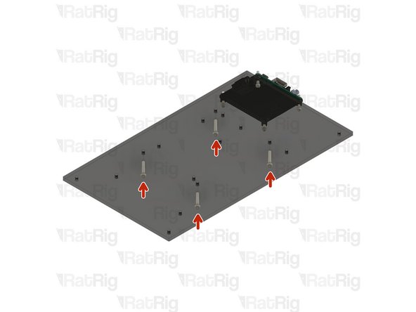
M2.5x16 Cap Head Screw
-
Insert an M2.5x16 screw into each of the holes in the electronics panel as shown
-
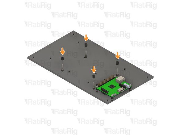
M2.5x5 Nylon Standoff
-
Raspberry Pi 3a+
-
M2.5 Nut
-
Add an M2.5 nylon standoff onto each screw, followed by the Raspberry Pi 3a+. Secure the Raspberry Pi to the panel by installing an M2.5 nut onto each screw
-
Take care not to over tighten the M2.5 screws & nuts as you can damage the Raspberry Pi
-
-
-
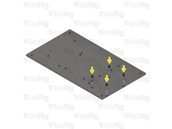
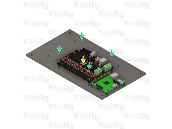
M3x16 Cap Head Screw
-
Insert an M3x16 screw into each of the holes in the electronics panel as shown
-
M3x6 Nylon Standoff
-
BIGTREETECH SKR 2 / Octopus 1.1 motherboard
-
M3 Nut
-
Add an M3 nylon standoff onto each screw, followed by the SKR 2 / Octopus 1.1. Secure the motherboard to the panel by installing an M3 nut onto each screw
-
Take care not to over tighten the M3 screws & nuts as you can damage the motherboard
-
-
-
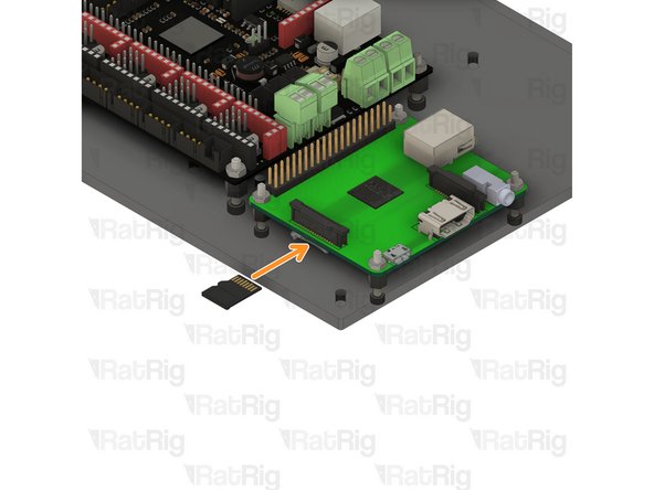
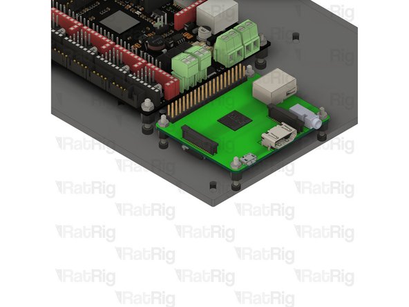
Prior to any further assembly, it is highly recommended to prepare the Raspberry Pi micro SD card with RatOS
-
Follow the Raspberry Pi Installation and WIFI sections on the RatOS website before continuing
-
Do not move on to the "Preparing your control board" section. This will be completed during Step 20
-
Once complete, insert the micro SD card into the Raspberry Pi 3a+ and proceed to the next step
-
Set this assembly aside until Step 17
-
-
-
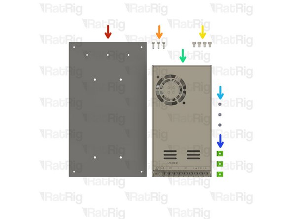
1x Electronics Panel - Power Supply
-
3x M3x10 Cap Head Screw
-
4x M4x6 Cap Head Screw
-
1x 24V Power Supply
-
3x M3 Nylon Locking Hex Nut
-
3x case_wire_holder printed part
-
-
-
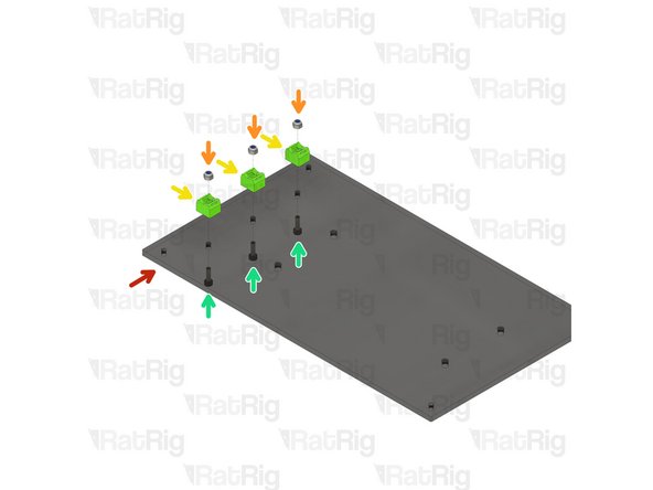
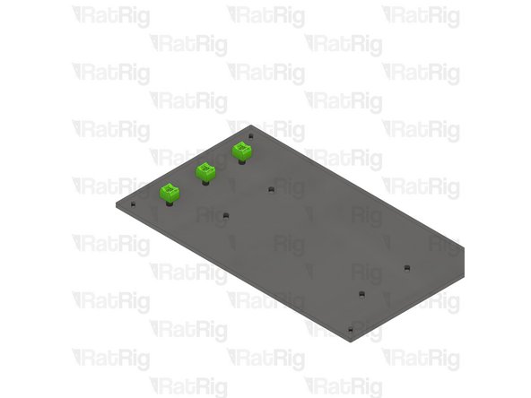
Electronics Panel - Power Supply
-
M3 Nylon Locking Hex Nut
-
case_wire_holder printed part
-
Install an M3 nylon locking nut into each case_wire_holder as shown
-
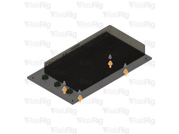
M3x10 Cap Head Screw
-
Fasten the case_wire_holders to the panel using the M3x10 screws
-
Take care not to over tighten the M3x10 screws as you can damage the printed parts
-
-
-
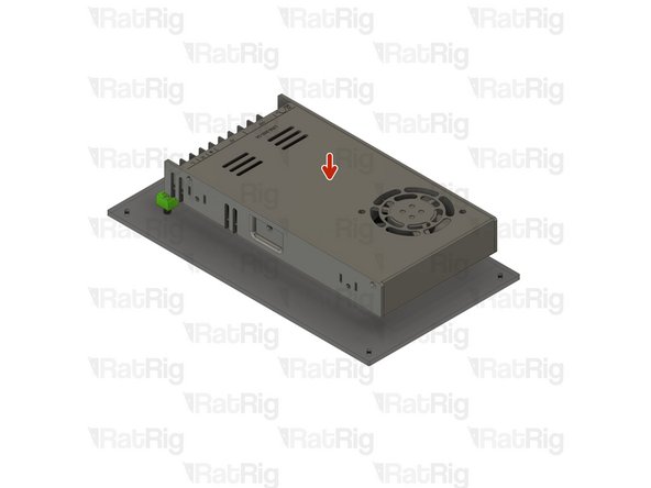
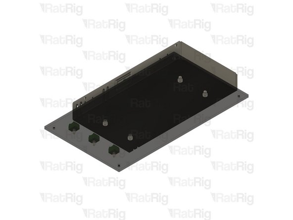
24V Power Supply
-
Align the holes on the underside of the power supply with the holes in the panel
-
M4x6 Cap Head Screw
-
Fasten the power supply to the panel by installing an M4x6 screw in each hole shown
-
Set this assembly aside until Step 21
-
-
-
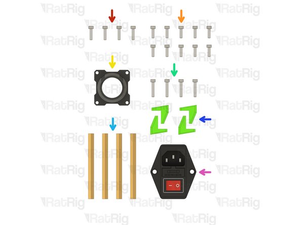
4x M3x12 Cap Head Screw
-
10x M3x10 Cap Head Screw
-
1x case_wire_passthrough printed part
-
4x M3x16 Cap Head Screw
-
4x M3x70 Brass Standoff
-
4x case_feet printed part
-
1x Fused & Switched IEC Socket
-
-
-
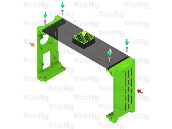
Assembly from Step 2
-
Assembly from Step 3
-
Assembly from Step 7
-
M3x10 Cap Head Screw
-
Fasten the three enclosure parts together using four M3x10 screws as shown
-
Take care not to over tighten the M3x10 screws as you can damage the printed parts
-
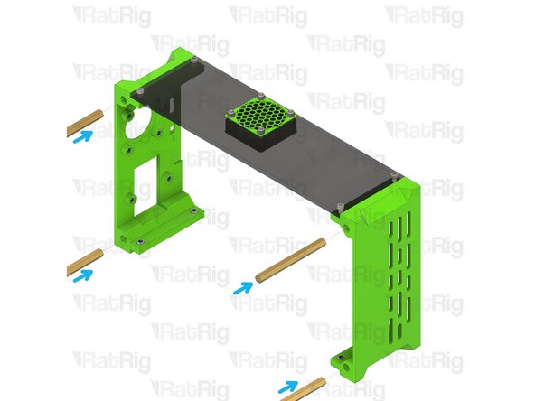
M3x70 Brass Standoff
-
Insert an M3x70 brass standoff into each of the holes shown
-
-
-
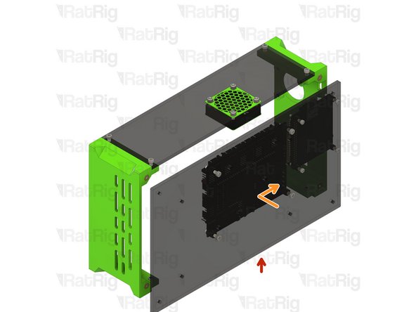
Assembly from Step 11
-
Install the electronics panel by placing it against the frame assembly whilst offset towards the front. Slide the panel to the rear until the ports on the Raspberry Pi 3a+ fit into the associated holes on the rear printed part
-
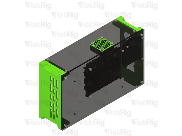
M3x10 Cap Head Screw
-
Fasten the electronics panel to the enclosure assembly using four M3x10 screws as shown
-
-
-
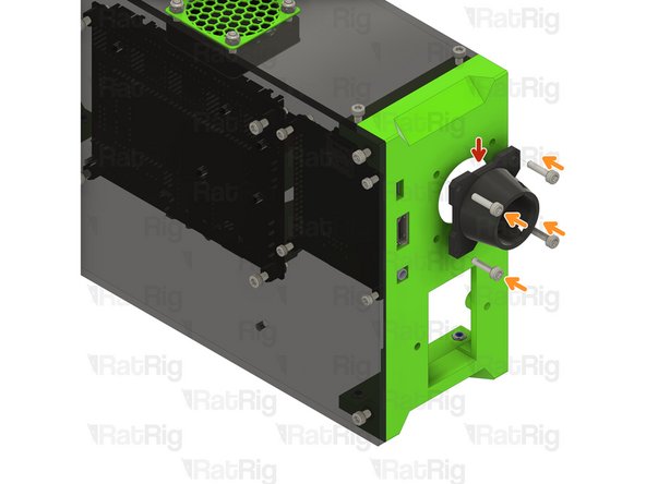
case_wire_passthrough printed part
-
M3x12 Cap Head Screw
-
Fasten the case_wire_passthrough to the enclosure rear using four M3x12 screws
-
Take care not to over tighten the M3x12 screws as you can damage the printed parts
-
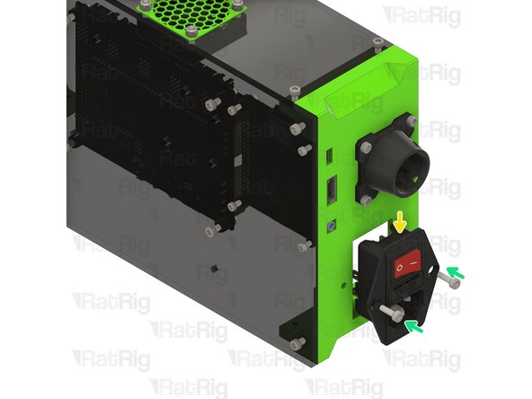
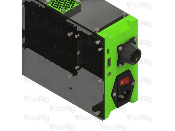
Fused & Switched IEC Socket
-
M3x10 Cap Head Screw
-
Fasten the IEC socket to the enclosure rear using two M3x10 screws
-
Take care not to over tighten the M3x10 screws as you can damage the printed parts
-
-
-
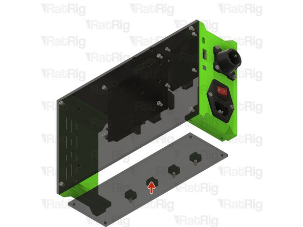
Assembly from Step 5
-
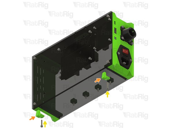
case_feet printed part
-
M3x16 Cap Head Screw
-
Insert an M3x16 screw through each foot, through the base panel and fasten to the enclosure assembly
-
Take care not to over tighten the M3x16 screws as you can damage the printed parts
-
-
-
Prior to continuing the assembly, the wiring must be completed and the SKR 2 / Octopus 1.1 motherboard needs to be prepared for RatOS
-
Mains electricity can cause serious harm or kill you. If you are not experienced working with mains electricity, consult a qualified electrician
-
The 24V power supply may need to be set to your local mains electricity voltage
-
There is a label on the power supply showing the location of the switch, and the position it must be set to depending on your whether your mains voltage is ~115V or ~230V
-
A full wiring diagram is provided in the electronics section of the V-Minion product site
-
After successfully wiring your electronics, you may proceed with the Preparing your Control Board section of the RatOS guide
-
Once the wiring is complete, and the SKR 2 / Octopus 1.1 is ready, proceed to the next step
-
-
-
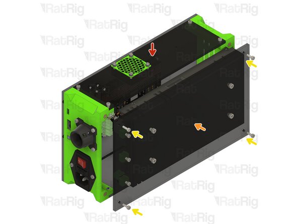
Assembly from Step 19
-
Assembly from Step 14
-
M3x10 Cap Head Screw
-
Fasten the power supply panel to the enclosure assembly using four M3x10 screws as shown
-
-
-
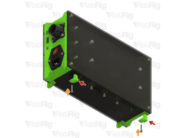
case_feet printed part
-
M3x16 Cap Head Screw
-
Insert an M3x16 screw through each foot, through the base panel and fasten to the enclosure assembly
-
Take care not to over tighten the M3x16 screws as you can damage the printed parts
-


Cancel: I did not complete this guide.
11 other people completed this guide.