Reputation over time
It looks like this user hasn't gained any reputation yet.
Once they have, you'll be able to view a graph of their reputation gained over time.
Here's a preview of what the graph will look like:
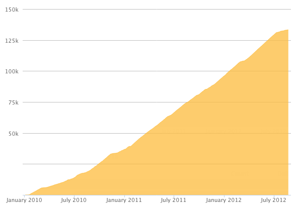
Reputation Breakdown
No reputation gained yet.
644
Having followed this guide upon first power up the Cooling Part fan was on 100%. You need to follow the RatOS config guide to reverse the PWM signal so on printer power up the Cooling Part fan starts Off. See details here https://os.ratrig.com/docs/guides/4028/
I have an Orbitor v2.0 and the cable length is too short to reach the Octopus mainboard. My solution was to use the short JST Female adaptor the Orbitor comes with, by cutting it off then soldering it to the 1 meter stepper motor wire.
For those less familiar, the JST2 connector should be written as JST-XH 2 Pin (2.54mm pitch) since the JST connectors come in a variety of sizes.
The second image has the blue dotted line coming from the 3rd connector from the top on the Octopus board, however it should be coming from the 2nd from the top.
As the Introduction states the following items I had to buy as they do not come with the kit;
4 x M4x6mm cap head screw (power supply)
4 x M4x10mm cap head screw (SSR relay)
8 x M4 locking hex nuts
4 x M3x16mm cap head screw (octopus)
4 x M2.5x16mm cap head screw (pi)
4 x M2.5 locking hex nut
The description states both 6mm and 10mm M4 screws. I believe the 10mm version is wrong and 6mm M4 screws should be used to mount as the depth of hole in the power supply is 3.5mm and with a 3mm thick electronics panel a 6mm screw will fit with a 0.5mm clearance and not bottom out on the power supply housing.
Rather than a M3 nylon hex nut, my part came printed for a heat insert to be installed instead.
The side with the sticker on the Axial Fan should face the heatsink of the Hotend so air is blown over the heatsink.
On the Rapido the wires are oriented to the right.
Should be "4x35mm Dowel Pin" and not 3x
Page 1 of 2
Next