Reputation over time
It looks like this user hasn't gained any reputation yet.
Once they have, you'll be able to view a graph of their reputation gained over time.
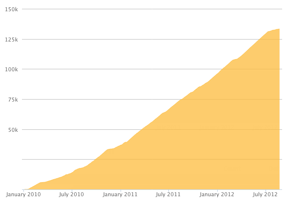
Here's a preview of what the graph will look like:
Reputation Breakdown
No reputation gained yet.
652
What is the different between Step 48 & Step 49 + Step 50 & Step 51? Seems like there are duplicates...
Here is a small mistake: "Check once again if the jumper is placed in the right position to supply 12V to the Fan - Step 3"
But it's in Step 5...
Here is my configuration for the cooling fan “SANYO DENKI 12V 9GAX0412P3S001” with 4 wires:
+ red = J56
- black = J56
PWN (control) brown = J50 (PA8) > must be reversed in the printer.cfg to "!PA8"
RPM (pulse sensor) yellow = DIAG4 (PG12)
(Jumper is set only on J56 to 12V)
printer.cfg
[fan]
pin: !PA8
max_power: 1.0
shutdown_speed: 0
cycle_time: 0.010
hardware_pwm: False
kick_start_time: 0.100
off_below: 0.0
tachometer_pin: PG12
tachometer_ppr: 2
tachometer_poll_interval: 0.0015
#enable_pin:
Important: The Octopus V1.1 board and a Pi4 only works with the original USB cable that came in the box.
Otherwise the following error message will appear:
klippy.log
mcu 'mcu': Unable to open serial port: [Errno 2] could not open port /dev/btt-octopus-11: [Errno 2] No such file or directory: '/dev/btt-octopus-11'
moonraker.log
[klippy_connection.py:_check_ready()] - mcu 'mcu': Unable to connect
The picture shows a 24V jumper for a 12V cooling fan on J50... no jumper on J50 (!PA8) is required for the cooling fan!
Only with J56 does the jumper have to be set.
The picture shows a 24V jumper on J50... no jumper on J50 (!PA8) is required for the cooling fan!
Only with J56 does the jumper have to be set.
The picture shows a jumper on J50... no jumper on J50 (!PA8) is required for the “SANYO DENKI 12V 9GAX0412P3S001”!
Only with J56 does the jumper have to be set to 12V.
If you plan to mount the electronic components with DIN Rails, then follow my collection on printables.com:
https://www.printables.com/de/model/6976...
Because now longer screws have to be used:
8x M6x12mm > M6x22mm Cap Head Screws (based on a 4mm electronics panel).
If you plan to mount the electronic components with DIN Rails, then follow my collection on printables.com:
https://www.printables.com/de/model/6976...
Because now longer screws have to be used:
8x M6x12mm > M6x22mm Cap Head Screws (based on a 4mm electronics panel).
For setup of V-CORE 400:
The documentation says „Insert an M3x12 screw in every other hole in the linear rail“.
But all following pictures shows install one screw every second hole…
The requirements says: "400x400: 2x 450mm, 3x 500mm, 48x M3x12 Screw, 48x 3030 T-Nuts"
So one screw every second hole was correct.
Is that correct? Please advise!
Page 1 of 2
Next