Reputation over time
It looks like this user hasn't gained any reputation yet.
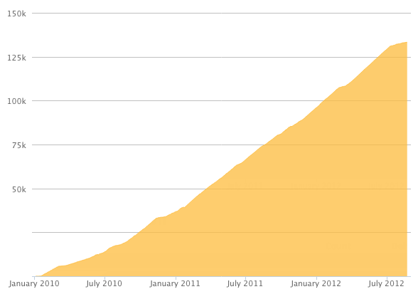
Once they have, you'll be able to view a graph of their reputation gained over time.
Here's a preview of what the graph will look like:
Reputation Breakdown
No reputation gained yet.
742
No mention of the acrylic lead wiring cover or the printed fan shroud for the Octopus?
This would be a great point to connect the Phaetus power lines to that green connector on the CAN board. It's a wicked tight angle to manage if done later.
This would be a great point to change and cut the Phaetus wires, while it can still be done as bench work. Doing this later as guided is considerably more effort and opportunity for error.
How much of the belt should be sticking out? You say to cut it, but don't specify a target length.
This would be a great point to change the plug on the fan- while it can still be done as bench work. It's considerably more difficult to do later on as guided.
I think that's meant to be "IF V-Core 4 400 and 500 ONLY 110V" you should double/triple check the voltage input switch, and use a power cable rated for 20A. I've read some folks on the Discord server mentioning the 400/500 units can help you trip your breakers :)
Why is #3 no longer shown in blue as above?
So here's a confusing color matter- earlier it says the yellow (in my case white) line out from the fan is not used on the Octopus board. Then the image that follows shows a white wire coming out of position #3. That means that the blue line out from the fan in block position #3 will be what now connects to a white wire. Probably it'd be good to say so. If you are simply thinking of connectivity, you'd probably think red to red, black to black, and white to white, not white to blue which is what you're really doing with connection #3.
While I also have no love for JST connectors, would this not be easier all around if we took off (or didn't yet install) the EBB board? Getting the heater wires to make a right angle entry from a closed off space seems needlessly challenging. I have to think there's an easier way of getting these steps done.
Quoting for helpfulness:
The Z0 Stepper must be connecter to driver 6.
Z0 is the front left stepper, when looking at the machine from the front.
The Z1 Stepper must be connecter to driver 7.
Z1 is the rear stepper, when looking at the machine from the front.
The Z2 Stepper must be connecter to driver 8.
Z2 is the front right stepper, when looking at the machine from the front.
Sebastian Krzakowski - Aug 11, 2024
Page 1 of 3
Next