Reputation over time
It looks like this user hasn't gained any reputation yet.
Once they have, you'll be able to view a graph of their reputation gained over time.
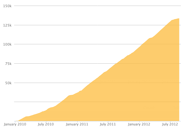
Here's a preview of what the graph will look like:
Reputation Breakdown
No reputation gained yet.
776
@ratrig Heatset inserts are not mentioned in the instructions, but seem to be missing in this part. It's unclear if there should be 4 or 6.
2 each:
- at the top of the arm
- on the left side for mounting vc4_arm_cable printed part
- Maybe also on the right side? The 2ⁿᵈ image in step 20 seems to show them, but I'm not sure.
Note: The inserts must be rotated by 90° (not 45°, which is physically impossible).
The requirement for rotating the POM Inserts should be mentioned in step 12 already!
Slighty disappointed by the fact, that the arms are not in punkfill gooey green. Slightly more annoyed, that I was searching for gooey green parts for quite a while before realising that they came in black.
@ratrig The images should be updated, or at least clearly noted that these parts can come in either colour!
One of my POM Arm Inserts come with a broken off corner. I hope this isn't a problem later on.
The fit of these pieces is extremely tight, the clearance in the printed parts is just too small. Without Ben White's trick with using a longer M16×16 screw, you don't have any chance of pulling these in. Given the slanted surfaces you cannot push them in with a vice either.
@ratrig Also annoying that the missing heat-inserts aren't mentioned in the assembly steps. I was delighted when I heard that all heatset inserts come pre-installed. (So I could skip buying equipment for that.) Withou MoJo's comment, I clearly would have missed that these inserts are not preinstalled. Are M3×4×4.6 (SKU HW3224NC) the correct ones?
Do not build two identical arms!
The note in step 14 says: The POM insert must be rotated 45º compared to the previous (in this step 12) assembly
If you decide to do the Z-Motor cable routing now check the cable clips to affix the motor-wires as instructed in Chapter 12, Step 46.
You can check cable preparation and cable routing in Chapter 12, Steps 52 and 53.
For the 500mm model the cable lengths are:
- Rear motor: 1520mm
- Front motors: 2060mm
Don't forget to label the cable ends after guiding them through the base-plate hole/rubber grommet, so you know which one is which after tilting the frame upright again.
The bag with the thrust bearings is labelled: Thrust Bearing F8-16M (SKU: HW2118WC)
It contains three sub-bags which each contain
- 2 × silver washers (6 washers in total)
- 1 × brass ball cage with captivated bearing-balls (3 cages in total)
The bag with the rigid couplers is labelled: Coupler Rigid Type BLK (SKU: HW2990GC)
You can find the robber grommet in a separate small bag in the large metal-hardware bag.
It's labeled: Rubber Grommet 18×14×3, SKU:HW3783GC
For the 500mm model:
- the front base plate does not have a front/center hole.
Page 1 of 2
Next