Steps
19

In Progress
This guide is currently being written. Reload periodically to see the latest changes.

User-Contributed Guide
This guide is not managed by the site's staff.

Private
This guide will not appear in search results and can only be viewed by team members!
Quiz
0
-
-
It is recommended to have the following tools available for assembling the Compact CNC Electronics Enclosure:
-
Allen Key / Hex Wrenches in the following sizes: 2mm, 3mm & 5mm
-
Wire cutters & a wire stripper
-
Crimping tool (JST-XH, Molex-Micro fit and 18-14AWG Fork + Spade terminals)
-
Cross slot / phillips and flat screwdrivers
-
Soldering Iron with an M3 heat insert tip
-
-
-
The following printed parts need preparation:
-
4x compact_cnc_electronics_corner printed part
-
2x compact_cnc_electronics_btt_rodent printed part
-
2x compact_cnc_electronics_psu printed part
-
This part also has sacrificial layers which need to be cleared
-
36x M3 heat insert
-
-
-
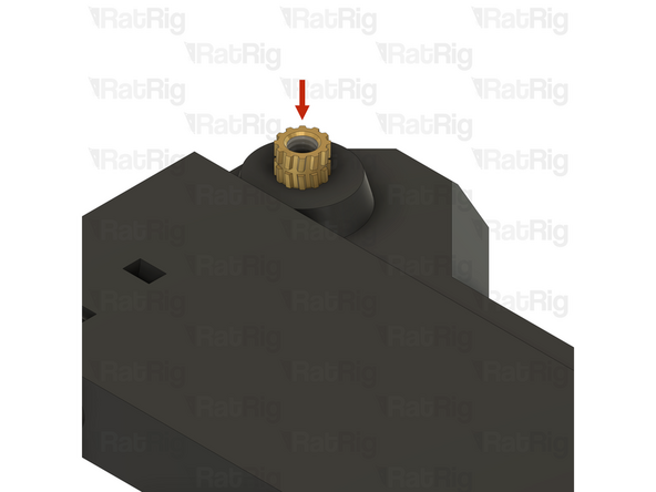
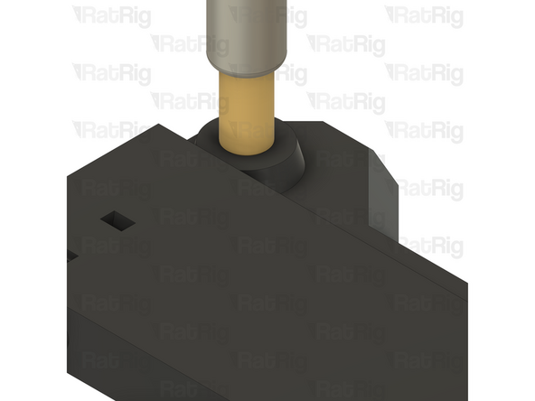
These steps show how to install an M3 heat insert into the printed parts
-
M3 heat insert
-
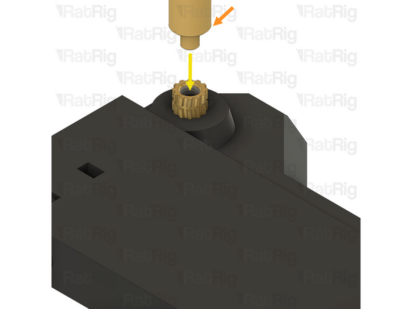
Soldering iron with M3 heat insert tip
-
Align the soldering iron tip with the heat insert
-
Be careful not to burn yourself!
-
-
-
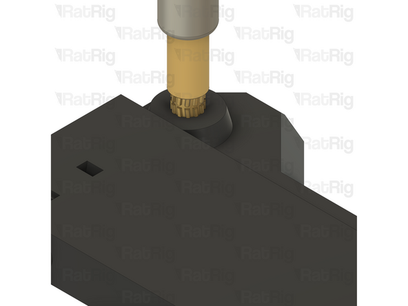
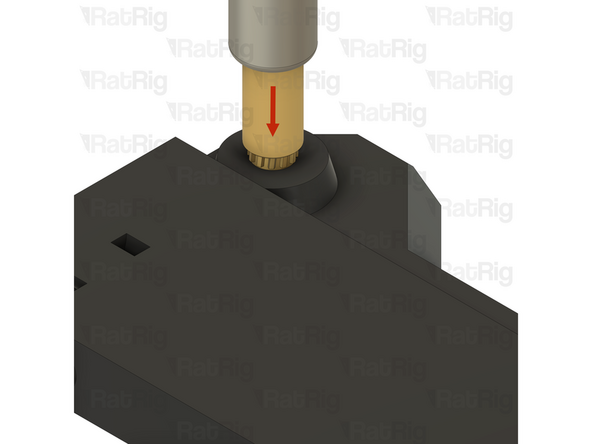
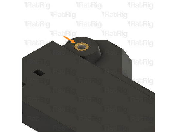
Slowly press the heat insert into the printed part
-
Ensure the heat insert is flush with the printed part, or even a little below the surface
-
Avoid having a heat insert higher than the printed part, this can cause assembly issues
-
Remove the soldering iron
-
Be careful not to burn yourself!
-
-
-
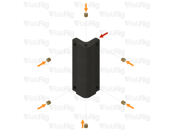
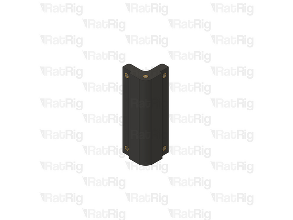
compact_cnc_electronics_corner printed part
-
M3 heat insert
-
Install the M3 heat inserts into the indicated holes
-
Repeat for all 4 compact_cnc_electronics_corner printed parts
-
Set these assemblies aside until Step 19
-
-
-
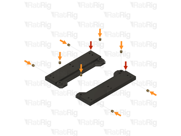
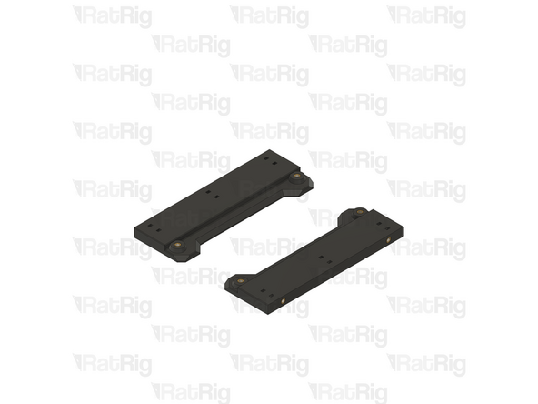
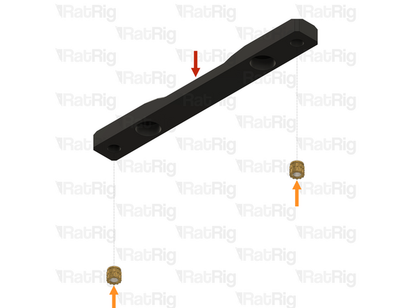
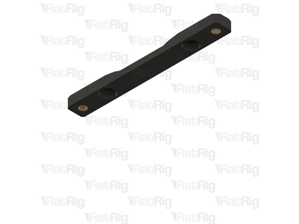
compact_cnc_electronics_btt_rodent printed part
-
M3 heat insert
-
Install the M3 heat inserts into the indicated holes
-
Set these assemblies aside until Step 17
-
-
-
compact_cnc_electronics_psu printed part
-
M3 heat insert
-
Install the M3 heat inserts into the indicated holes
-
Repeat for both compact_cnc_electronics_psu printed parts
-
Set these assemblies aside until Step 15
-
-
-
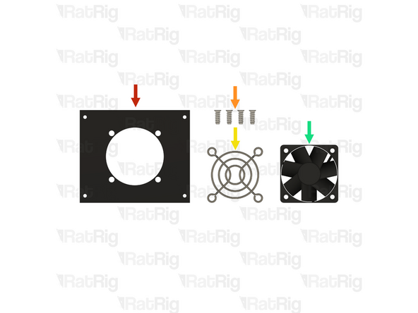
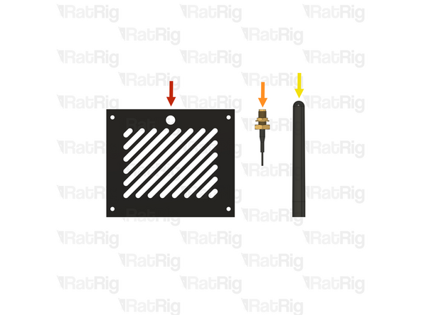
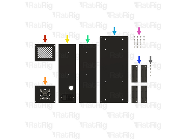
1x compact_cnc_rear_cooling_panel
-
4x Self tapping screw - fan - 12mm
-
1x 50mm fan grille
-
1x 50x15mm 24V fan
-
-
-
4x Self tapping screw - fan - 12mm
-
1x 50mm fan grille
-
1x compact_cnc_rear_cooling_panel
-
1x 50x15mm 24V fan
-
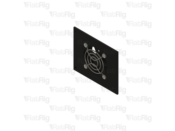
Insert the screws through the fan grille, through the panel, and then thread them into the fan body
-
Set this panel assembly aside until Step 19
-
-
-
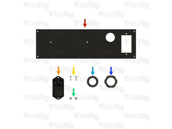
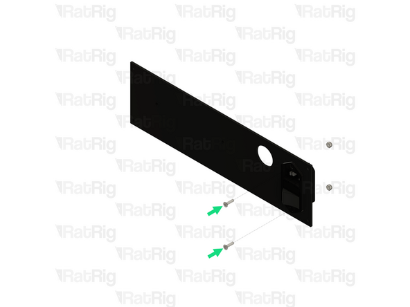
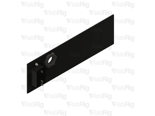
1x compact_cnc_left_panel
-
1x Switchable & fused IEC inlet
-
2x M3x12 Countersink screw
-
2x M3 locking hex nut
-
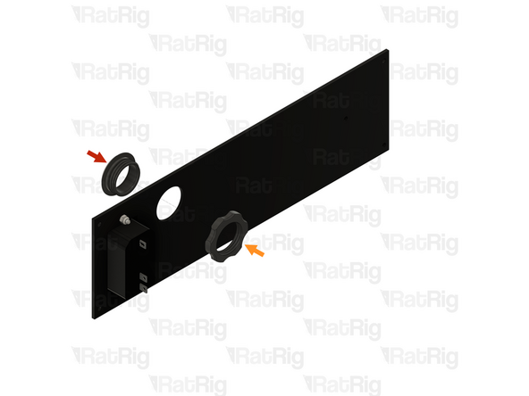
1x compact_cnc_electronics_panel_collar printed part
-
1x compact_cnc_electronics_panel_collar_nut printed part
-
-
-
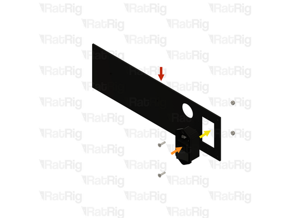
1x compact_cnc_left_panel
-
1x Switchable & fused IEC inlet
-
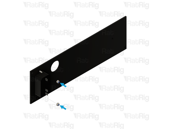
Insert the IEC inlet into the panel as shown
-
2x M3x12 Countersink screw
-
2x M3 locking hex nut
-
Tighten the M3 screws to secure the IEC inlet to the panel
-
-
-
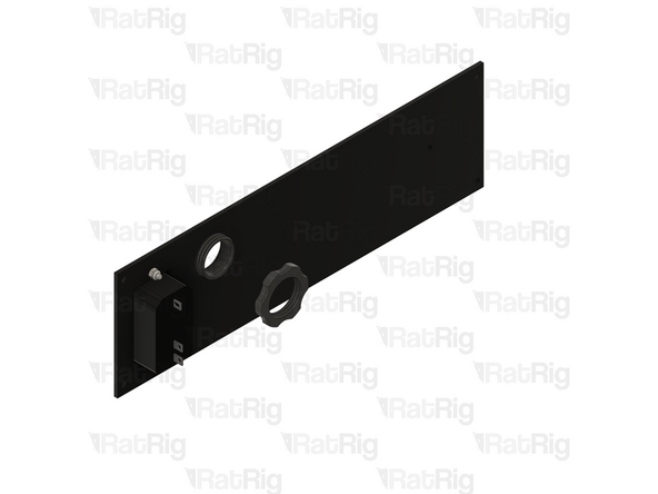
1x compact_cnc_electronics_panel_collar printed part
-
1x compact_cnc_electronics_panel_collar_nut printed part
-
Do not overtighten the printed nut as you can damage the printed parts
-
Set this panel assembly aside until Step 19
-
-
-
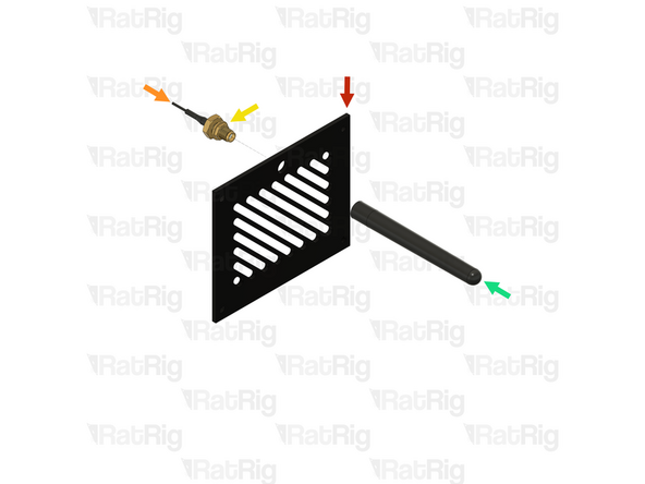
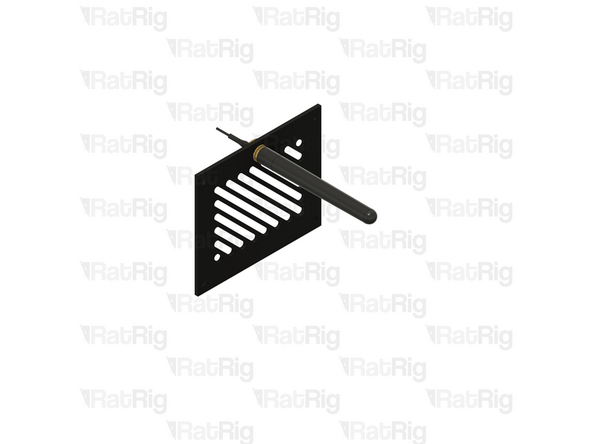
1x compact_cnc_top_panel
-
1x IPEX to SMA female WiFi pigtail
-
1x SMA 2.4GHz Wifi antenna
-
-
-
1x compact_cnc_top_panel
-
1x IPEX to SMA female WiFi pigtail
-
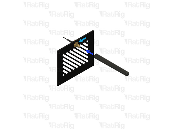
Remove the marked nut from the WiFi pigtail, then insert the pigtail into the panel
-
1x SMA 2.4GHz Wifi antenna
-
Secure the WiFi pigtail to the panel by reinstalling the nut
-
Screw the WiFi antenna onto the WiFi pigtail
-
Set this panel assembly aside until Step 19
-
-
-
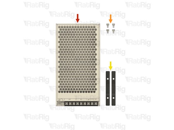
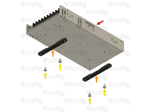
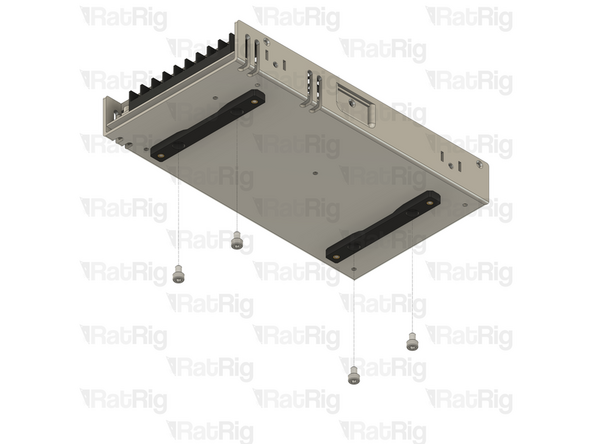
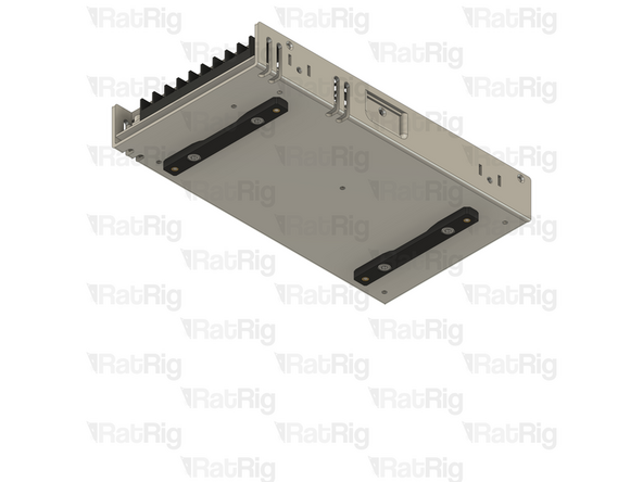
1x Weho LRS-250-24 fanless PSU
-
4x M4x6 cap head screw
-
2x PSU mount assemblies from Step 7
-
-
-
1x Weho LRS-250-24 fanless PSU
-
2x PSU mount assemblies
-
4x M4x6 cap head screw
-
Align the PSU mounts with the holes on the PSU. Secure them to the PSU using the M4x6 cap head screws
-
Take care not to over-tighten the screws as you can damage the printed parts
-
Set the PSU assembly aside until Step XX
-
-
-
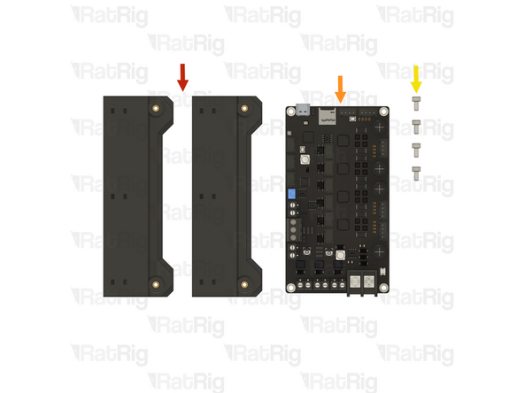
2x Rodent mount assemblies from Step 6
-
1x BIGTREETECH Rodent CNC Controller
-
4x M3x6 cap head screw
-
-
-
2x Rodent mount assemblies
-
1x BIGTREETECH Rodent CNC controller
-
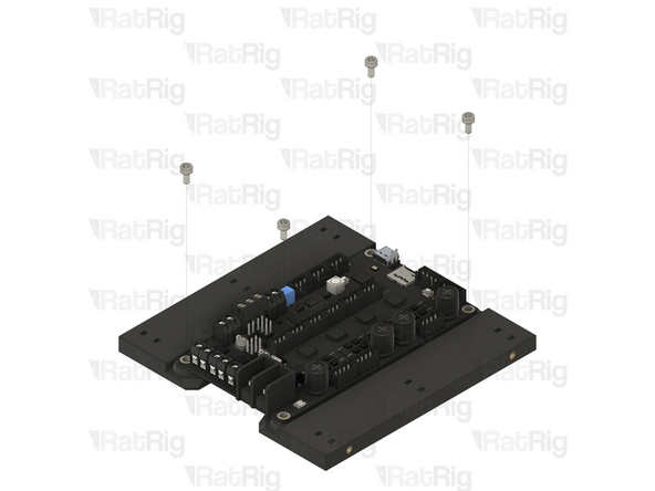
4x M3x6 cap head screw
-
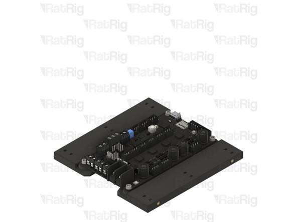
Align the BTT Rodent CNC controller with the holes on the mounts. Secure the controller to the mounts using the M3x6 cap head screws
-
Take care not to over-tighten the screws as you can damage the printed parts or the controller
-
Set the controller assembly aside until Step XX
-
-