Introduction
This section of the guide will step you through preparing all of the printed parts, and wiring, necessary to assemble the V-Core 4. This includes removing any support material, clearing sacrificial layers, and installing any threaded heat inserts into the printed parts, as well as crimping and assembling the necessary wiring.
If a printed part is not mentioned in this section of the guide, then no preparation steps are needed, and it is ready to use as is.
-
-
The following tools are required for this section of the guide:
-
A soldering iron
-
Heat insert tips for the soldering iron are recommended and will make installation easier
-
The V-Core 4 kit uses M2.5, M3 and M4 sized heat inserts
-
The following tools are recommended for this section of the guide:
-
An electric, or hand drill & drill bits in the sizes of 3mm and 4mm
-
A drill, and correctly sized drill bits will help with clearing sacrificial layers on some printed parts
-
Cyanoacrylate glue
-
-
-
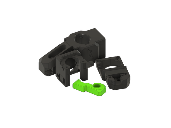
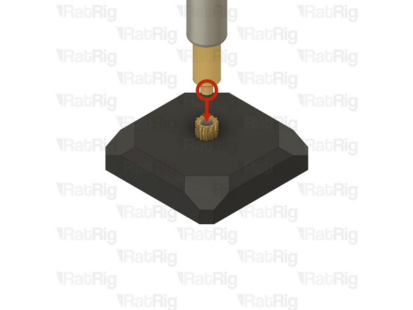
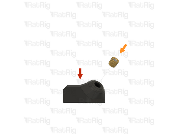
These steps show how to install a heat insert into the printed parts, the instructions are the same for all heat insert sizes
-
Example printed part
-
Heat insert
-
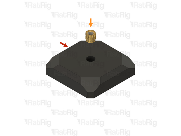
Insert the thinner end of the heat insert into the printed part hole as shown
-
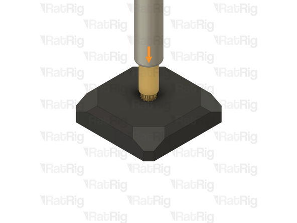
Soldering iron with matching size heat insert tip
-
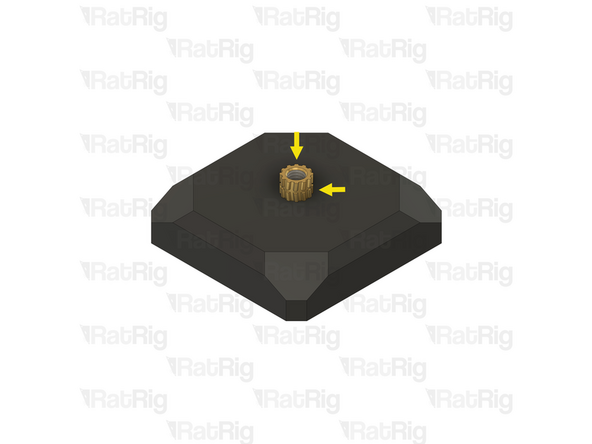
Rat Rig printed parts are made from ABS, it is recommended to set your soldering iron to 265°C to install the heat inserts
-
Do not use a temperature higher than 280C as this can cause the ABS to release harmful fumes
-
Be careful not to burn yourself
-
-
-
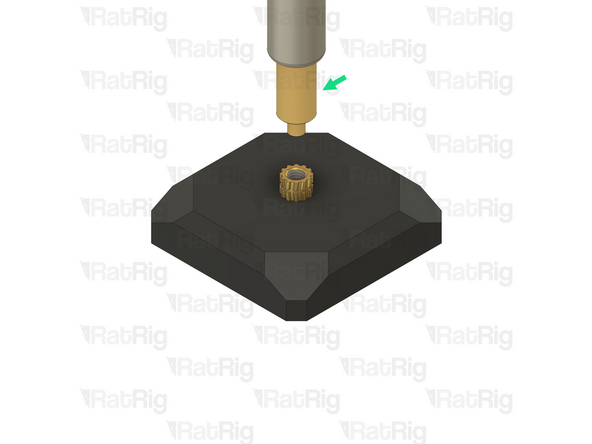
The protrusion on the heat insert tool should align with, and fit inside the heat insert as shown
-
Apply gentle downward pressure to guide the heat insert into the printed part
-
Keep the soldering iron perpendicular to the printed part, otherwise the insert could end up installed at an angle
-
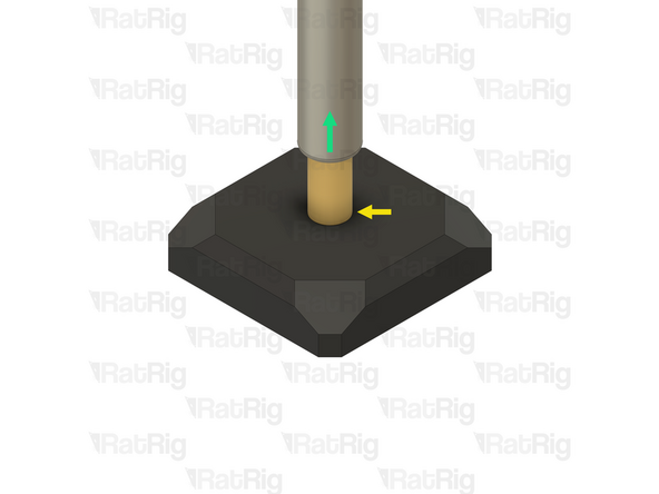
Keep applying downward pressure until the heat insert is flush with the printed part, or even a little recessed into it
-
Once the heat insert is fully inserted, gently remove the soldering iron straight upwards
-
Be careful not to burn yourself
-
-
-
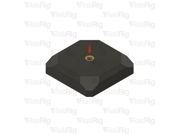
Installed heat inert
-
The heat insert will remain extremely hot for a short time, allow it to fully cool before touching it
-
Verify that the heat insert is flush with the printed part, or even a little recessed into it
-
If the heat insert is still proud of the printed part, you can use the soldering iron to heat it back up and push it further into the part
-
-
-
Although Rat Rig tries to avoid sacrificial layers where possible, several of the V-Core 4 printed parts have sacrificial layers which need to be removed prior to assembly
-
It is recommended to remove the sacrificial layers by using a correctly sized drill
-
If a drill is not available, then the sacrificial layers can be removed using a screwdriver or a hex key
-
Example printed part with sacrificial layers
-
Sacrificial layers to be cleared
-
Prepared printed part
-
-
-
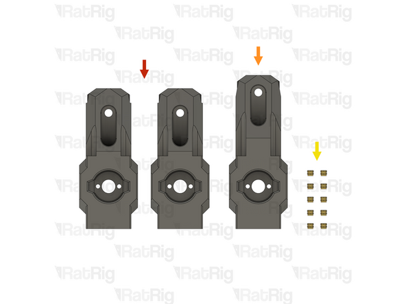
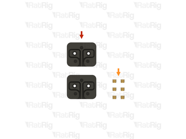
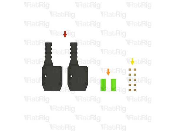
2x vc4_arm_front (SKU: PP000265)
-
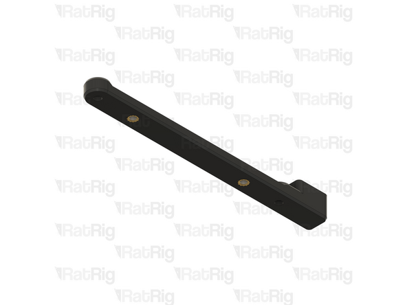
1x vc4_arm_rear (SKU: PP000266)
-
10x M3 heat insert (SKU: HW3224NC)
-
-
-
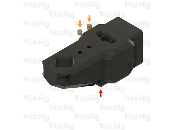
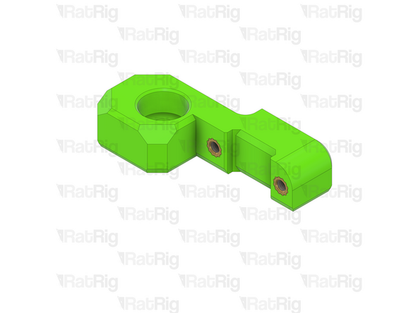
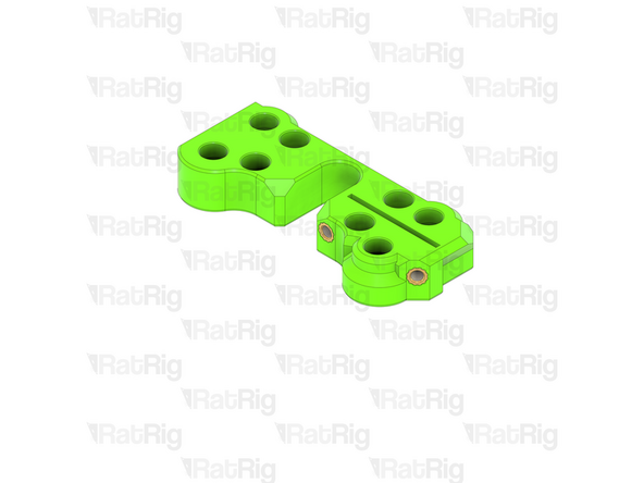
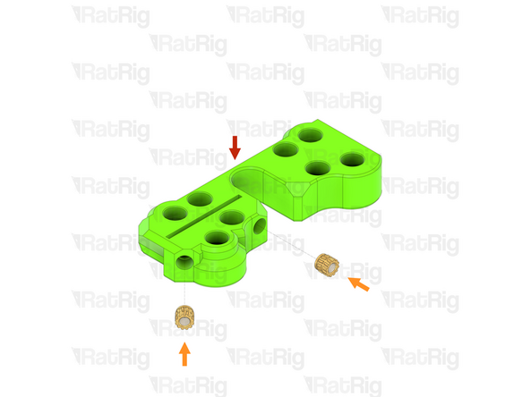
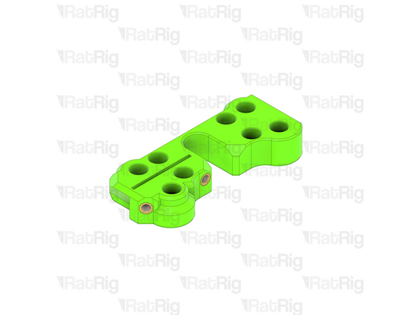
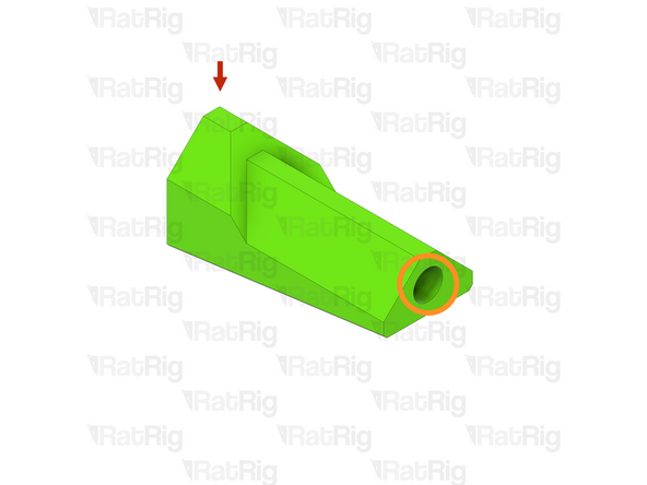
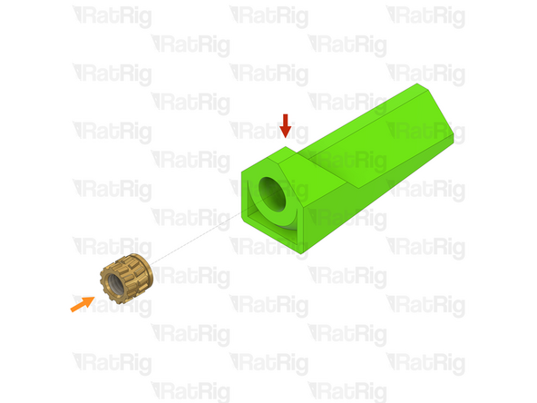
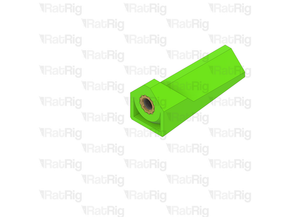
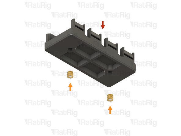
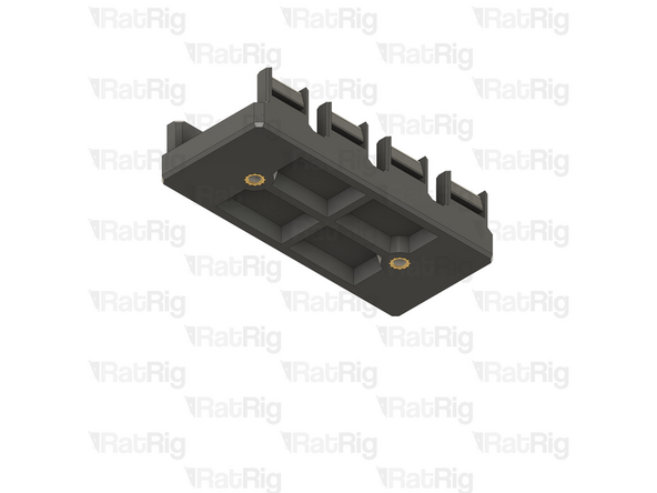
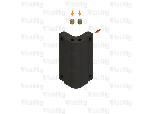
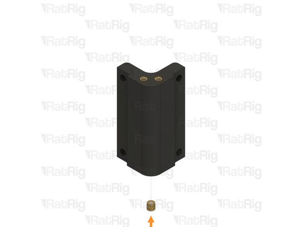
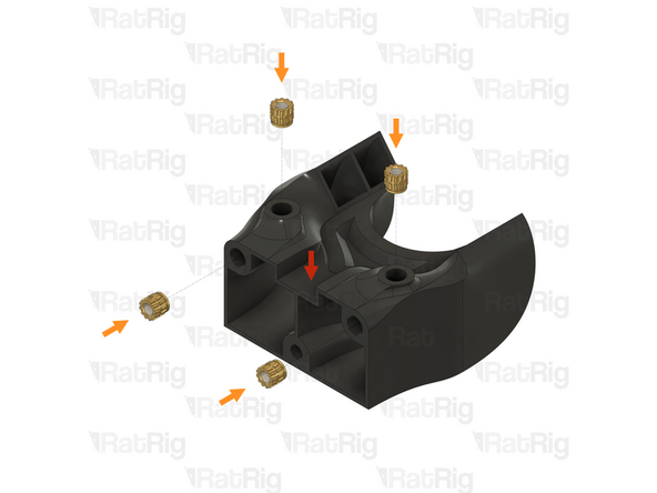
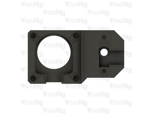
1x vc4_arm_front
-
2x M3 heat insert
-
Install an M3 heat insert into each of the marked holes
-
Prepare two of these printed parts
-
-
-
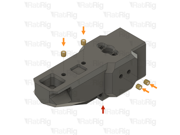
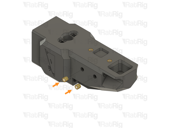
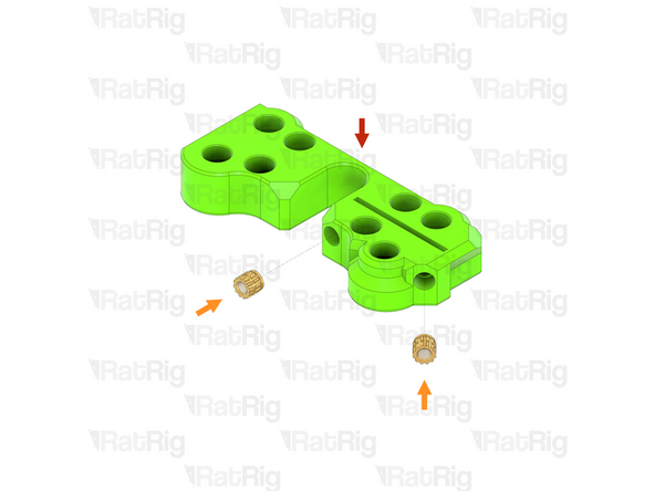
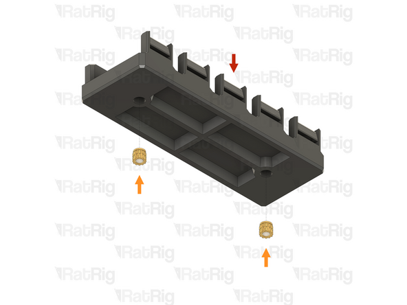
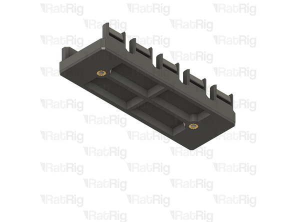
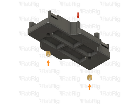
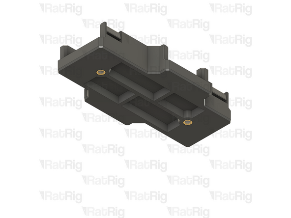
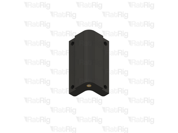
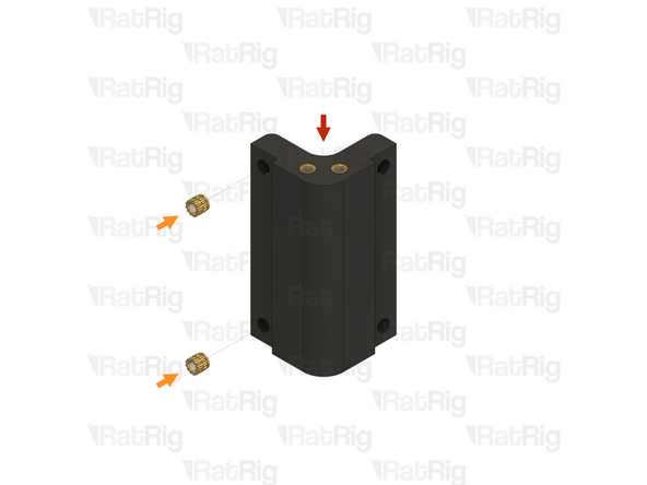
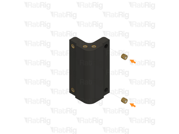
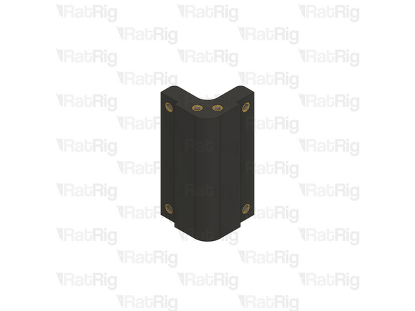
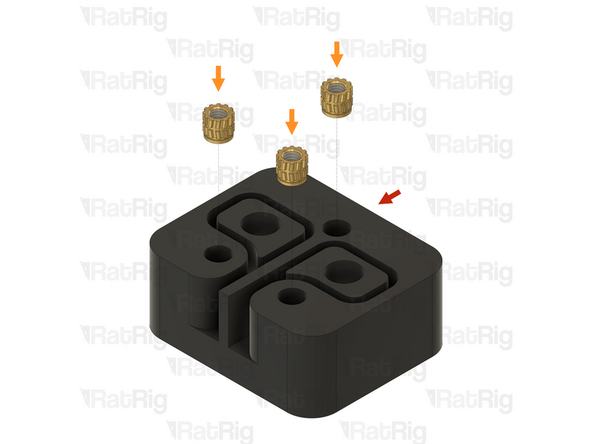
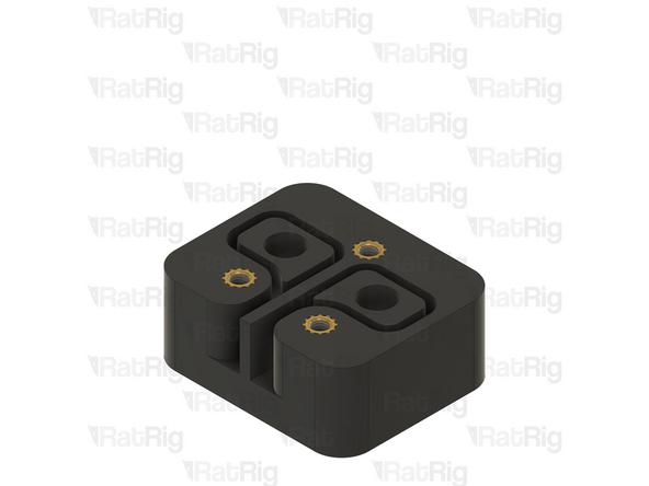
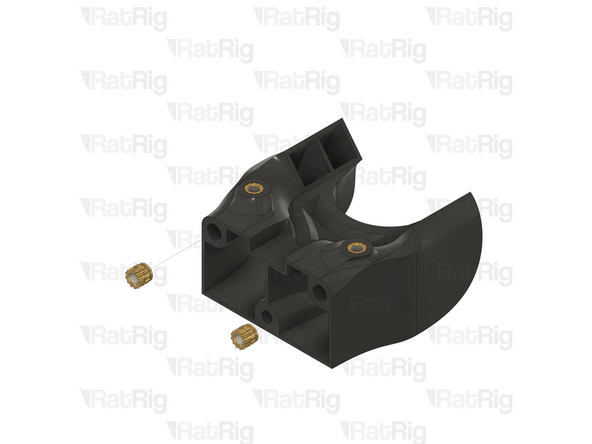
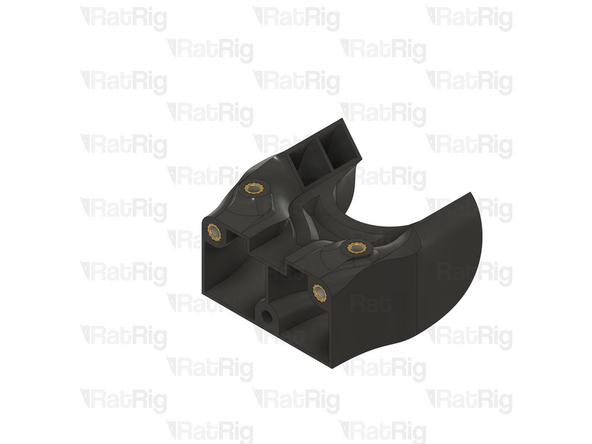
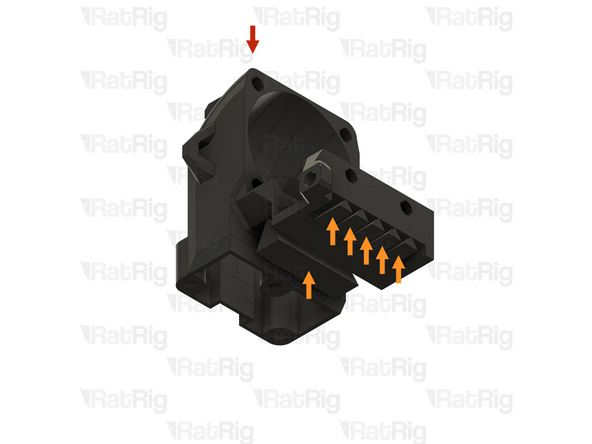
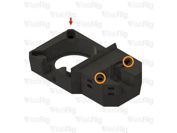
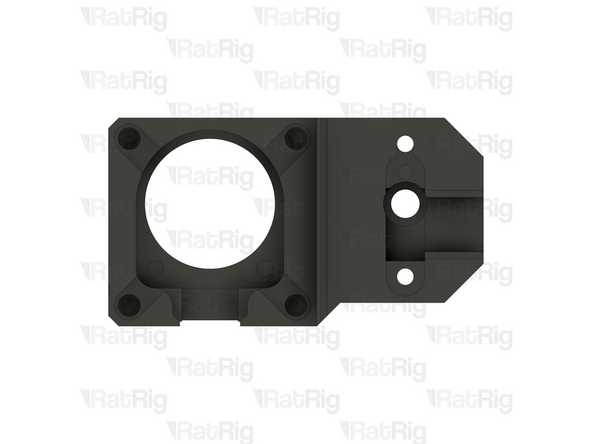
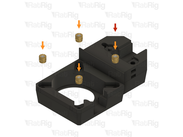
1x vc4_arm_rear
-
6x M3 heat insert
-
Install an M3 heat insert into each of the marked holes
-
-
-
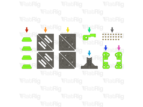
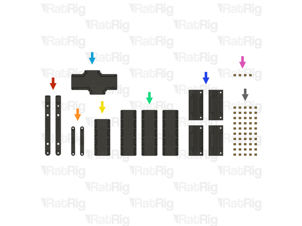
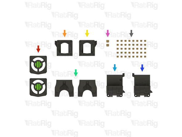
4x vc4_3060_trim_diffuser (SKU: PP000333)
-
4x vc4_3060_trim_front (SKU: PP000323)
-
4x vc4_3060_trim_rear (SKU: PP000324)
-
1x vc4_y_endstop_mount (SKU: PP000278)
-
1x vc4_umbilical_frame (SKU: PP000283)
-
1x vc4_xy_trim_left (SKU: PP000295)
-
1x vc4_xy_trim_right (SKU: PP000296)
-
23x M3 heat insert (SKU: HW3224NC)
-
-
-
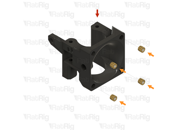
1x vc4_3060_trim_front
-
2x M3 heat insert
-
Install an M3 heat insert into each of the marked holes
-
Prepare four of these printed parts
-
-
-
1x 3030 trim front assembly from the previous step
-
Cyanoacrylate glue
-
Apply a drop of cyanoacrylate glue in the spots marked
-
1x vc4_3060_trim_diffuser
-
Insert the vc4_3060_trim_diffuser into the 3060 trim front as shown
-
Apply a gentle downward pressure on the diffuser for a minute to allow the cyanoacrylate glue to set
-
Prepare four of these printed parts
-
-
-
1x vc4_3060_trim_rear
-
2x M3 heat insert
-
Install an M3 heat insert into each of the marked holes
-
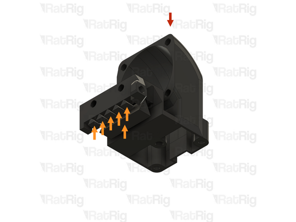
Clear the sacrificial layers from the two marked holes
-
The sacrificial layers may not be present. If they are, it is recommended to use a 3mm drill to clear them
-
Prepare four of these printed parts
-
-
-
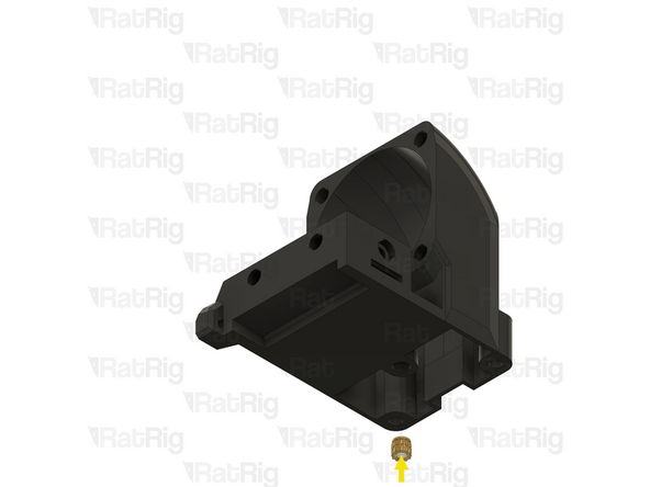
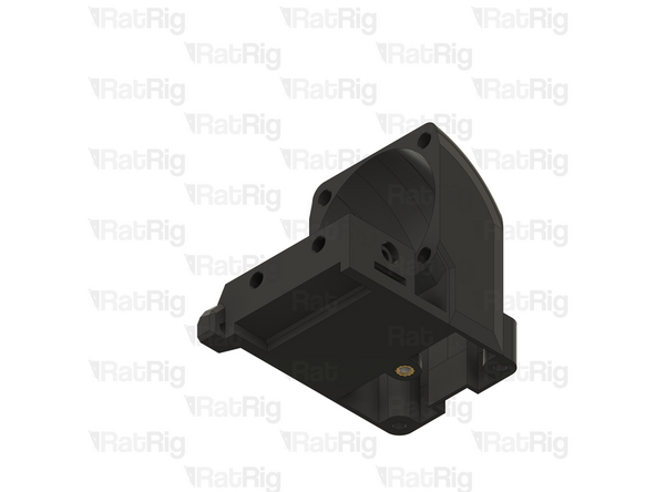
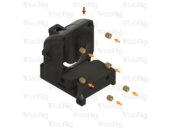
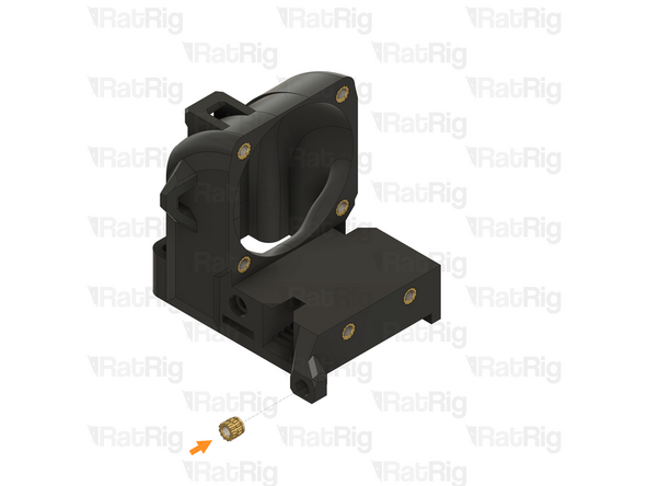
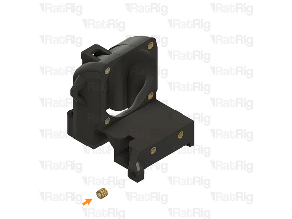
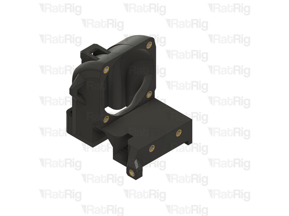
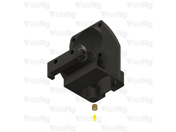
1x vc4_y_endstop_mount
-
2x M3 heat insert
-
Install an M3 heat insert into each of the marked holes
-
-
-
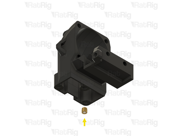
1x vc4_umbilical_frame
-
1x M3 heat insert
-
Install an M3 heat insert into the marked hole
-
-
-
1x vc4_xy_trim_left
-
2x M3 heat insert
-
Install an M3 heat insert into each of the marked holes
-
-
-
1x vc4_xy_trim_right
-
2x M3 heat insert
-
Install an M3 heat insert into each of the marked holes
-
-
-
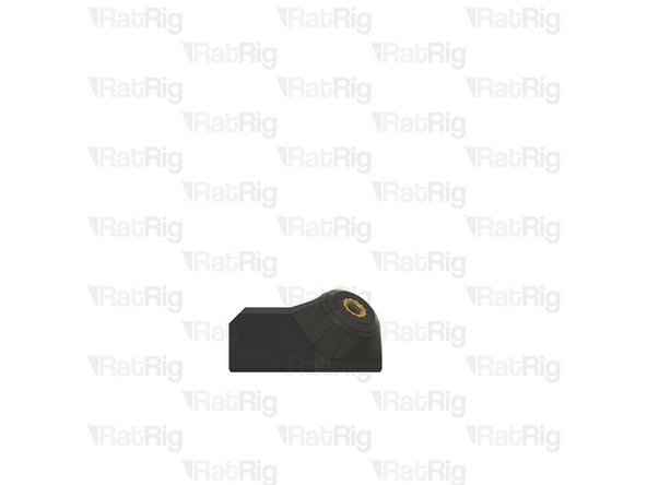
1x vc4_led_holder_frame
-
1x M3 heat insert
-
Install an M3 heat insert into the marked hole
-
Prepare four of these parts
-
-
-
If you are building a CoreXY or Hybrid variant of the V-Core 4.0, then please continue following the next steps
-
If you are building an IDEX variant of the V-Core 4.0, then please skip to preparing the electronics enclosure printed parts
-
-
-
1x rr_toolhead_vc4_shroud (SKU: PP000331)
-
1x rr_toolhead_vc4_duct (SKU: PP000312)
-
1x rr_toolhead_vc4_front_beacon (SKU: PP000334)
-
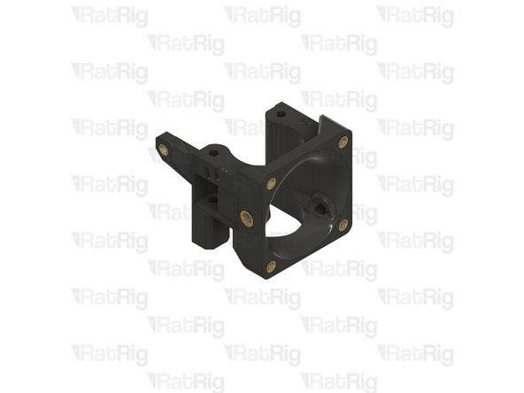
1x rr_toolhead_vc4_back (SKU: PP000308)
-
1x rr_toolhead_vc4_toolboard_vertical (SKU: PP000325)
-
2x rr_toolhead_vc4_back_clamp (SKU: PP000309)
-
25x M3 heat insert (SKU: HW3224NC)
-
2x M4 heat insert (SKU: HW3791NC)
-
-
-
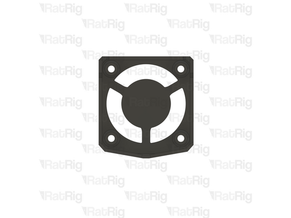
1x rr_toolhead_vc4_shroud
-
Clear the sacrificial layers from the four marked holes
-
It is recommended to use a 3mm drill to clear the sacrificial layers
-
-
-
1x rr_toolhead_vc4_duct
-
2x M3 heat insert
-
Install an M3 heat insert into each of the marked holes
-
-
-
1x Duct assembly from the previous step
-
4x M3 heat insert
-
Install an M3 heat insert into each of the marked holes
-
-
-
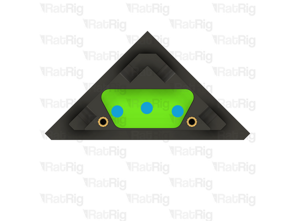
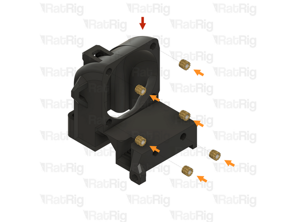
1x rr_toolhead_vc4_front_beacon
-
5x M3 heat insert
-
Install an M3 heat insert into each of the marked holes
-
-
-
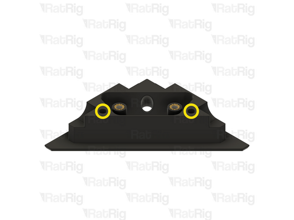
1x Front assembly from the previous step
-
1x M4 heat insert
-
Install an M4 heat insert into the marked hole
-
Remember to change the heat insert tip in the soldering iron for the M4 sized tip
-
Allow the soldering iron to cool before changing the tips
-
-
-
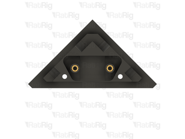
1x Front assembly from the previous step
-
1x M4 heat insert
-
Install an M4 heat insert into the marked hole
-
-
-
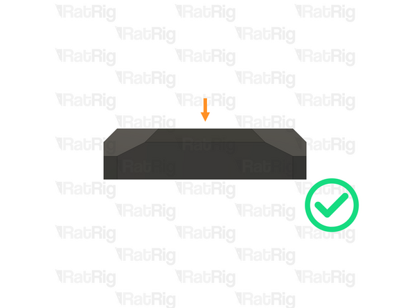
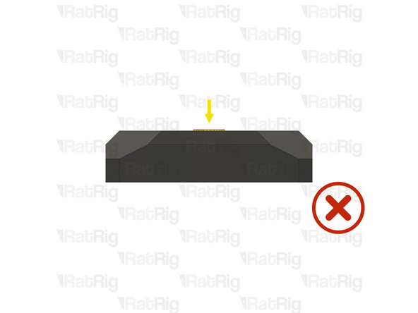
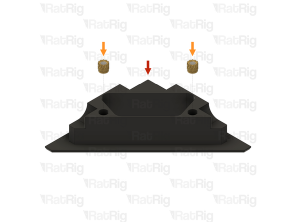
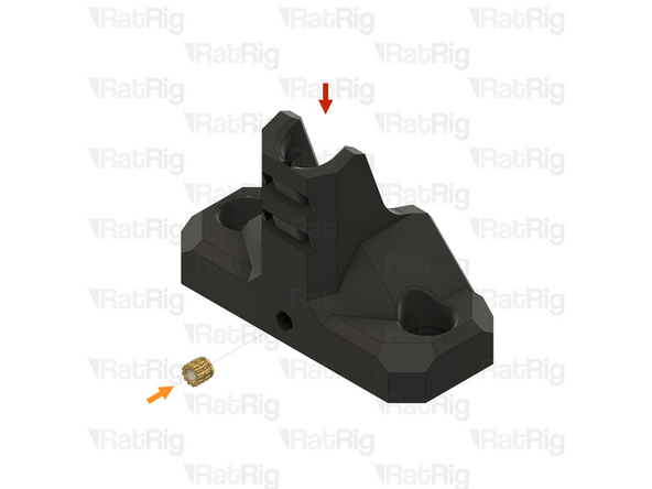
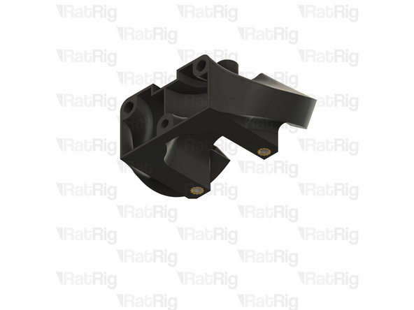
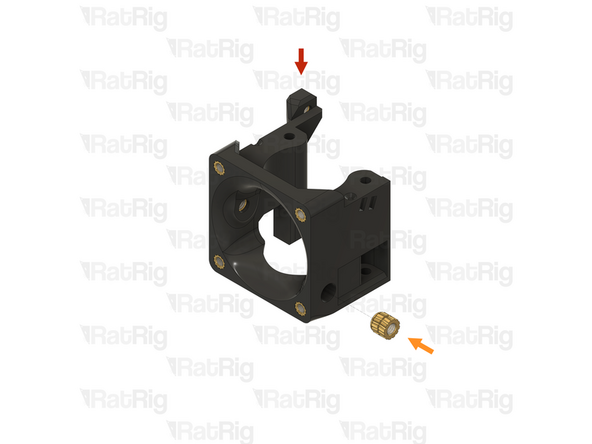
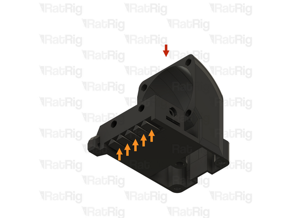
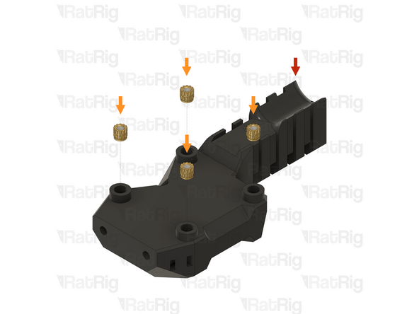
1x rr_toolhead_vc4_back
-
Built-in support material
-
The support material may not be present. If it is, remove all five pieces as shown
-
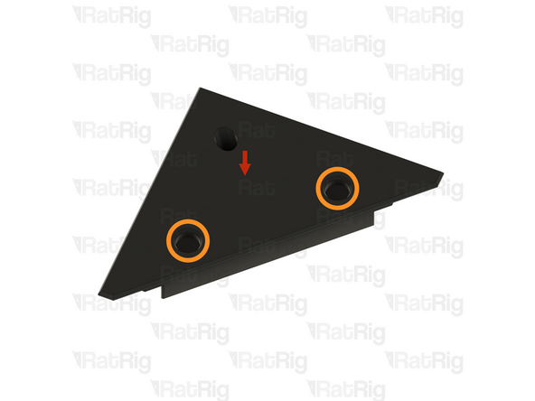
1x M3 heat insert
-
Install an M3 heat insert into the marked hole
-
Remember to change the heat insert tip in the soldering iron for the M3 sized tip
-
Allow the soldering iron to cool before changing the tips
-
-
-
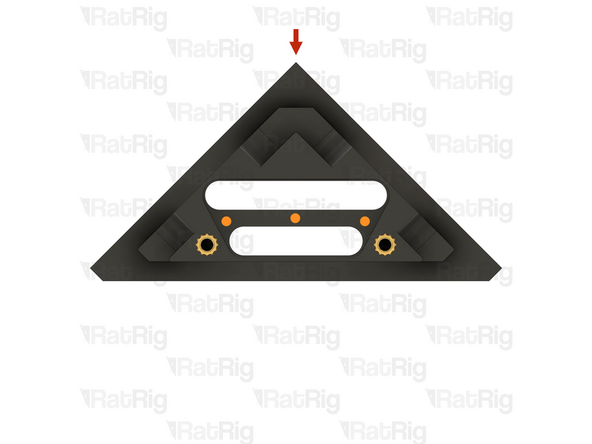
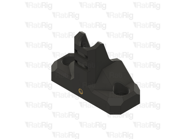
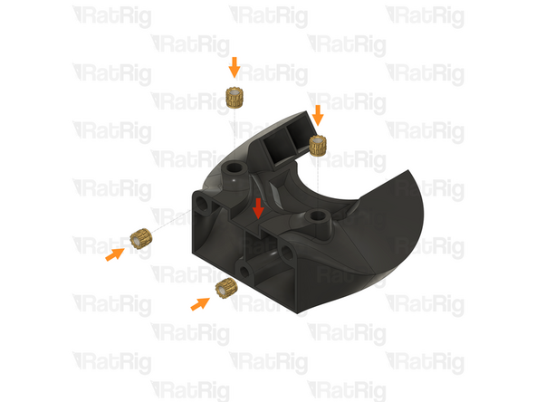
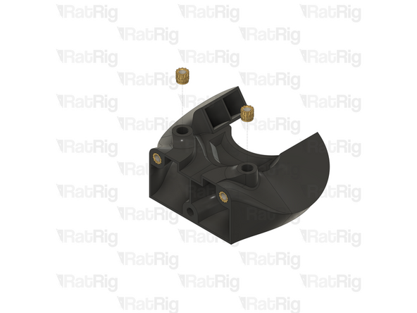
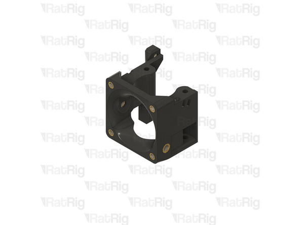
1x Back assembly from the previous step
-
7x M3 heat insert
-
Install an M3 heat insert into each of the marked holes
-
-
-
1x rr_toolhead_vc4_back_clamp
-
Clear the sacrificial layers from the marked hole
-
It is recommended to use a 3mm drill to clear the sacrificial layers
-
Prepare two of these printed parts
-
-
-
1x Toolhead back belt clamp from the previous step
-
1x M3 heat insert
-
Install an M3 heat insert into the marked hole
-
Prepare two of these printed parts
-
-
-
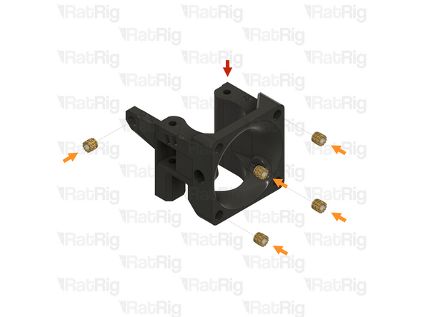
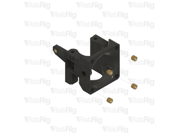
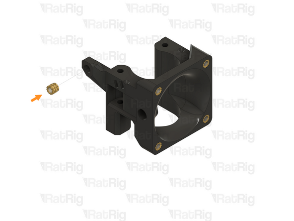
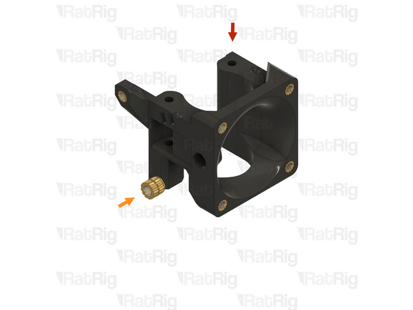
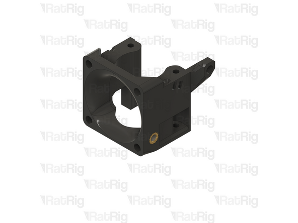
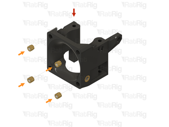
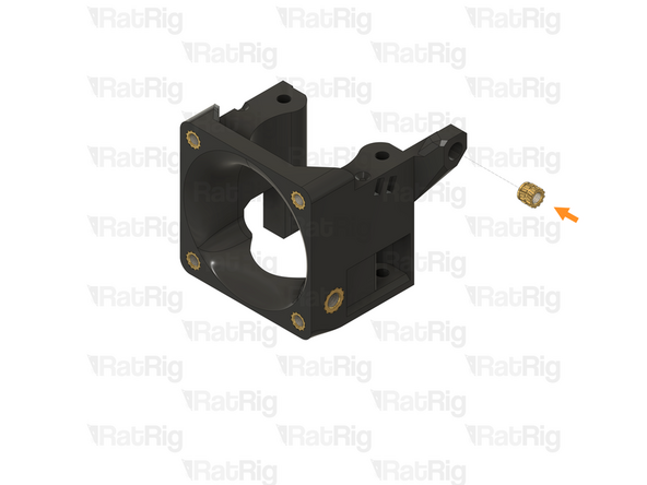
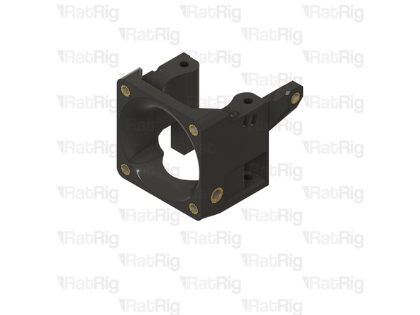
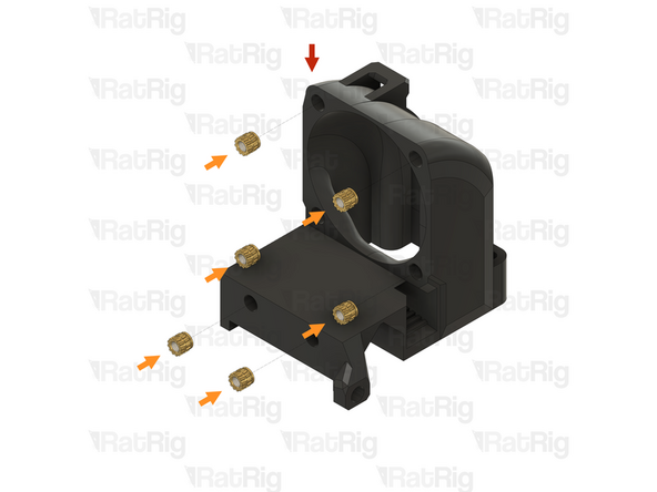
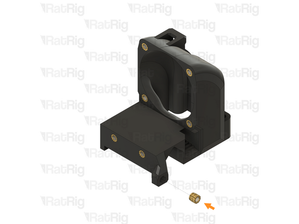
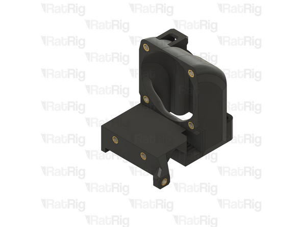
1x rr_toolhead_vc4_toolboard_vertical
-
4x M3 heat insert
-
Install an M3 heat insert into each of the marked holes
-
-
-
2x vc4_adapter_octopus (SKU: PP000301)
-
2x vc4_adapter_rpi (SKU: PP000302)
-
1x vc4_cable_guide_4 (SKU: PP000304)
-
3x vc4_cable_guide_5 (SKU: PP000305)
-
1x vc4_cable_guide_cross (SKU: PP000306)
-
4x vc4_electronics_1.2_corner (SKU: PP000352)
-
4x M2.5 heat insert (SKU: HW3776NC)
-
50x M3 heat insert (SKU: HW3224NC)
-
-
-
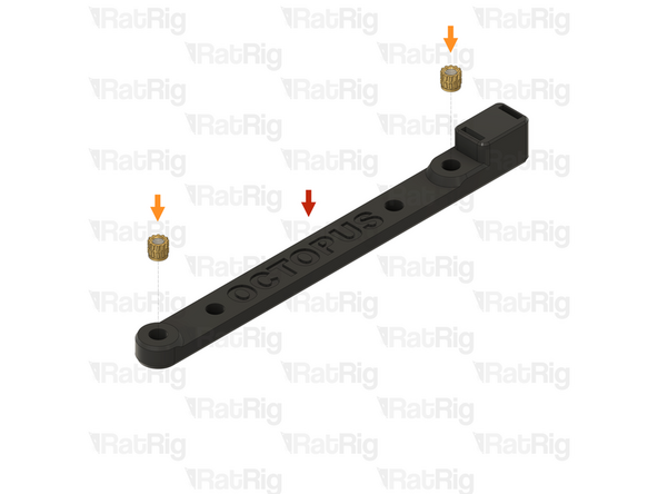
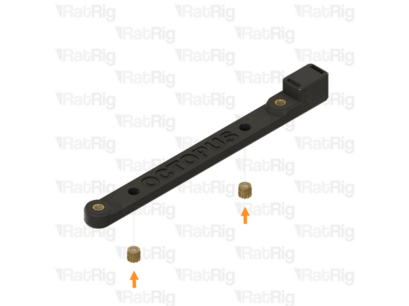
1x vc4_adapter_octopus
-
4x M3 heat insert
-
Install an M3 heat insert into each of the marked holes
-
Prepare two of these printed parts
-
-
-
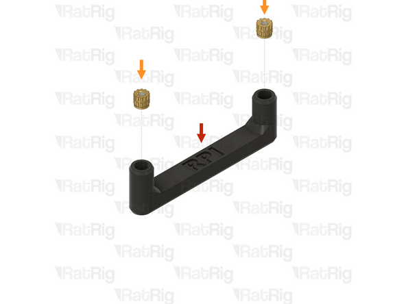
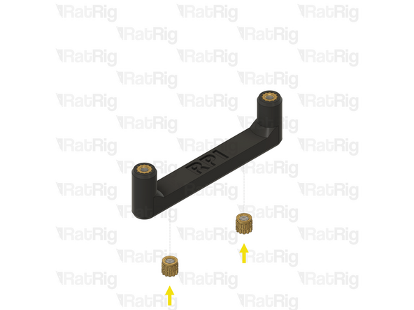
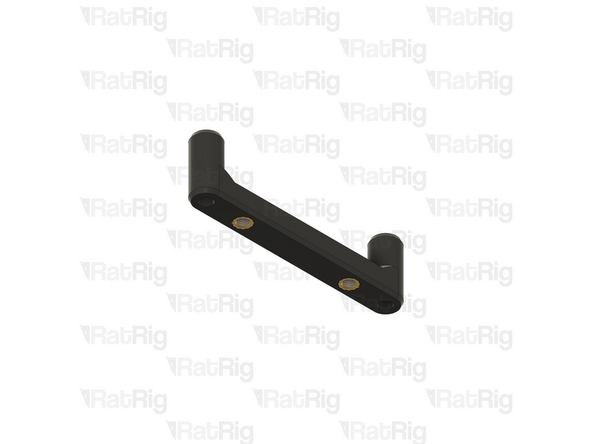
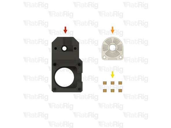
1x vc4_adapter_rpi
-
2x M2.5 heat insert
-
2x M3 heat insert
-
Install an M3 heat insert into each of the marked holes
-
Remember to change the heat insert tip in the soldering iron for the correct size when swapping between M2.5 and M3
-
Allow the soldering iron to cool before changing the tips
-
Prepare two of these printed parts
-
-
-
1x vc4_cable_guide_4
-
2x M3 heat insert
-
Install an M3 heat insert into each of the marked holes
-
-
-
1x vc4_cable_guide_5
-
2x M3 heat insert
-
Install an M3 heat insert into each of the marked holes
-
Prepare three of these printed parts
-
-
-
1x vc4_cable_guide_cross
-
2x M3 heat insert
-
Install an M3 heat insert into each of the marked holes
-
-
-
1x vc4_electronics_1.2_corner
-
3x M3 heat insert
-
Install an M3 heat insert into each of the marked holes
-
Prepare four of these printed parts
-
-
-
1x Electronics enclosure corner from the previous step
-
4x M3 heat insert
-
Install an M3 heat insert into each of the marked holes
-
Prepare four of these printed parts
-
-
-
If you are building a CoreXY variant of the V-Core 4.0, then please skip to preparing the electronics components
-
If you are building a Hybrid or IDEX variant of the V-Core 4.0, then please continue following the next steps
-
-
-
2x vc4_y_belt_clamp_body (SKU: PP000275)
-
6x M3 heat insert (SKU: HW3224NC)
-
-
-
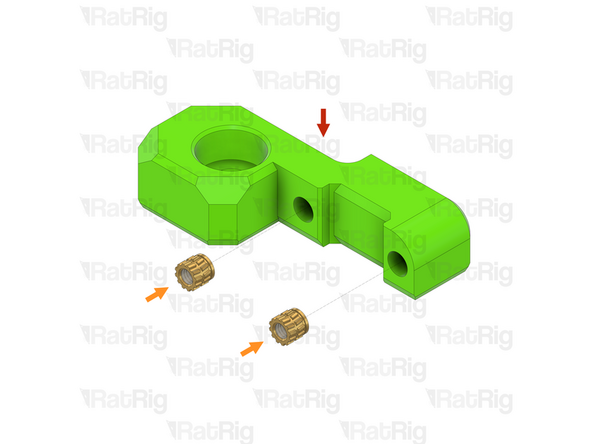
1x vc4_y_belt_clamp_body
-
3x M3 heat insert
-
Install an M3 heat insert into each of the marked holes
-
Prepare two of these printed parts
-
-
-
If you are building a CoreXY or Hybrid variant of the V-Core 4.0, then please skip to preparing the electronics components
-
If you are building an IDEX variant of the V-Core 4.0, then please continue following the next steps
-
-
-
2x rr_toolhead_vc4_shroud (SKU: PP000331)
-
1x rr_toolhead_vc4_front_idex_t0_beacon (SKU: PP000336)
-
1x rr_toolhead_vc4_front_idex_t1 (SKU: PP000317)
-
2x rr_toolhead_vc4_duct_idex (SKU: PP000313)
-
1x rr_toolhead_vc4_back_idex_t0 (SKU: PP000310)
-
1x rr_toolhead_vc4_back_idex_t1 (SKU: PP000311)
-
2x M4 heat insert (SKU: HW3791NC)
-
38x M3 heat insert (SKU: HW3224NC)
-
-
-
1x rr_toolhead_vc4_shroud
-
Clear the sacrificial layers from the four marked holes
-
It is recommended to use a 3mm drill to clear the sacrificial layers
-
Prepare two of these printed parts
-
-
-
1x rr_toolhead_vc4_duct_idex
-
2x M3 heat insert
-
Install an M3 heat insert into each of the marked holes
-
Prepare two of these printed parts
-
-
-
1x IDEX duct assembly from the previous step
-
4x M3 heat insert
-
Install an M3 heat insert into each of the marked holes
-
Prepare two of these printed parts
-
-
-
1x rr_toolhead_vc4_front_idex_t0_beacon
-
5x M3 heat insert
-
Install an M3 heat insert into each of the marked holes
-
-
-
1x T0 front assembly from the previous step
-
1x M4 heat insert
-
Install an M4 heat insert into the marked hole
-
Remember to change the heat insert tip in the soldering iron for the M4 sized tip
-
Allow the soldering iron to cool before changing the tips
-
-
-
1x rr_toolhead_vc4_front_idex_t1
-
1x M4 heat insert
-
Install an M4 heat insert into the marked hole
-
-
-
1x T1 front assembly from the previous step
-
5x M3 heat insert
-
Install an M3 heat insert into each of the marked holes
-
Remember to change the heat insert tip in the soldering iron for the M3 sized tip
-
Allow the soldering iron to cool before changing the tips
-
-
-
1x rr_toolhead_vc4_back_idex_t0
-
Built-in support material
-
The support material may not be present. If it is, remove all six pieces as shown
-
1x M3 heat insert
-
Install an M3 heat insert into each of the marked holes
-
-
-
1x T0 back assembly from the previous step
-
7x M3 heat insert
-
Install an M3 heat insert into each of the marked holes
-
-
-
1x rr_toolhead_vc4_back_idex_t1
-
Built-in support material
-
The support material may not be present. If it is, remove all six pieces as shown
-
1x M3 heat insert
-
Install an M3 heat insert into each of the marked holes
-
-
-
1x T1 back assembly from the previous step
-
7x M3 heat insert
-
Install an M3 heat insert into each of the marked holes
-
-
-
2x rr_toolhead_vc4_toolboard_vertical (SKU: PP000325)
-
2x rr_toolhead_vc4_back_clamp (SKU: PP000309)
-
10x M3 heat insert (SKU: HW3224NC)
-
-
-
1x rr_toolhead_vc4_back_clamp
-
Clear the sacrificial layers from the marked hole
-
It is recommended to use a 3mm drill to clear the sacrificial layers
-
Prepare two of these printed parts
-
-
-
1x Toolhead back belt clamp from the previous step
-
1x M3 heat insert
-
Install an M3 heat insert into the marked hole
-
Prepare two of these printed parts
-
-
-
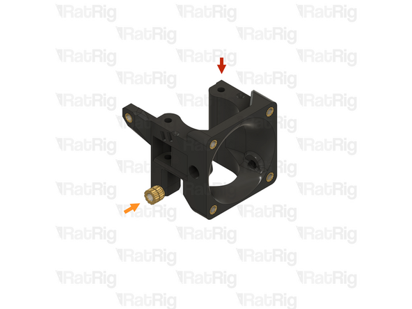
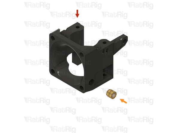
1x rr_toolhead_vc4_toolboard_vertical
-
4x M3 heat insert
-
Install an M3 heat insert into each of the marked holes
-
Prepare two of these printed parts
-
-
-
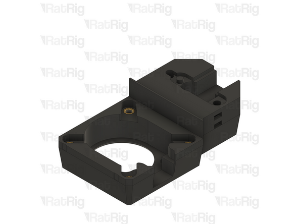
1x vc4_vaoc_body (SKU: PP000355)
-
1x vc4_vaoc_diffusor (SKU: PP000358)
-
6x M3 heat insert (SKU: HW3224NC)
-
-
-
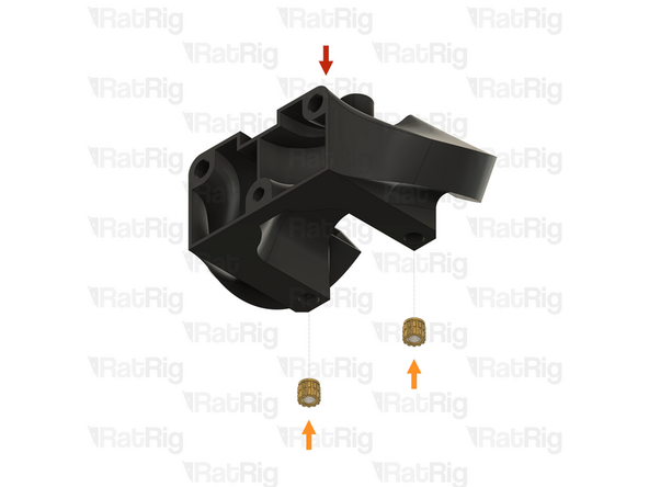
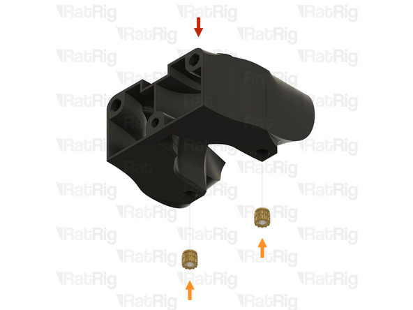
1x vc4_vaoc_body
-
Clear the sacrificial layers from the two marked holes
-
The sacrificial layers may not be present. If they are, it is recommended to use a 3mm drill to clear them
-
-
-
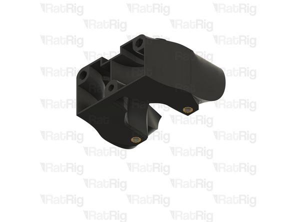
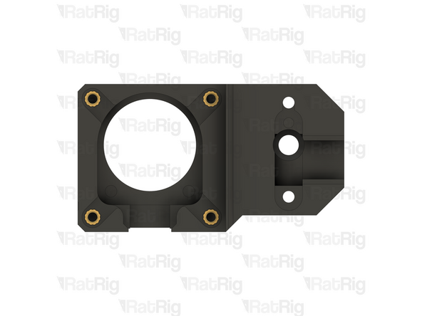
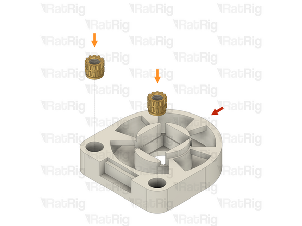
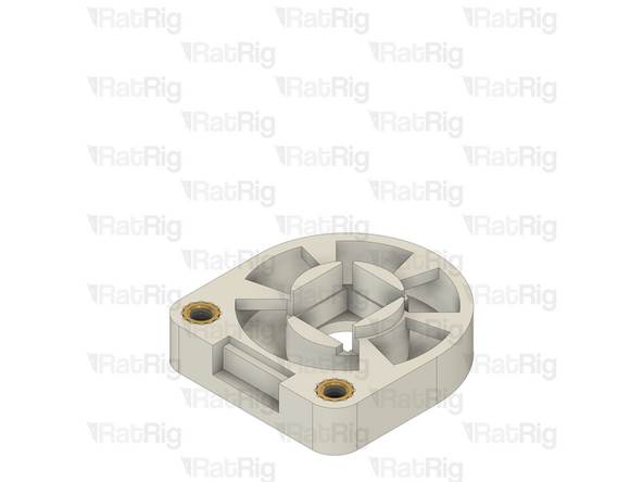
1x VAOC body from the previous step
-
4x M3 heat insert
-
Install an M3 heat insert into each of the marked holes
-
-
-
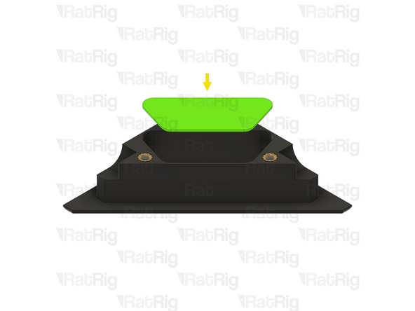
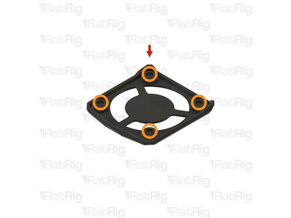
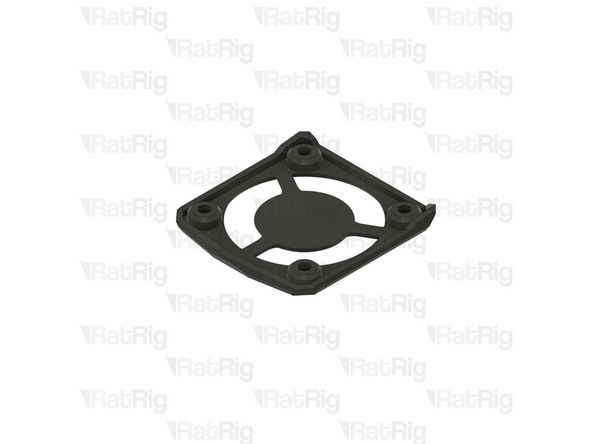
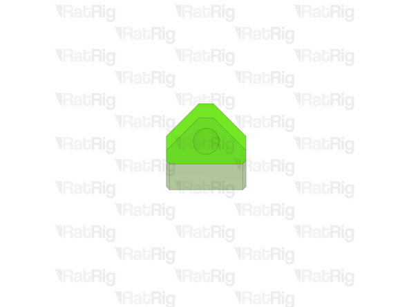
1x vc4_vaoc_diffusor
-
2x M3 heat insert
-
Install an M3 heat insert into each of the marked holes
-
-
-
Some of the electronics components require preparation at this stage to make later assembly more straightforward
-
Crimping terminals to the wiring and installing the connectors is a delicate and time-consuming process
-
It is recommended to take a brief break before continuing, and to take your time when following the next steps
-
If you have never crimped JST or Molex terminals before, consider watching tutorials (e.g., on YouTube) to help you get it right
-
The following steps will guide you through preparing these electronics components and wiring
-
-
-
The following tools are required for this section of the guide:
-
Wire cutters
-
Wire strippers
-
A tape measure, or ruler
-
Crimping tools for the following terminals:
-
JST-XH, JST-PH & Dupont
-
Molex Micro-Fit
-
18-14 AWG Fork
-
-
-
1x Phaetus Rapido 2.0 Plus UHF Hotend (SKU: HW3450EC)
-
Please note: Make sure that the Rapido has the UHF adapter and UHF silicone sock installed. The V-Core 4 is not compatible with the Rapido in the HF configuration
-
1x Connector - 2 Pin - JST XHP-2 - 2.54 Male (SKU: HW3902EC)
-
2x Crimp - JST XH 2.54 (SKU: HW3910EC)
-
-
-
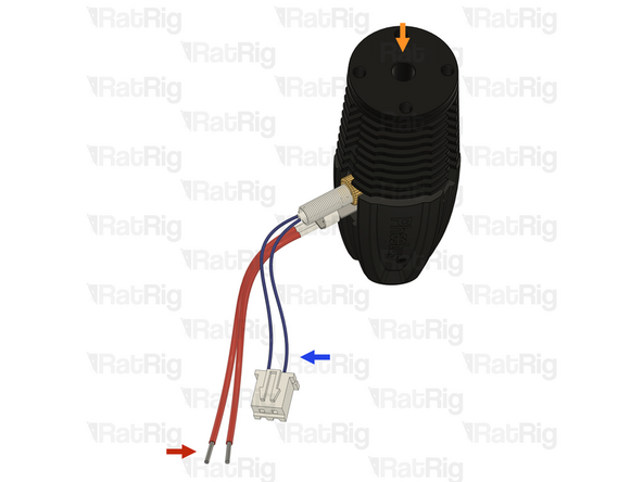
Please note: The wire colours shown in the image are for illustration purposes only
-
Phaetus Rapido 2.0 Plus UHF Hotend
-
Hotend Heater - Lower wires - Shown in red: Cut the wires to a length of 150mm and strip 5mm of the insulation, leaving the inner wire bare
-
Thermistor - Upper wires - Shown in blue: Cut the wires to a length of 160mm strip 2mm of the insulation from each
-
Crimp a JST-XH terminal onto the end of each of the stripped thermistor wires
-
Insert the crimped terminals into the JST-XH-2 connector. The positions do not matter. The thermistor is thermally sensitive resistor which does not have a specific polarity. The crimp terminals will "click" when fully inserted
-
Please note: If you are building an IDEX variant of the V-Core 4.0, repeat both the previous step, and this step, to prepare a second hotend assembly
-
-
-
1x Cable 120mm - 3 Conductor 24AWG - JST XH2.54 male to Bare wire (SKU: HW3906EC)
-
1x Connector - 5 Pin - JST-PH
-
3x Crimp - JST-PH
-
The 5 pin JST-PH connector and JST-PH crimp terminals are included with the BIGTREETECH EBB42 USB/CAN Toolboard (SKU: HW3334EC)
-
-
-
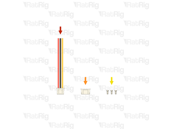
1x Cable 120mm - 3 Conductor 24AWG - JST XH2.54 male to Bare wire
-
Strip 2mm of the insulation from the end of each of the bare wires
-
Crimp a JST-PH terminal onto each of the three stripped wires
-
The JST-PH crimp terminals are very small, and not the easiest to crimp. Take your time
-
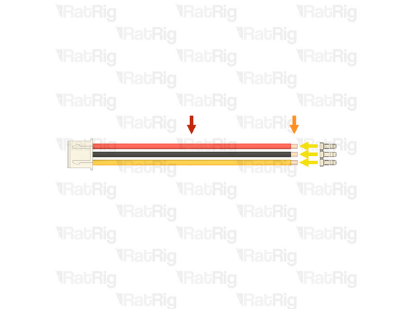
Connector - 5 Pin - JST PH
-
Install the crimped terminal into the connector housing, into the positions shown. The crimp terminal will "click" when fully inserted
-
Wiring the endstop incorrectly will lead to damage of the endstop, or the toolboard. Double check the connections before proceeding
-
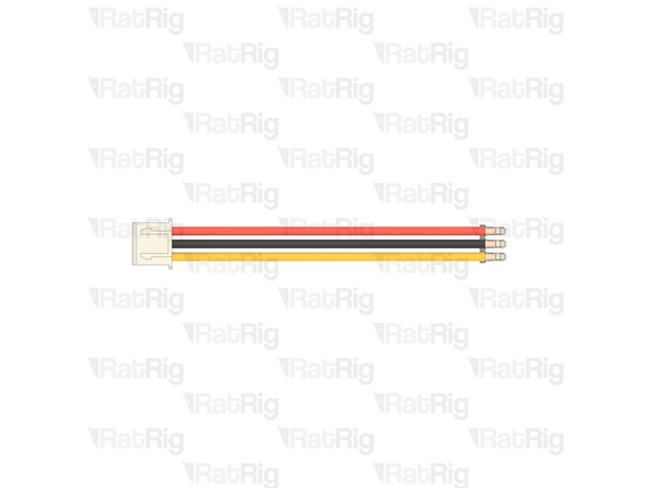
Please note: If you are building an IDEX variant of the V-Core 4.0, repeat both the previous step, and this step, to prepare a second toolhead endstop cable
-
-
-
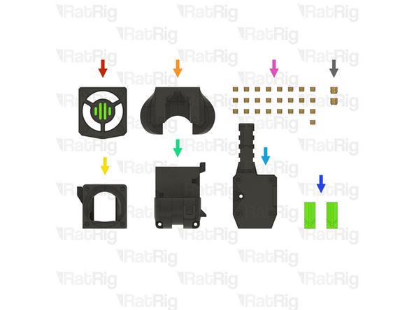
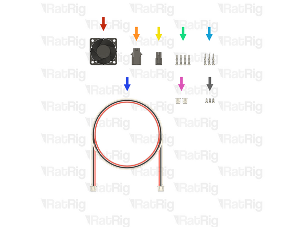
1x Fan - 4028 Axial - Sanyo Denki (SKU: HW2962EC)
-
1x Connector - Molex Micro-Fit - 4 Pin - Female (43020-0400) (SKU: HW3903EC)
-
1x Connector - Molex Micro-Fit - 4 Pin - Male (43025-0400) (SKU: HW3904EC)
-
4x Crimp - Molex Micro-Fit (43025 compatible) (SKU: HW3930EC)
-
3x Crimp - Molex Micro-Fit (43020 compatible) (SKU: HW3909EC)
-
1x Cable 1500mm - 3 Conductor 24AWG - JST XH2.54 to JST XH2.54 (Endstop pin out) (SKU: HW3029EC)
-
2x Connector - 2 Pin - JST XHP-2 - 2.54 Male (SKU: HW3902EC)
-
4x Crimp - JST XH 2.54 (SKU: HW3910EC)
-
-
-
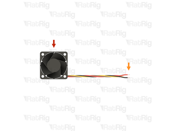
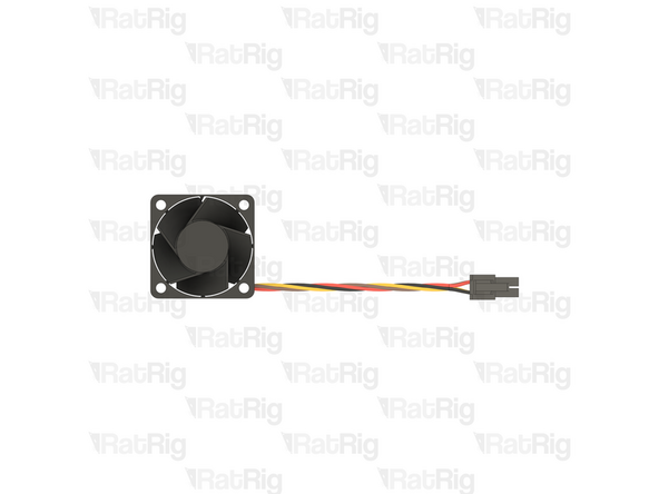
Fan - 4028 Axial - Sanyo Denki
-
Strip 3mm of the insulation from the end of each of the bare wires
-
If the wires are already stripped, it is recommended to cut the stripped ends off and then strip the insulation by the correct length
-
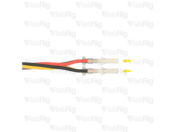
Molex Micro-Fit (43025 compatible)
-
Please note: There are two types of Molex crimp terminals provided, male (with a pin), and female (with a hole). The ones required for this step are female
-
Crimp a Molex Micro-Fit (43025 compatible) terminal onto each of the four stripped wires
-
Before proceeding, verify that all four crimp terminals are correctly crimped to the wires, the terminals are very difficult to remove from the housing once installed
-
-
-
Connector - Molex Micro-Fit - 4 Pin - Male (43025-0400)
-
Please note: Make sure to use the correct Molex Micro-Fit connector, and make sure it is oriented as shown (with the locking tab at the top)
-
Insert the crimped terminals into the Molex Micro-Fit connector, in the positions shown. The crimp terminals will "click" when fully inserted
-
Make sure the wires are inserted into the correct positions. Incorrect wiring will damage the fan and electronics
-
Top left - 12V - Red Wire
-
Top right - Ground - Black Wire
-
Bottom left - PWM - Brown Wire - (Blue if the fan is from NIDEC)
-
Bottom right - Tachometer - Yellow Wire - (White if the fan is from NIDEC)
-
-
-
Cable 1500mm - 3 Conductor 24AWG - JST XH2.54 to JST XH2.54 (Endstop pin out)
-
Use wire cutters to cut off the JST-XH connector from one end of the cable, leaving three bare wires
-
The connector can be discarded, it is no longer needed
-
Strip 3mm of the insulation from the end of each of the bare wires
-
-
-
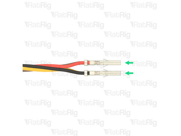
Prepared wires from the previous step
-
Crimp - Molex Micro-Fit (43020 compatible)
-
Please note: There are two types of Molex crimp terminals provided, male (with a pin), and female (with a hole). The ones required for this step are male
-
Crimp a Molex Micro-Fit (43020 compatible) terminal onto each of the three stripped wires
-
Before proceeding, verify that all three crimp terminals are correctly crimped to the wires, the terminals are very difficult to remove from the housing once installed
-
-
-
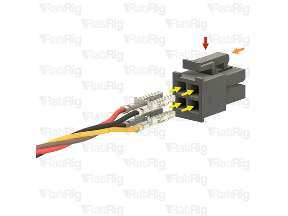
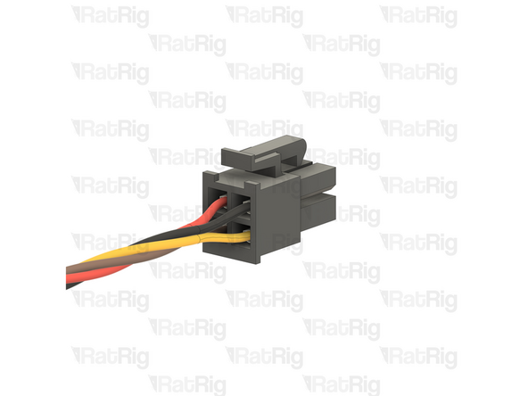
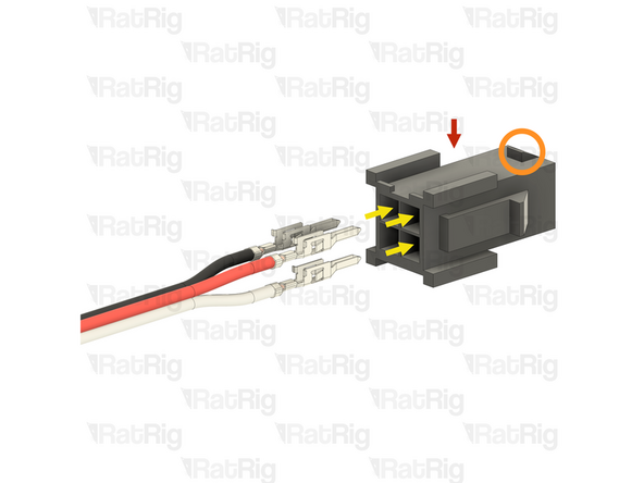
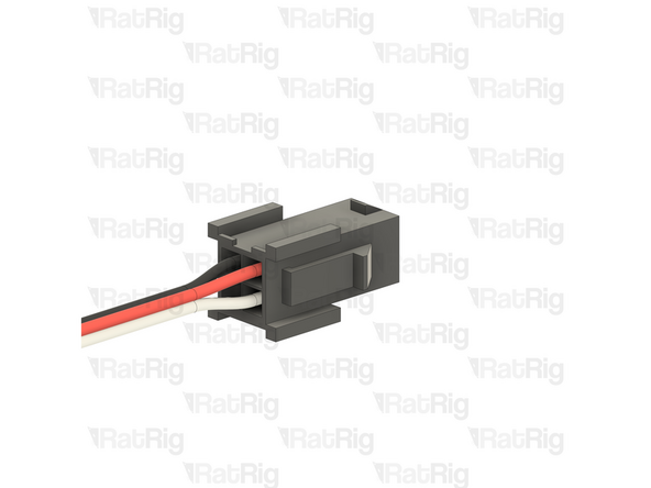
Connector - Molex Micro-Fit - 4 Pin - Female (43020-0400)
-
Please note: Make sure to use the correct Molex Micro-Fit connector, and make sure it is oriented as shown (with the hooked tab at the top)
-
Insert the crimped terminals into the Molex Micro-Fit connector, in the positions shown. The crimp terminals will "click" when fully inserted
-
Make sure the wires are inserted into the correct positions. Incorrect wiring will damage the fan and electronics
-
Top left - Ground - Black Wire
-
Top right - 12V - Red Wire
-
Bottom right - PWM - White Wire
-
-
-
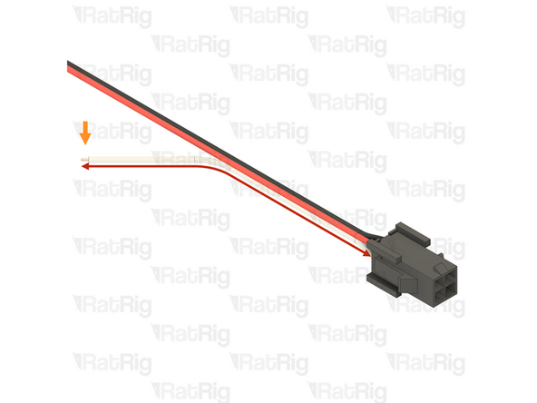
Measure 70mm from the newly installed Molex Micro-Fit connector and cut the White Wire
-
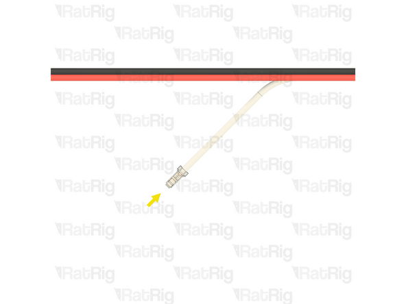
Strip 2mm of the insulation from the end of the wire
-
Crimp - JST XH 2.54
-
Crimp a JST-XH terminal onto the end of the stripped wire
-
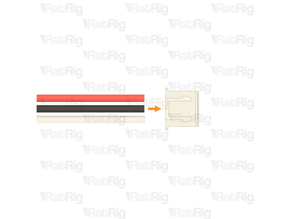
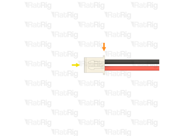
Connector - 2 Pin - JST XHP-2
-
Install the crimped terminal into the right side of the connector housing, as shown. The crimp terminal will "click" when fully inserted
-
The left side terminal on the connector will remain empty
-
-
-
Please note: It is possible to "de-pin" the existing JST-XH-3 connector, saving the need to crimp new terminals on to the wires, but that will not be covered in this guide
-
Opposite end of the cable assembly from the previous steps
-
Use wire cutters to cut off the JST-XH connector from the other end of the cable, leaving three bare wires
-
The connector, and the remaining white wire can be discarded, they are no longer needed
-
Strip 2mm of the insulation from the end of each of the remaining two bare wires
-
-
-
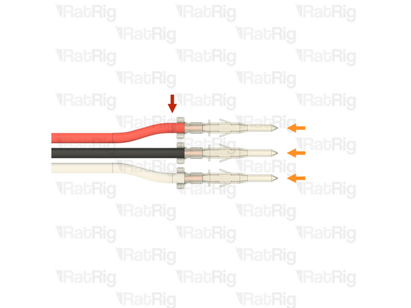
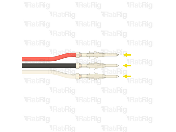
Crimp a JST-XH terminal onto the end of each stripped wire
-
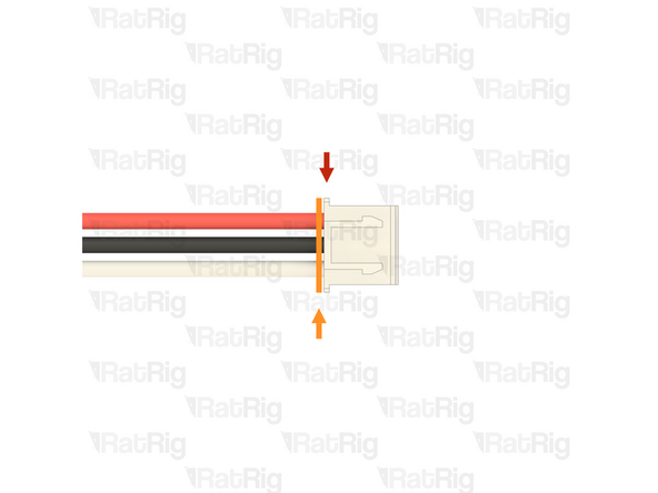
Connector - 2 Pin - JST XHP-2
-
Insert the crimped terminals into the JST-XH-2 connector in the positions shown. The crimp terminals will "click" when fully inserted
-
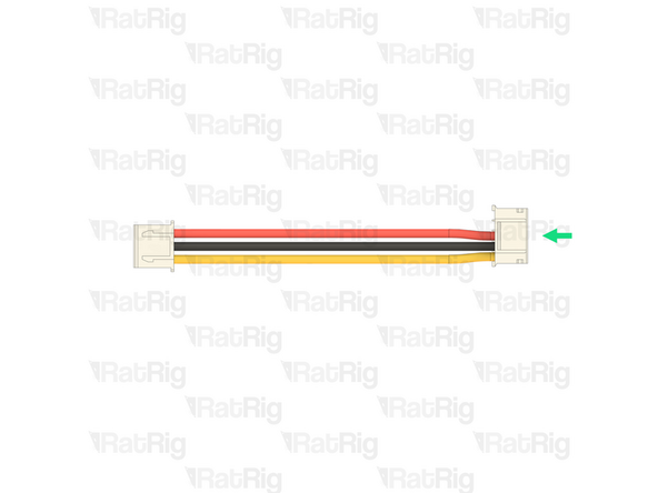
Make sure the wires are inserted into the correct positions. Incorrect wiring will damage the fan and electronics
-
Left - 12V - Red Wire
-
Right - Ground - Black Wire
-
Before proceeding, verify that your cable assembly matches the one shown in the image
-
Please note: If you are building an IDEX variant of the V-Core 4.0, repeat all steps beginning at step 68, to prepare a second 4028 fan and extension cable
-
-
-
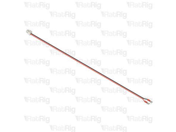
1500mm - Wire - DC Power - 18AWG RED (SKU: HW3901EC)
-
1500mm - Wire - DC Power - 18AWG BLACK (SKU: HW3900EC)
-
The following two parts are included in the BIGTREETECH EBB42 USB/CAN Toolboard box (SKU: HW3334EC)
-
1x Connector - Molex Micro-Fit - 4 Pin - Male - White
-
2x Crimp - Molex Micro-Fit (43025 compatible)
-
2x Fork Terminal - 3.7mm Insulated (16-22 AWG) (SKU: HW3835EC)
-
-
-
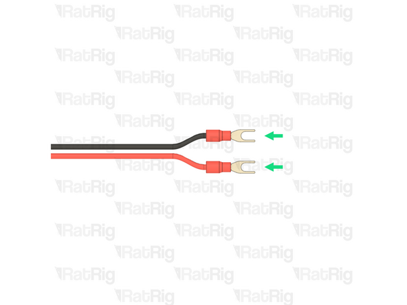
1500mm - Wire - DC Power - 18AWG BLACK
-
1500mm - Wire - DC Power - 18AWG RED
-
Strip 3mm of the insulation from one end of each of the bare wires
-
Molex Micro-Fit (43025 compatible)
-
Crimp a Molex Micro-Fit (43025 compatible) terminal onto each of the stripped wires
-
Before proceeding, verify that both crimp terminals are correctly crimped to the wires, the terminals are very difficult to remove from the housing once installed
-
-
-
Connector - Molex Micro-Fit - 4 Pin - Male - White
-
Please note: Make sure the Molex Micro-Fit connector is oriented as shown (with the locking tab at the top)
-
Insert the crimped terminals into the Molex Micro-Fit connector, in the positions shown. The crimp terminals will "click" when fully inserted
-
Make sure the wires are inserted into the correct positions. Incorrect wiring will damage the fan and electronics
-
Top left - Empty
-
Top right - Empty
-
Bottom left - 24V - Red Wire
-
Bottom right - Ground - Black Wire
-
-
-
Opposite end of the cable prepared in the previous steps
-
Please note: The wires provided are 1500mm long which is sufficient for a V-Core 4 500. It is possible, though not necessary, to shorten these wires for smaller size builds to assist in cable management
-
V-Core 4 300: 1100mm is sufficient
-
V-Core 4 400: 1300mm is sufficient
-
Strip 5mm of the insulation from the end of each of the bare wires
-
2x Fork Terminal - 3.7mm Insulated (16-22 AWG)
-
Crimp a Fork terminal onto each of the two stripped wires
-
Please note: If you are building an IDEX variant of the V-Core 4.0, repeat all steps beginning at step 77, to prepare a second toolhead power cable
-
-
-
The following part is included in the Orbiter 2 smart sensor box (SKU: HW3990EC)
-
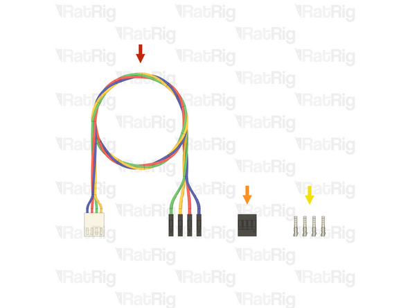
1x Orbiter 2 Smart Sensor Wiring Harness
-
1x Connector - 4 Pin - Dupont Housing 4x1 - 2.54mm (SKU: HW4160EC )
-
4x Crimp - Dupont 2.54mm Female (SKU: HW4161EC)
-
-
-
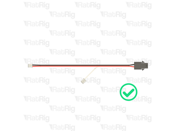
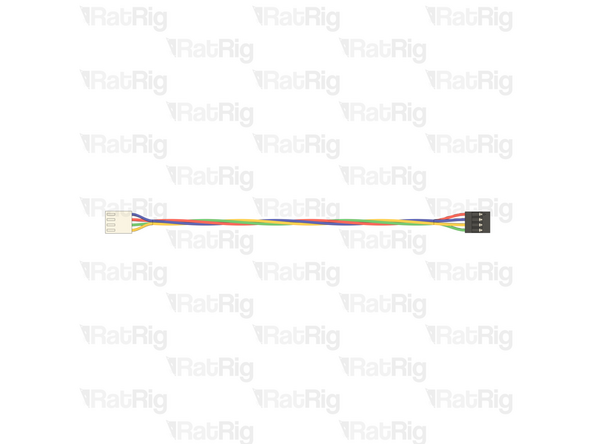
Orbiter 2 Smart Sensor Wiring Harness
-
Measure 160mm from the back of the single white connector
-
Use wire cutters to cut the wiring harness the measured length
-
The remaining wire can be discarded, it is no longer needed
-
Strip 2mm of the insulation from the end of each of the bare wires
-
-
-
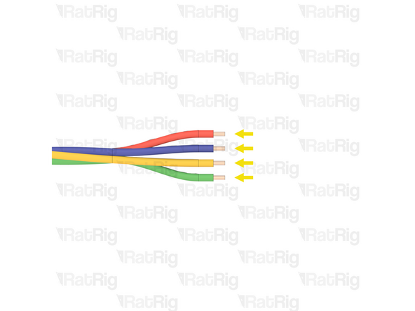
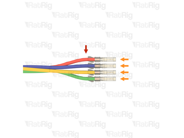
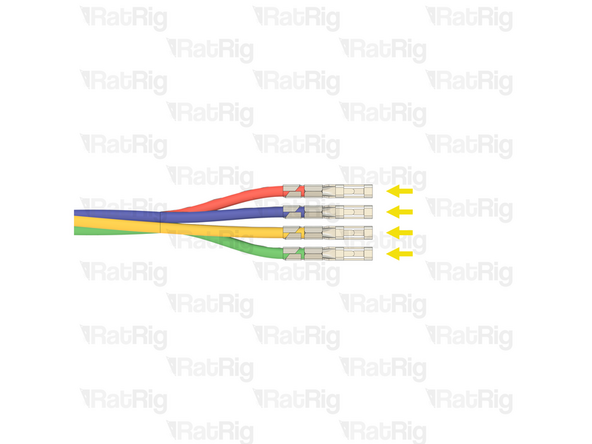
Prepared wires from the previous step
-
Crimp - Dupont 2.54mm Female
-
Crimp a female Dupont terminal onto each of the four stripped wires
-
Before proceeding, verify that all four crimp terminals are correctly crimped to the wires
-
-
-
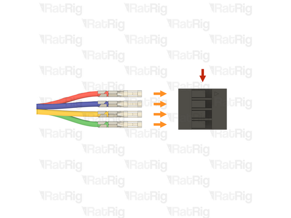
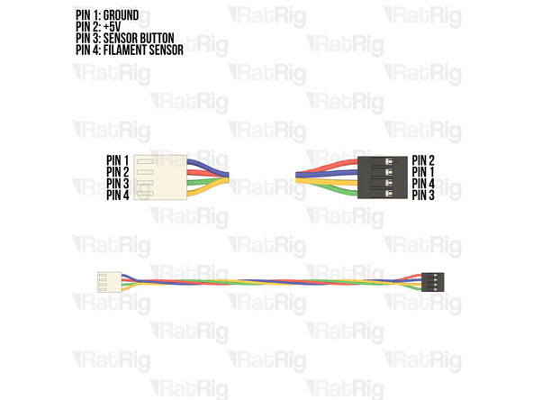
Connector - 4 Pin - Dupont Housing 4x1 - 2.54mm
-
Please note: The wiring colour shown may not match your Orbiter smart sensor harness. It is very important to use the provided wiring diagram to correctly assemble the cable. Do not blindly follow the wire colours
-
Make sure the wires are inserted into the correct positions. Incorrect wiring will damage the Orbiter smart sensor, toolboard, and other electronics
-
Insert the crimped terminals into the Dupont connector, using the wiring diagram provided. The crimp terminals will "click" when fully inserted
-
Please note: If you are building an IDEX variant of the V-Core 4.0, repeat all steps beginning at step 81, to prepare a second 4028 fan and extension cable
-
-
-
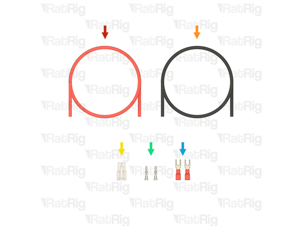
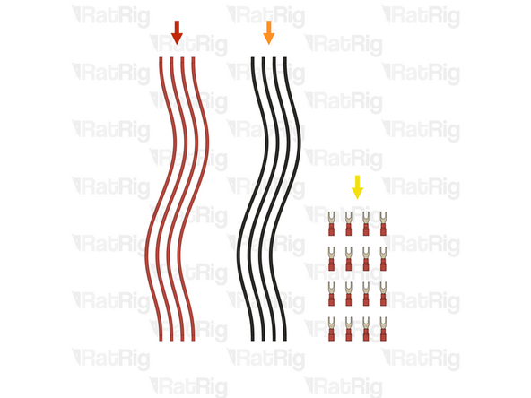
4x Wire - DC - 16AWG - Red - 270mm (SKU: HW2889EC)
-
4x Wire - DC - 16AWG - Black - 270mm (SKU: HW2888EC)
-
16x Fork terminal - 3.7mm insulated (16-22AWG) (SKU: HW3835EC)
-
-
-
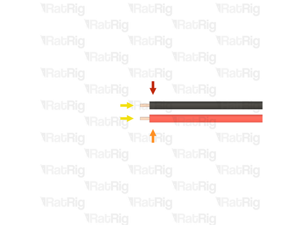
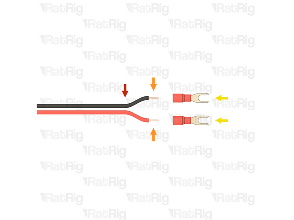
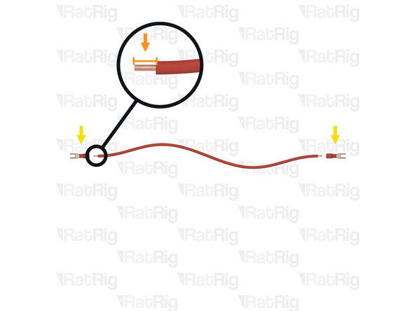
1x Wire - DC - 16AWG - Red - 270mm
-
Strip 5mm of the insulation from the end of each of the eight bare wires
-
2x Fork Terminal - 3.7mm Insulated (16-22 AWG)
-
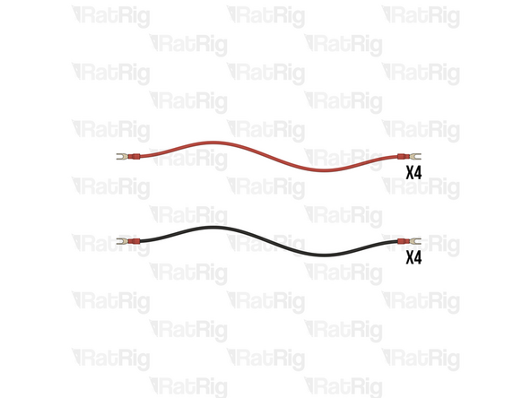
Install, and crimp, a fork terminal to each end of the wire as shown
-
Gently pull the wire to make sure it is correctly crimped. The fork terminals should be securely attached
-
Prepare four red (positive) wires and four black (negative) wires
-
-
-
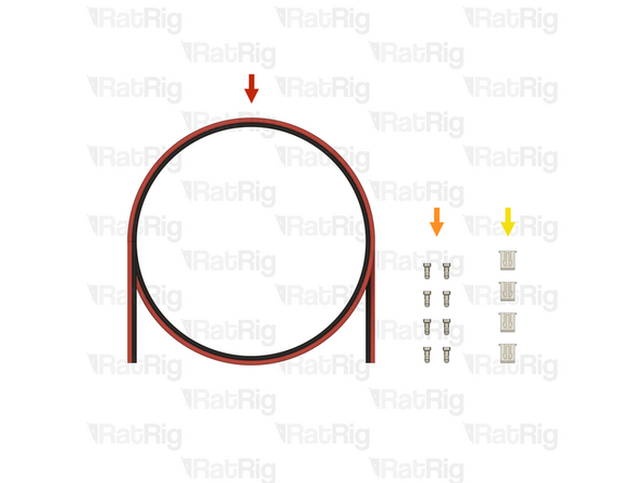
2.6m Wire - DC Power - 2 Conductor - 22 AWG (0.35mm2) - RED / BLACK - 1000mm (SKU: HW4307EC)
-
8x Crimp - JST XH 2.54 (SKU: HW3910EC)
-
4x Connector - 2 Pin - JST XHP-2 - 2.54 Male (SKU: HW3902EC)
-
-
-
Wire - DC Power - 2 Conductor - 22 AWG (0.35mm2) - RED / BLACK
-
Cut a length of the wire depending on the size of V-Core 4.0:
-
V-Core 4.0 300: 900mm
-
V-Core 4.0 400: 1100mm
-
V-Core 4.0 500: 1300mm
-
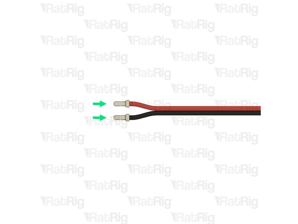
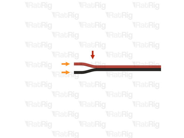
Gently separate roughly 10mm of the two conductors by gripping each and pulling them apart as shown. Repeat for the other end of the wire
-
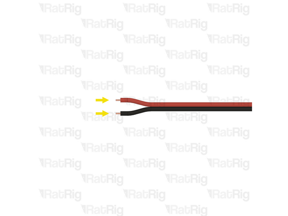
Strip 2mm of the insulation from both conductors on each end of the wire
-
Install, and crimp, a JST-XH terminal onto each of the four stripped ends
-
-
-
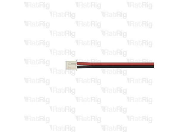
LED-to-LED cable assembly from the previous step
-
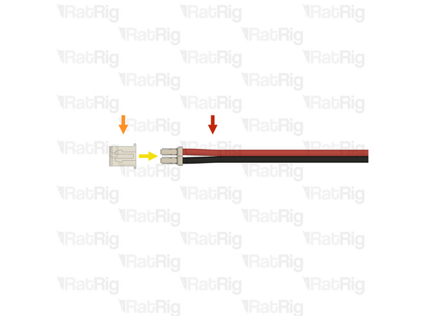
Connector - 2 Pin - JST XHP-2
-
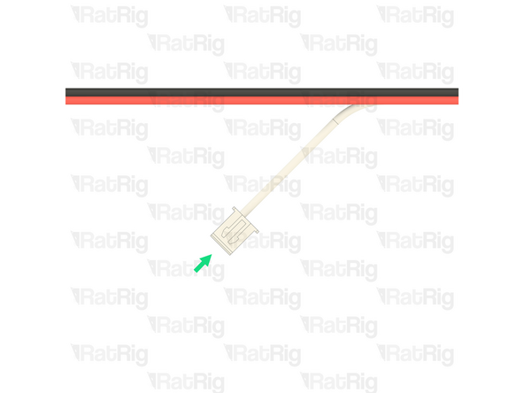
Orient the JST-XH-2 connector so that the "key" is facing upwards
-
Insert the crimped terminal on the black wire into the left position of the JST-XH-2 connector. The crimp terminals will "click" when fully inserted
-
Insert the crimped terminal on the red wire into the right position of the JST-XH-2 connector. The crimp terminals will "click" when fully inserted
-
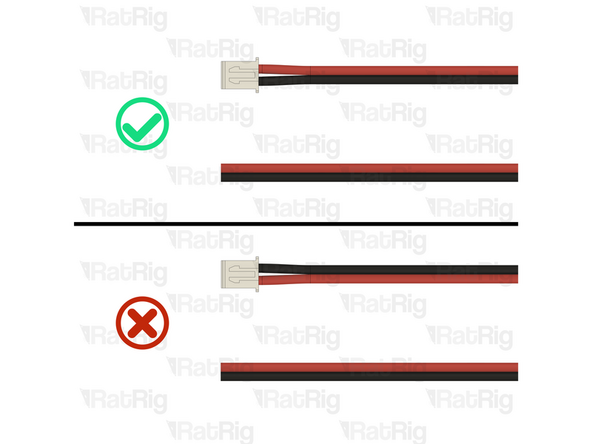
Repeat the process to install the JST-XH-2 connector on the other end of the cable. The wire positions are the same
-
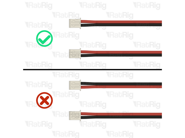
Before continuing, verify that both ends of the cable are correctly wired using the image provided. Failure to do so will cause irreparable damage to components
-
-
-
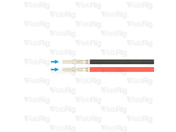
Wire - DC Power - 2 Conductor - 22 AWG (0.35mm2) - RED / BLACK
-
Cut the remaining wire to a length of 1300mm
-
Gently separate roughly 10mm of the two conductors by gripping each and pulling them apart as shown. Leave the other end unseparated for now.
-
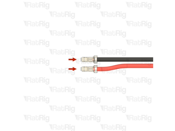
Strip 2mm of the insulation from both conductors on one end of the wire
-
Install, and crimp, a JST-XH terminal onto each of the two stripped ends
-
-
-
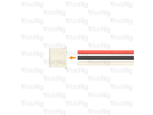
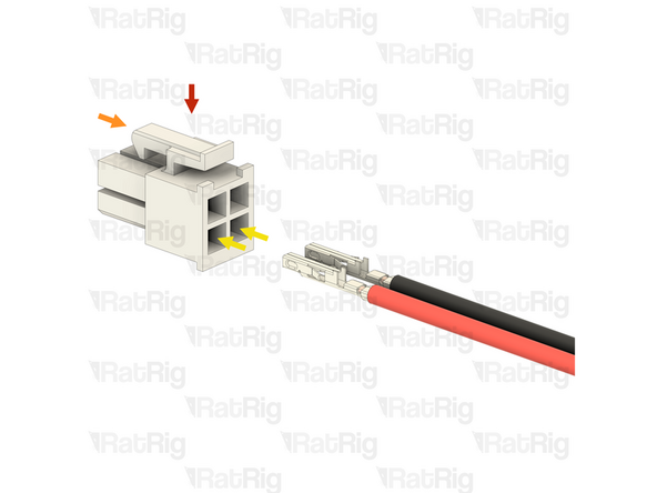
LED-to-Octopus cable assembly from the previous step
-
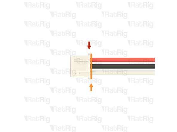
Connector - 2 Pin - JST XHP-2
-
Orient the JST-XH-2 connector so that the "key" is facing upwards
-
Insert the crimped terminal on the black wire into the left position of the JST-XH-2 connector. The crimp terminals will "click" when fully inserted
-
Insert the crimped terminal on the red wire into the right position of the JST-XH-2 connector. The crimp terminals will "click" when fully inserted
-
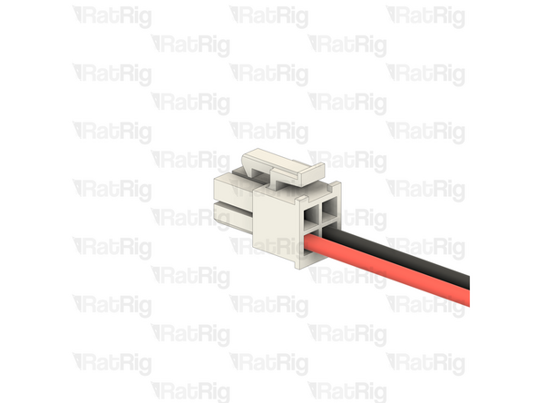
Before continuing, verify that the end of the cable is correctly wired using the image provided. Failure to do so will cause irreparable damage to components
-
-
-
All of the printed parts, and all of the non-AC related wiring, is now prepared, and will be used throughout the remainder of the assembly guide
-
Continue to the next guide: 01. Frame Assembly
-


Cancel: I did not complete this guide.
2 other people completed this guide.