Steps
21
- 01. Rat Rig Mill wiring 21 steps

In Progress
This guide is currently being written. Reload periodically to see the latest changes.

Private
This guide will not appear in search results and can only be viewed by team members!
Quiz
0
-
-
This procedure can be found on the OpenBuilds Documentation, for further information click here.
-
Follow this step if you don't have access to a multimeter. If you already identified all coil pairs in the previous step, please proceed to step 9.
-
If the two wires you joined together belong to the same coil, the shaft will become significantly harder to turn by hand.
-
If that shaft still spins easily, you have not identified a coil yet, and you must try a different combination of wires.
-
If you join together two wires that do result in the motor presenting resistance against turning, you can label these two wires as belonging to the same coil.
-
-
-
This procedure can be found on the OpenBuilds Documentation, for further information click here.
-
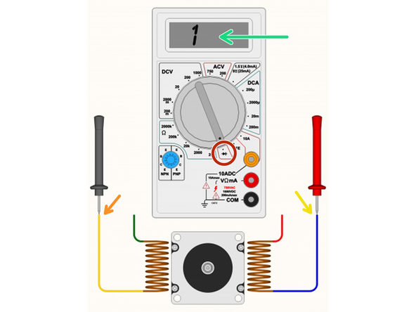
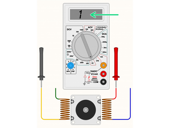
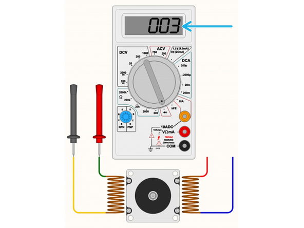
Follow this step if you have access to a multimeter, otherwise skip to Step 8.
-
Set your multimeter to Continuity / Diode Test mode.
-
Start with any random wire, and touch that to the Black/Negative probe on your multimeter.
-
Select any remaining wire and touch it with the Red/Positive probe of your multimeter:
-
If the multimeter shows [1 or 0L] it means “no connection” - indicating we did not find a coil between these two wires. Some multimeters also “beep” when it does find a connection, so if there is no beep noise, it also could indicate the coil is not between these two wires.
-
If you see a reading on the multimeter. The actual number does not matter too much, it's more important that it has some low value reading, and that the multimeter no longer displays [1] on the display. Some multimeters may “beep” when you have continuity between the wires (circuit completed by the coil in between).
-
Segment off these two wires and label them as belonging to a coil. It's important to not lose track of the coil pairs.
-
-
-
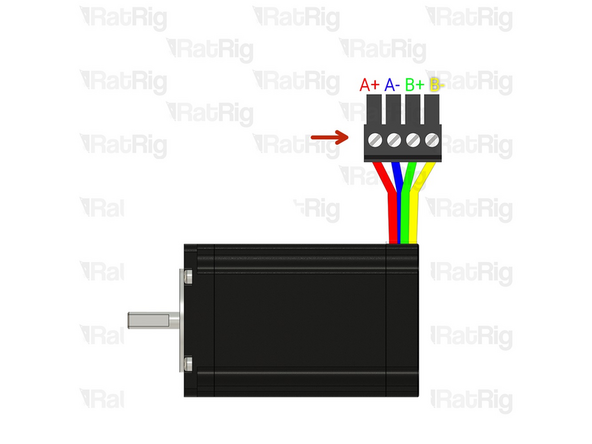
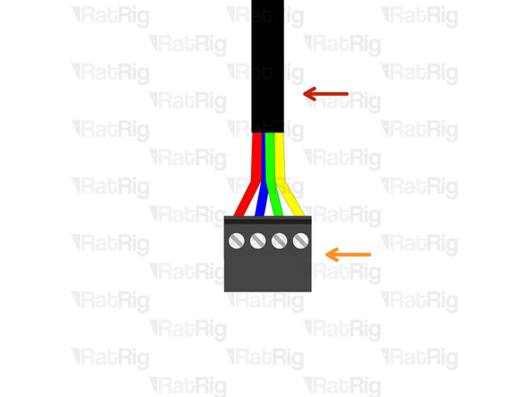
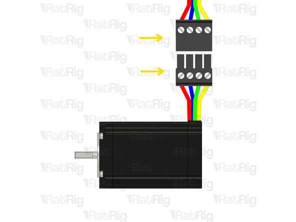
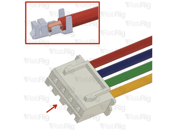
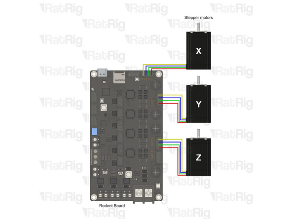
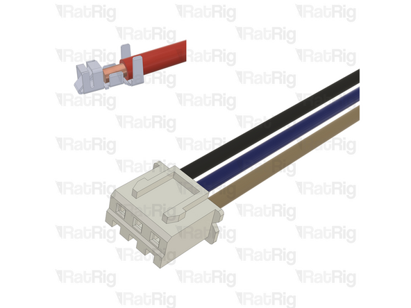
Xtension Connector - 4 Pin
-
Insert an Xtension connector (male) onto the stepper wires. The previously identified coil pairs must be next to each other. They are now designated as A pair and B pair. The + and - don't really matter at this point as long as the coil ends are together.
-
Your stepper wire colours might be different, please proceed with the correct coil pairs for your set-up.
-
Repeat the coil identification step and this step for the remaining stepper motors.
-
-
-
Prepare the 4 wire cable for the Z stepper motor.
-
4 Wire cable
-
Insert an Xtension (female) connector on to the cable end.
-
Connect the extension to the stepper motor.
-
Make sure to follow the wire colour scheme to preserve the motor coil pairs.
-
Should the integrity of the motor coil pairs not be maintained, the motor will experience impaired operational functionality.
-
-
-
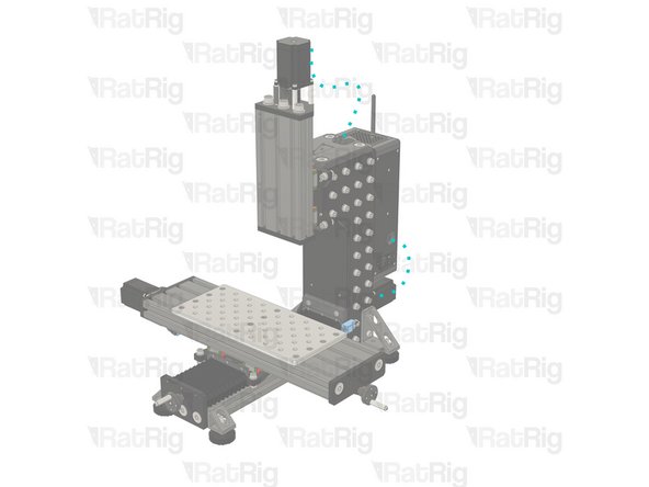
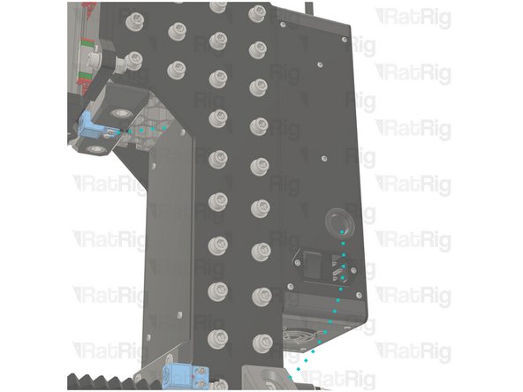
Route the Z-stepper wires as shown in the picture.
-
Route the wires to the location where you desire to have the electronics components.
-
Cut the wires to the final length, double check if the cable has the appropriate length before cutting.
-
Label the cable at the end, with a piece of duct tape for example.
-
-
-
Prepare the 4 wire cable for the X stepper motor.
-
4 Wire cable
-
Insert an Xtension (female) connector on the cable end.
-
Connect the extension to the stepper motor.
-
Make sure to follow the wire colour scheme to preserve the motor coil pairs.
-
Should the integrity of the motor coil pairs not be maintained, the motor will experience impaired operational functionality.
-
-
-
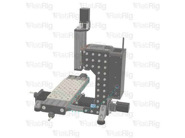
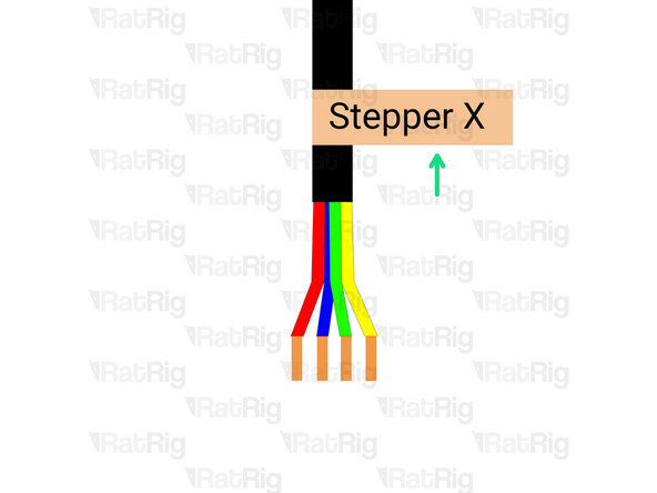
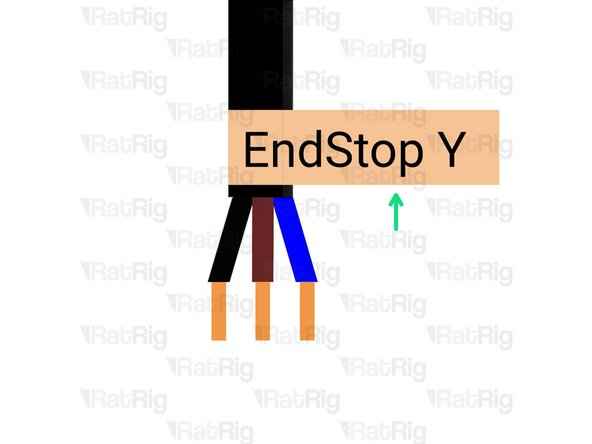
Route the endstop, and X-stepper cables as shown in the picture.
-
Route the cables to the location where you desire to have the electronics components.
-
Cut the cables to the final length, double check if the cable has the appropriate length before cutting.
-
Label the cable at the end, with a piece of duct tape for example.
-
If the endstop cable is too short, use the provided 3-wire cable and extend it following the same procedure as for the stepper motors. Make sure to respect the colour order.
-
-
-
Prepare the 4 wire cable for the Y stepper motor.
-
4 Wire cable
-
Insert an Xtension (female) connector on the cable end.
-
Connect the extension to the stepper motor.
-
Make sure to follow the wire colour scheme to preserve the motor coil pairs.
-
Should the integrity of the motor coil pairs not be maintained, the motor will experience impaired operational functionality.
-
-
-
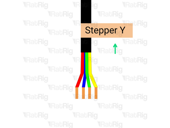
Route the endstop, Y-steppers cables as shown in the picture.
-
Route the cables to the location where you desire to have the electronics components.
-
Cut the cables to the final length, double check if the cable has the appropriate length before cutting.
-
Label the cable at the end, with a piece of duct tape for example.
-
If the endstop cable is too short, use the provided 3-wire cable and extend it following the same procedure as for the stepper motor in Step 14. Make sure to respect the colour order.
-
-
-
Insert wisdom here
-
-
-
Explain that the wires might need to be extended and the kit has wire connectors for it. but for the CCEE they don't need to be extended
-
-
-
Insert wisdom here
-
-
-
Insert wisdom here
-
-
-
Insert wisdom here
-
-
-
Insert wisdom here
-
-
-
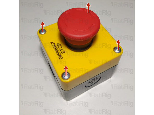
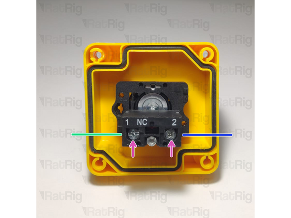
Open the emergency button by removing the four screws
-
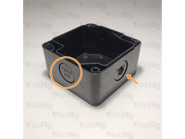
Open a hole on the emergency button body, either by snapping a removable disk or drilling a hole
-
Prepare two wires. These must be long enough to connect the button to the AXBB and place the emergency button on your desired location.
-
Insert one wire on one side
-
Tighten the screw to hold it in place
-
Insert another wire to the other side
-
Tighten the screw to hold it in place
-
Make sure to feed the wires through the hole made previously and close the emergency button with the four screws.
-
-
-
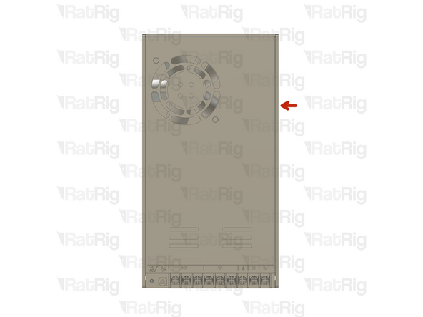
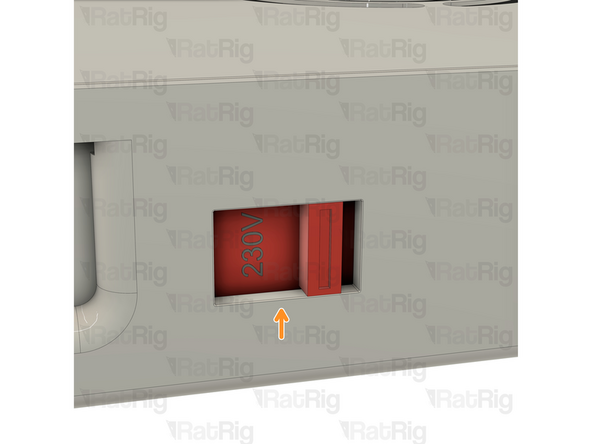
On the right side of the power supply there is a switch.
-
This switch needs to be set to the mains voltage in your country. Either 115V (most common in the USA / Canada), or 230V.
-
Setting this to the incorrect input voltage may destroy the power supply and anything connected to it.
-
Keep in mind that milling is a very messy job and debris may fly into the power supply. This could cause it to fail or catch fire! Please be aware!
-
-
-
Insert wisdom here
-
-
-
Insert wisdom here
-
-
-
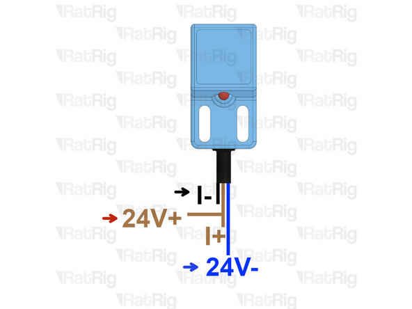
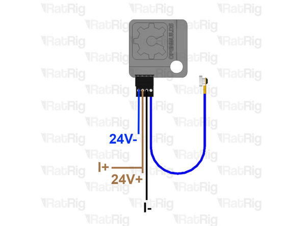
The probe has three wires, if your colours are different, please check the supplier datasheet.
-
If you are using a XYZ probe from OpenBuilds, the connector on the probe has
-
Blue - 24V- (GND)
-
Brown - 24V+ and I+ terminals.
-
Black (signal wire)- I- terminal
-
-
-
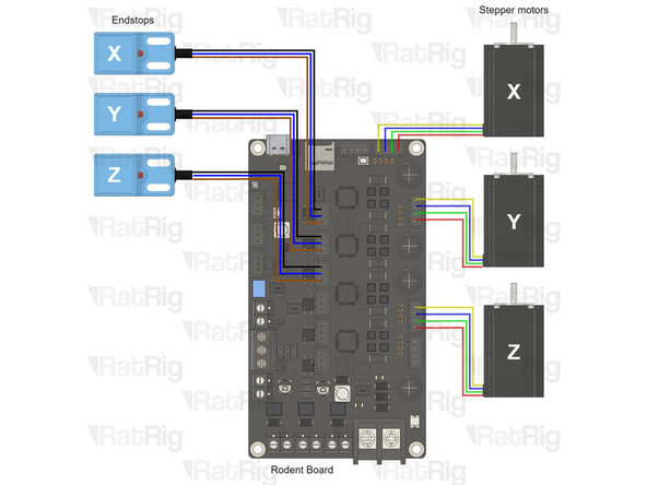
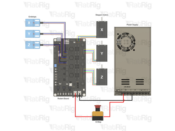
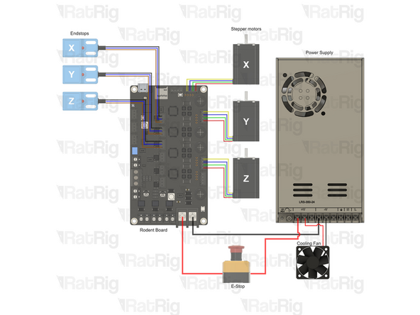
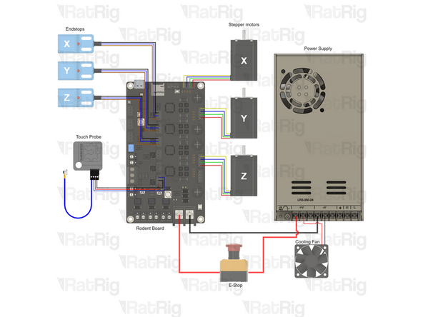
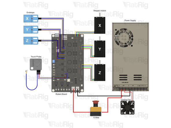
Check all the cables. The connections must look like the picture. Take your time to ensure all steps are correct before powering the machine on, any mistakes may cause component malfunction or failure.
-