
Steps
23
- 01. Frame Assembly 23 steps

User-Contributed Guide
This guide is not managed by the site's staff.
Quiz
0
Introduction
Please note: All measurements provided in this guide are based upon building a 300x300 V-Core 3.
If you are building a machine of a different size, the following adjustments can be made to the stated extrusion lengths:
- 200x200: Remove 100mm
- 400x400: Add 100mm
- 500x500: Add 200mm
It is strongly recommended to assemble the frame on a known flat surface (such as a solid table, work surface or similar). Assembling the frame on a carpeted floor, or other non-flat surface, can cause the finished frame to not be square. This can cause issues with print quality and performance.
The V-Core 3.1 frame is built upside down. This is done to aid in keeping all critical sections of the frame square.
-
-
A dedicated set of guides for building an enclosed V-Core 3.1 using the Enclosure 2.0 kit is available here.
-
Please only follow this guide when building a non-enclosed V-Core 3.1 printer.
-
-
-
2x 450mm 3030 Extrusion
-
2x 440mm 3030 Extrusion
-
1x 420mm 3030 Extrusion
-
10x 90 Degree Corner Assembly
-
-
-
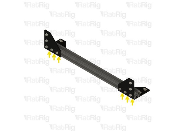
450mm 3030 Extrusion
-
440mm 3030 Extrusion
-
420mm 3030 Extrusion
-
90 Degree Corner Assembly
-
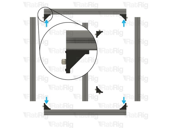
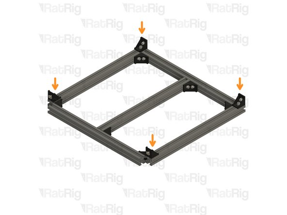
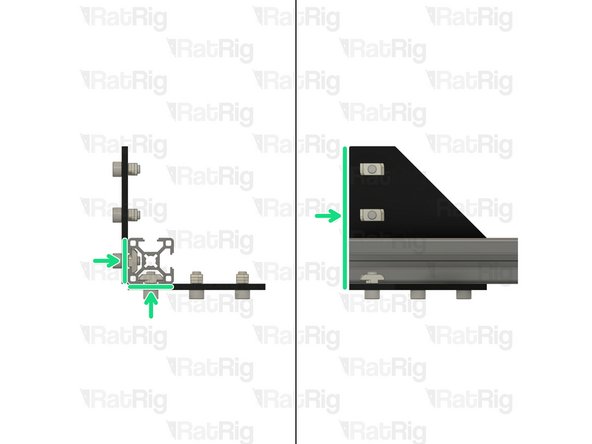
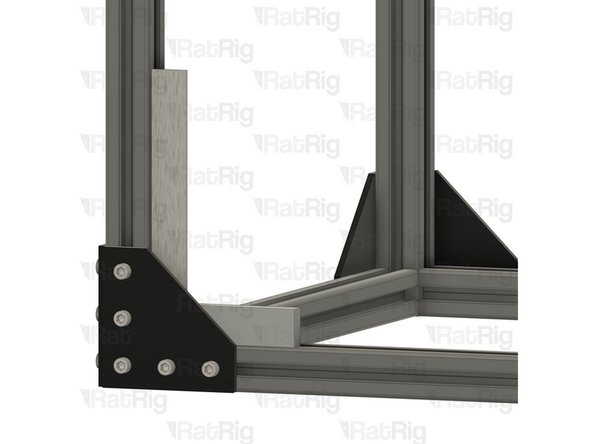
Install one corner assembly onto each end of both 440mm 3030 extrusions as shown. Tighten the M6x12 screw to secure them.
-
Ensure the corner assemblies are flush and square with the ends of the extrusions after tightening the screws
-
Assemble the 450mm and 440mm extrusions together as shown, making sure the extrusion joints are square
-
Tighten the remaining M6x12 screws to secure the exterior of the subframe together
-
-
-
420mm 3030 Extrusion
-
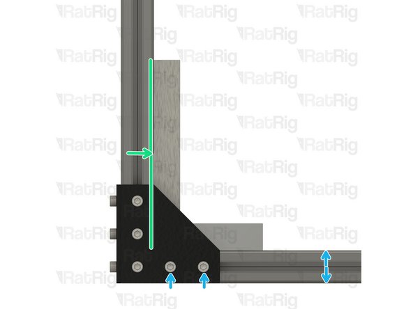
Position the extrusion as shown. The measurements shown should be equal and will be 205mm for a 300x300 frame
-
90 Degree Corner Assembly
-
Install the corner assembly as shown, and secure both M6x12 screws
-
Check that the 420mm extrusion is positioned correctly and is square
-
Install the corner assembly as shown, and secure both M6x12 screws
-
Check that the 420mm extrusion is positioned correctly and is square
-
-
-
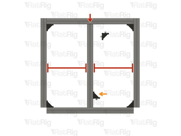
Measure both of the distances shown using a long ruler (preferred), or a tape measure. The measurements should be equal to each other, and should be as close as possible to the following:
-
200x200: 509.3mm
-
300x300: 650.7mm
-
400x400: 792.1mm
-
500x500: 933.5mm
-
If the measurements are not equal, and are not close to those shown above, double check all corners are square and then check again
-
-
-
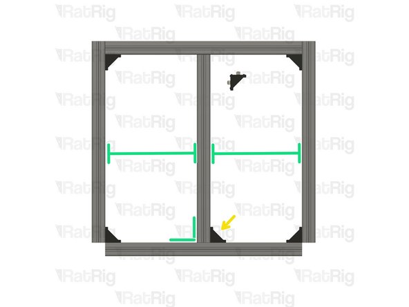
90 Degree Corner Assembly
-
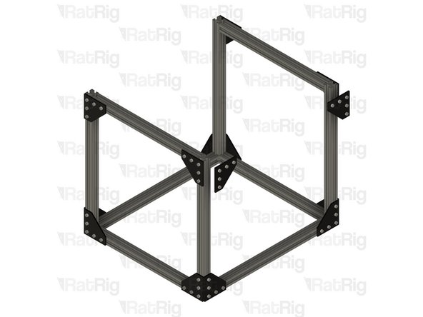
Install one corner assembly onto each position shown. Tighten the M6x12 screw to secure them.
-
Ensure the corner assemblies are flush and square with the ends of the extrusions after tightening the screws
-
Set this assembly aside until Step 15
-
-
-
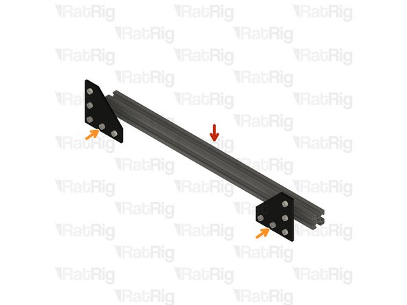
510mm 3030 Extrusion
-
Corner Plate Assembly
-
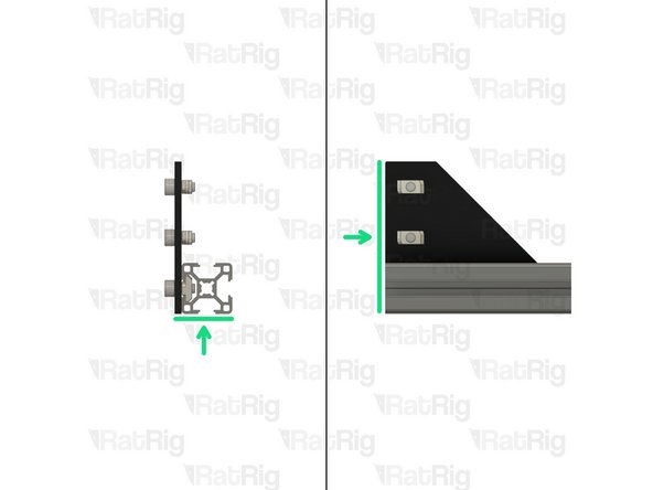
Secure the corner plates to the extrusion by fastening the five M6x12 screws
-
Check all of the corner plates to make sure they are square to the extrusion, and flush with the ends
-
-
-
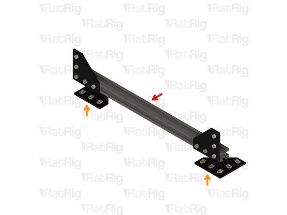
Assembly from the previous step
-
Corner plate assembly
-
Secure the corner plates to the extrusion by fastening the five M6x12 screws
-
Check all of the corner plates to make sure they are square to the extrusion, and flush with the ends
-
-
-
4x 505mm 3030 Extrusion
-
4x 440mm 3030 Extrusion
-
2x Base Corner Plate Assembly A
-
2x Base Corner Plate Assembly B
-
2x 90 Degree Corner Assembly
-
-
-
Assemblies from Step 8
-
440mm 3030 Extrusion
-
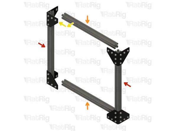
Install one 440mm 3030 extrusion onto the top and bottom of one corner assembly as shown
-
Tighten the marked M6x12 screws to secure the 3030 extrusions to the corner assembly
-
Install the opposing corner assembly onto the other ends of the 3030 extrusions as shown
-
Tighten the marked M6x12 screws to secure the corner assembly to the 3030 extrusions
-
Repeat the above steps for the second assembly
-
-
-
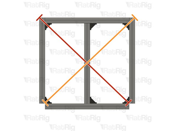
It is highly recommended to check the end assemblies for squareness before proceeding
-
End assembly
-
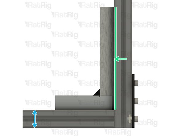
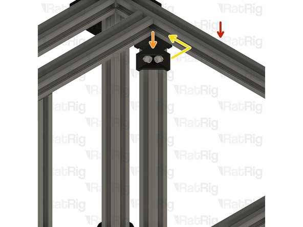
Place an engineers square on the lower 3030 extrusion as shown
-
Carefully slide the square towards the corner
-
If the connection between extrusions is square, there should be no gap between the long edge of the square and the extrusion next to it
-
If the connection is not square, loosen the M6x12 screws connecting the corner plate to this extrusion, adjust in the directions shown and then check for squareness again
-
Repeat this process for all four corners on the assembly and then repeat everything for the second end assembly
-
-
-
End Assembly
-
505mm 3030 Extrusion
-
Install one 505mm 3030 extrusion onto each side of the end assembly as shown
-
Tighten both the marked M6x12 screws, and the corresponding ones on the other side, to secure the 3030 extrusions to the end assembly
-
Install the opposing end assembly onto the other ends of the 3030 extrusions as shown
-
Tighten both the marked M6x12 screws, and the corresponding ones on the other side, to secure the end assembly to the 3030 extrusions
-
-
-
It is highly recommended to check the frame assembly for squareness before proceeding
-
Partial V-Core 3.1 Frame Assembly
-
Place an engineers square on the lower 3030 extrusion as shown
-
Carefully slide the square towards the corner
-
If the connection between extrusions is square, there should be no gap between the long edge of the square and the extrusion next to it
-
If the connection is not square, loosen the M6x12 screws connecting the corner plate to this extrusion, adjust in the directions shown and then check for squareness again
-
Repeat this process for all four corners on the partial frame assembly
-
-
-
To proceed with the assembly, the four marked corner plate assemblies must be removed
-
Corner Plate Assembly to remove
-
Loosen the three marked M6x12 screws on each plate and place them aside
-
You will require two of the corner plate assemblies for Step 17 and two for Step 19
-
-
-
If you plan to use an electronics panel, it is highly recommended to assemble and install it now. Installing a single, large, panel after further assembly is not possible
-
If you do not plan to use an electronics panel, or plan to use a split panel, you may skip to Step 17
-
22x M6x12mm Cap Head Screw
-
22x M6 Washer
-
22x 3030 Drop-in T-Nut - M6
-
Electronics Panel Assembly
-
3x Cable Guide Printed Part ( Provided in the Electronics Extra Kit )
-
Fasten all M6x12 screws to secure the electronics panel to the electronics subframe assembly
-
-
-
V-Core 3.1 Frame Assembly
-
Electronics Subframe Assembly
-
Pay attention to the orientation of the electronics subframe
-
Slot the electronics subframe assembly into the V-Core 3.1 frame assembly as shown
-
The gap shown between the V-Core 3.1 frame and the electronics subframe should measure 47mm minus the thickness of your electronics panel on all machine sizes
-
For example: Using a 4mm thick electronics panel, the gap would measure 43mm (47mm minus 4mm)
-
Once positioned correctly, tighten the marked M6x12 screws to secure the electronics subframe in place
-
-
-
505mm 3030 Extrusion
-
Place the 505mm 3030 extrusion into the frame as shown
-
Tighten the marked M6x12 screw to secure the 505mm 3030 extrusion to the electronics subframe
-
Re-install the two 90 degree corner assemblies as shown
-
Tighten all of the M6x12 screws on the two 90 degree corner assemblies
-
-
-
V-Core 3.1 frame assembly
-
90 degree corner assembly
-
Install the corner assembly into the corner of the two 3030 extrusions as shown
-
Tighten both M6x12 screws to secure the corner assembly to both the main frame and the subframe
-
-
-
505mm 3030 Extrusion
-
Place the 505mm 3030 extrusion into the frame as shown
-
Tighten the marked M6x12 screw to secure the 505mm 3030 extrusion to the electronics sub frame
-
Re-install the two 90 degree corner assemblies as shown
-
Tighten all of the M6x12 screws on the two 90 degree corner assemblies
-
-
-
V-Core 3.1 frame assembly
-
90 degree corner assembly
-
Install the corner assembly into the corner of the two 3030 extrusions as shown
-
Tighten both M6x12 screws to secure the corner assembly to both the main frame and the subframe
-
-
-
Base corner plate assembly A
-
Base corner plate assembly B
-
Install each corner plate assembly onto the marked corners
-
Tighten the three marked M6x12 screws on each corner plate
-
Tighten the marked M5x18 screw on each corner plate
-
Turn the V-Core 3.1 frame assembly over, and rest it on its feet
-


Cancel: I did not complete this guide.
27 other people completed this guide.
One Comment
I think it is worth to update the frame build guide couse this one builds the most important parts at the end. Check this video: