
Steps
36
- 01. V-Core 3.0 to 3.1 Upgrade Guide 36 steps

User-Contributed Guide
This guide is not managed by the site's staff.
Quiz
0
Introduction
This guide covers the disassembly of a V-Core 3.0 machine to prepare it for the 3.1 upgrade.
As a large number of components will be re-used for 3.1, it is recommended to sort them during disassembly so that they are easily found during the 3.1 build process.
-
-
Your EVA2 assembly may differ from the one shown. The EVA2 sections of this guide should be used as general advice for disassembly.
-
Remove the four M3x20 screws
-
Remove the EVA2 shroud
-
Remove the 40x10mm hot end fan
-
-
-
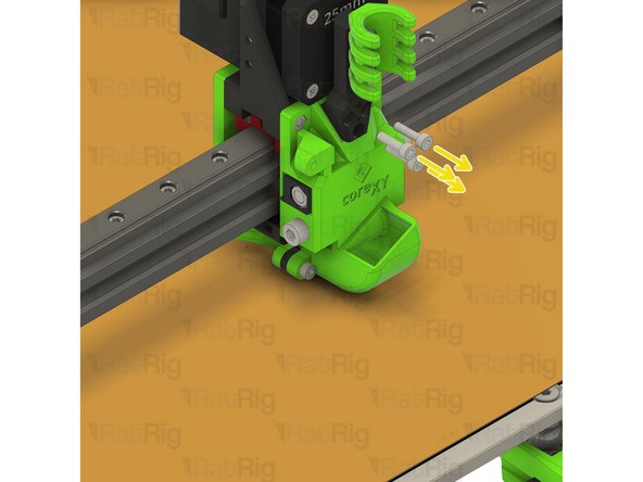
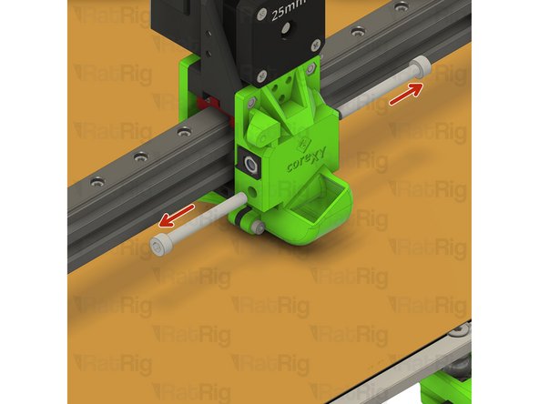
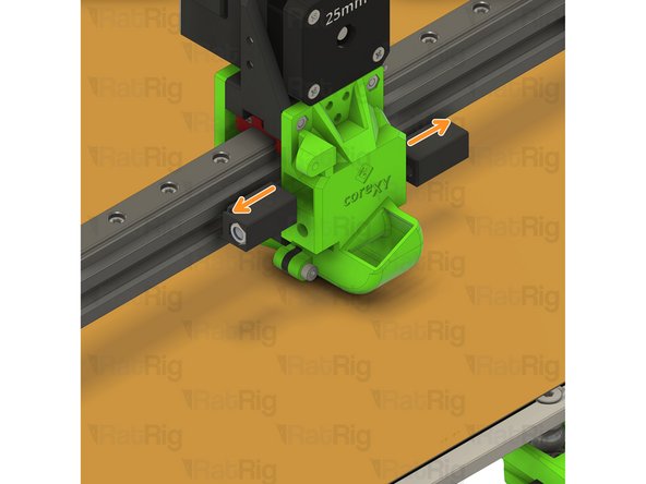
Remove the two marked M3x25 screws
-
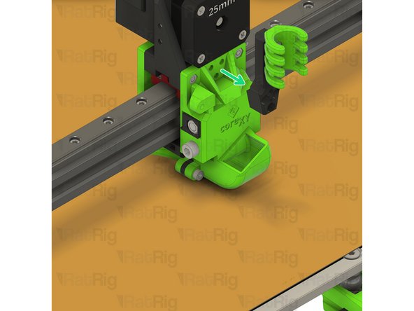
Remove the hot end assembly
-
-
-
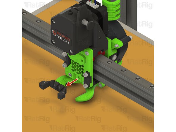
Remove the lower face support
-
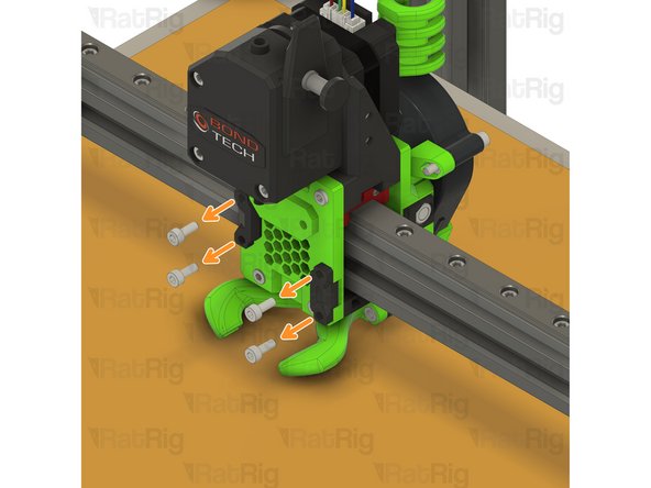
Remove the four M3x8 screws
-
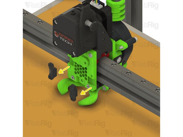
Remove both belt grabbers and free the CoreXY belts
-
-
-
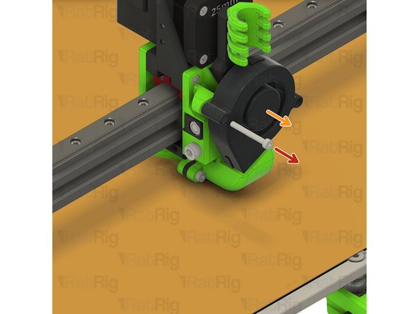
Remove the M3x25 screw securing the 5015 fan
-
Remove the 5015 fan
-
Remove the three M3x12 screws securing the cable holder
-
Remove the cable holder assembly
-
-
-
Remove the two M5x45 screws securing the belt grabbers into the EVA2 back
-
Pull the belt to remove the belt grabbers
-
Remove the belt from the belt grabbers
-
Slowly pull one end of the first belt to remove it from the CoreXY drive mechanism
-
Repeat to free the second belt
-
-
-
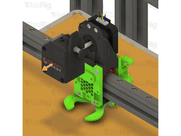
Remove the three M3x35 screws from the Bondtech BMG extruder
-
Remove the Bondtech BMG extruder
-
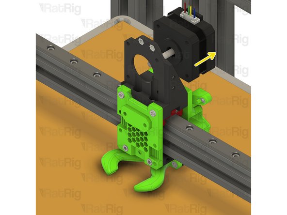
Remove the extruder NEMA17 stepper motor
-
Leave the remainder of the EVA2 assembly for now. It will be further disassembled in Step 32
-
-
-
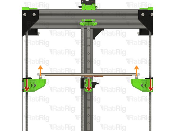
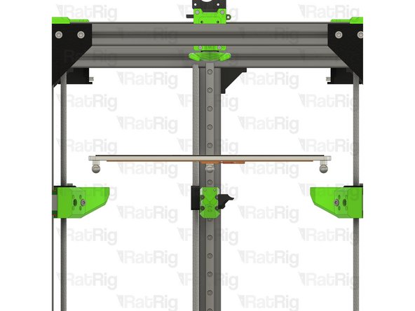
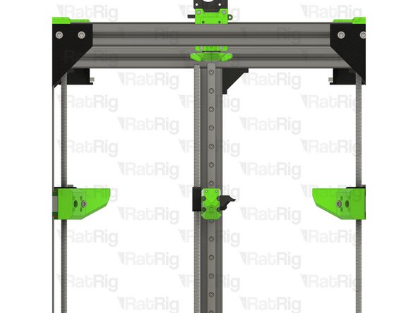
Lower the z-axis by turning each lead screw counter-clockwise
-
Lift the bed assembly upwards to raise it off of the arms
-
Disconnect the heated bed wiring and set it aside for the V-Core 3.1 assembly
-
-
-
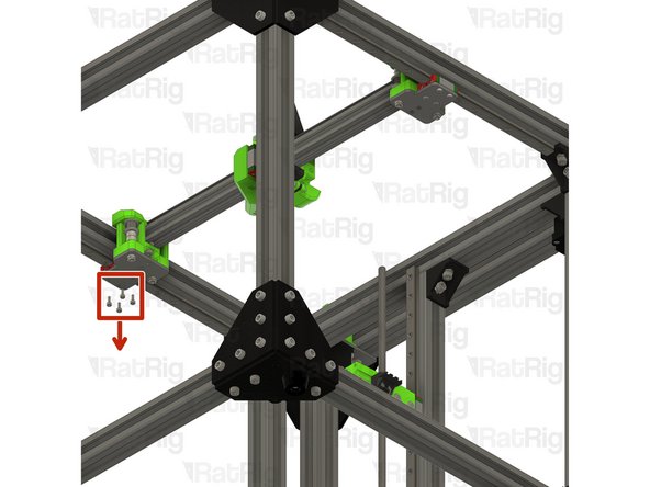
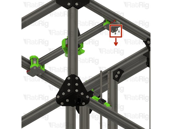
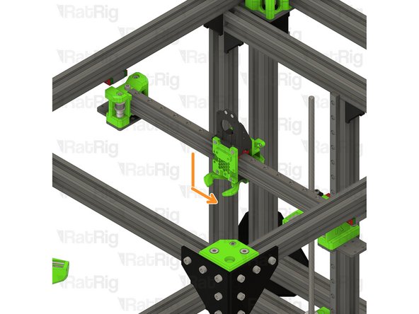
Whilst supporting the x-axis assembly, remove the eight marked M3x8 screws
-
Remove the x-axis assembly from the V-Core 3 and set it aside until Step 30
-
-
-
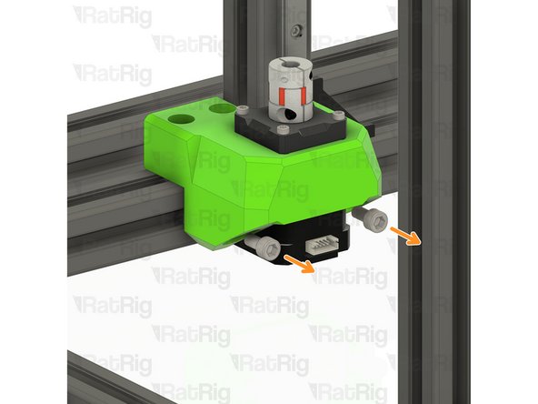
Remove the two marked M5x35 screws from the front left arm
-
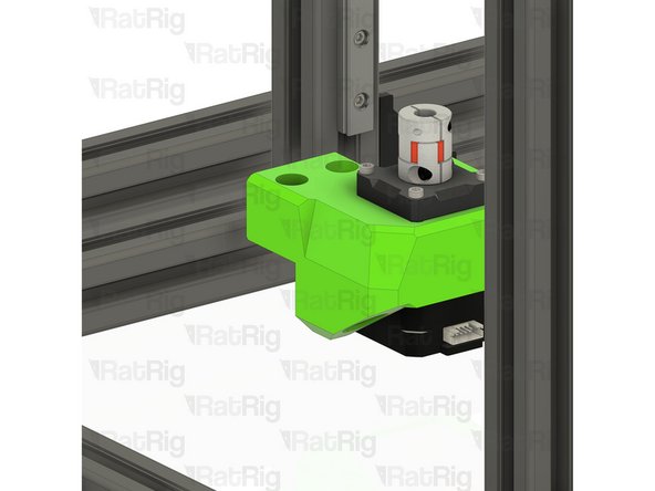
Remove the four M3x20 screws from the front left arm
-
Repeat the above 2 steps to remove the front right arm
-
Set the both front bed arms aside until Step 27
-
-
-
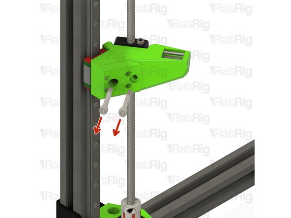
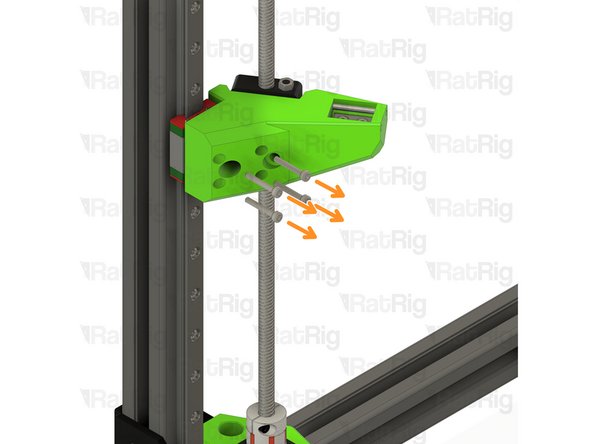
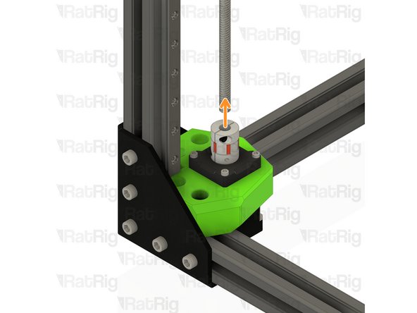
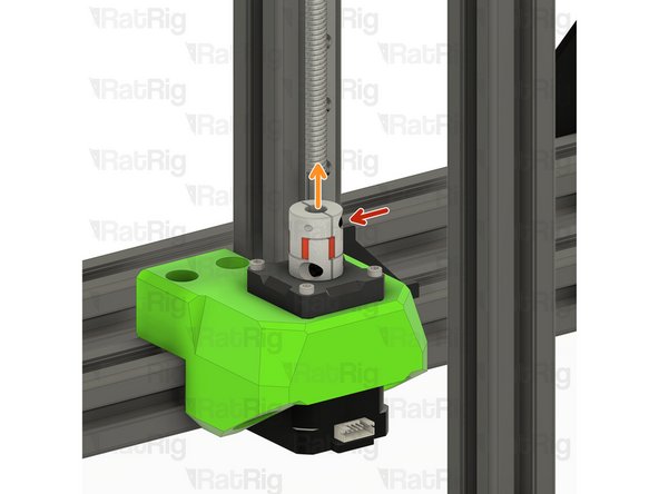
Loosen the upper M3 screw on the lead screw coupler
-
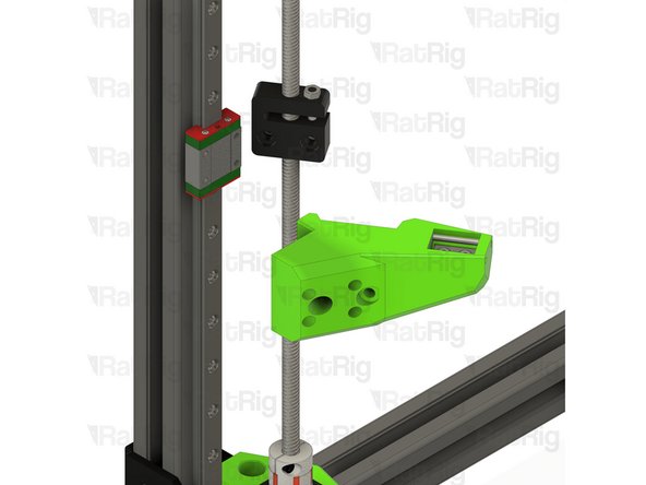
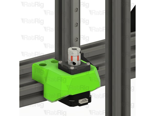
Gently pull the lead screw upwards and out of the coupler
-
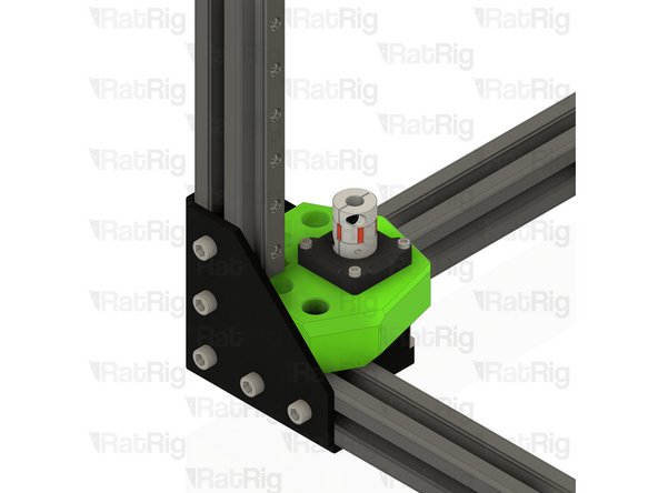
Remove the anti-backlash nut block from the lead screw
-
Repeat the above 3 steps for the lead screw at the front right side
-
-
-
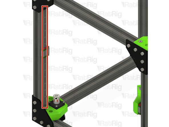
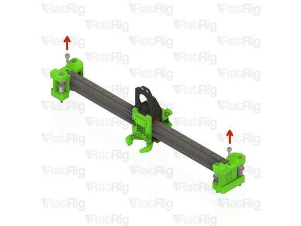
Loosen all of the M3 screws securing the linear rail to the V-Core 3.0 frame
-
Remove the linear rail, taking care not to let the carriage leave either end of the rail
-
Repeat the above two steps for the linear rail on the front right
-
Set the linear rail assemblies aside, they will be re-installed during the V-Core 3.1 assembly guide
-
-
-
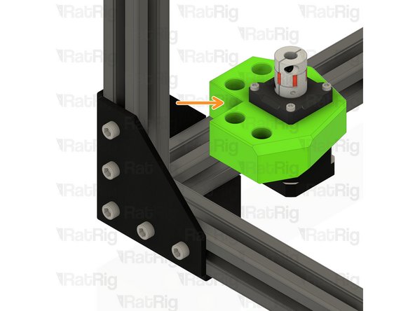
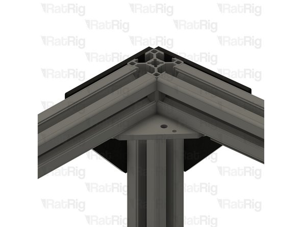
Remove the four marked M6x20 screws
-
Remove the front left z-axis motor mount
-
Retrieve the four 3030 drop-in t-nuts from the 3030 extrusion
-
Repeat the above three steps for the motor mount on the front right side
-
Set both assemblies aside until Step 25
-
-
-
Remove the two marked M5x35 screws from the rear bed arm
-
Remove the four M3x20 screws from the rear bed arm
-
Set the rear bed arm aside until Step 28
-
-
-
Loosen the upper M3 screw on the lead screw coupler
-
Gently pull the lead screw upwards and out of the coupler
-
Remove the anti-backlash nut block from the lead screw
-
Set the lead screw aside, along with the other two, for use during the V-Core 3.1 assembly
-
-
-
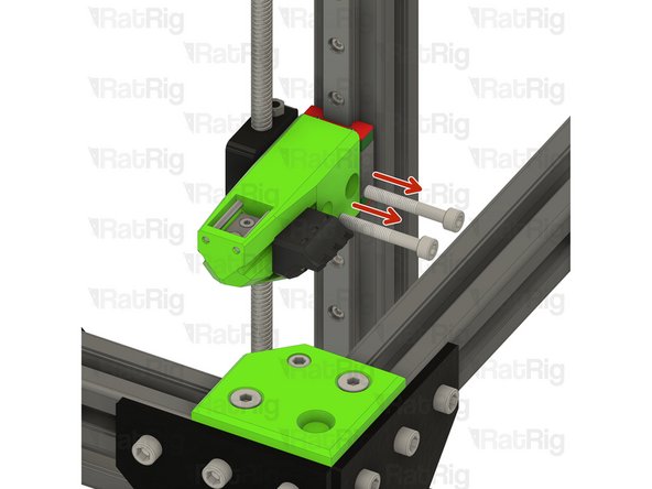
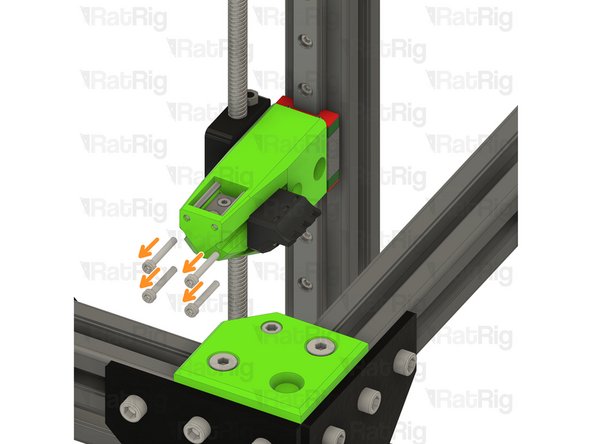
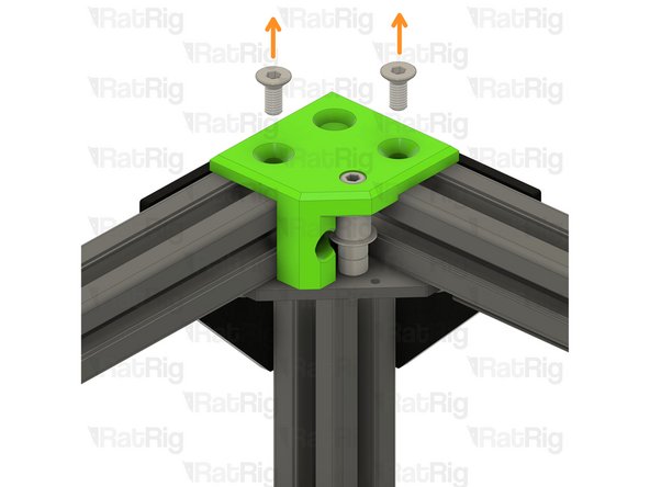
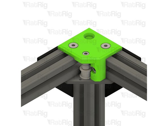
Remove the two marked M6x20 screws
-
Remove the two marked M6x12 screws
-
Retrieve the four 3030 drop-in t-nuts from the 3030 extrusion
-
Set this assembly aside until Step 25
-
-
-
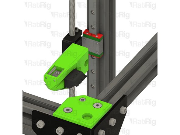
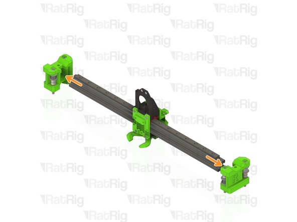
Loosen all of the M3 screws securing the linear rail to the V-Core 3.0 frame
-
Remove the linear rail, taking care not to let the carriage leave either end of the rail
-
Set the linear rail assembly aside, it will be re-installed during the V-Core 3.1 assembly guide
-
-
-
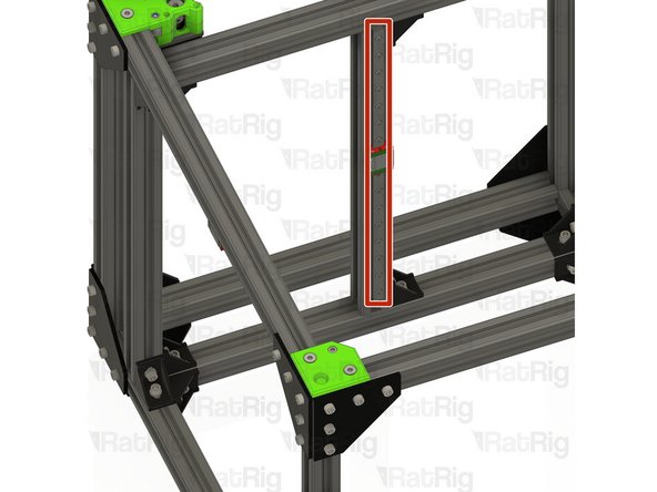
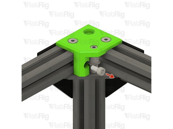
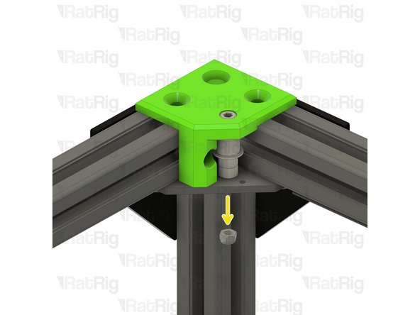
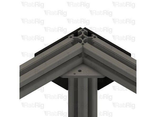
Remove the marked M6x12 screw
-
Remove the two marked M6x14 countersink screws
-
Remove the M5 nylon locking nut from the underside of the idler bracker
-
-
-
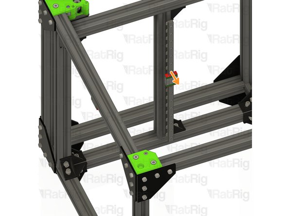
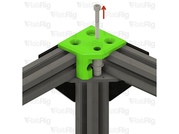
Remove the marked M5x40 screw
-
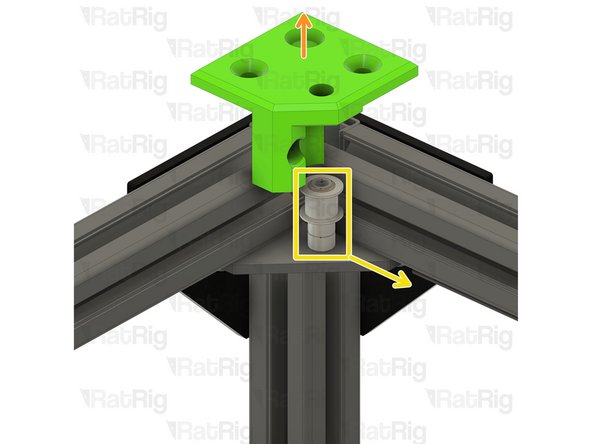
Lift the xy_idler printed part off the V-Core 3.0 frame
-
Remove all components of the idler stack
-
Retrieve the three 3030 drop-in t-nuts from the 3030 extrusion
-
-
-
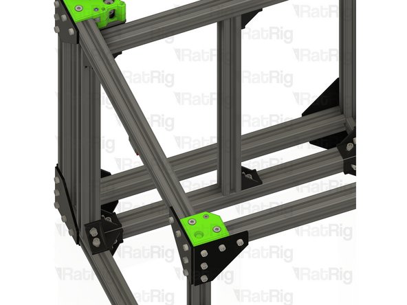
Repeat the previous step to disassemble the front right idler
-
-
-
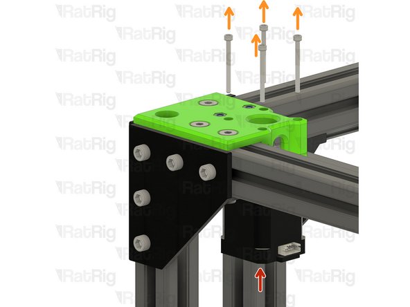
Support the NEMA17 stepper motor
-
Remove the four marked M3x35 screws
-
Remove the NEMA17 stepper motor from the mount
-
-
-
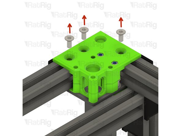
Remove the three marked M6x14 countersink screws
-
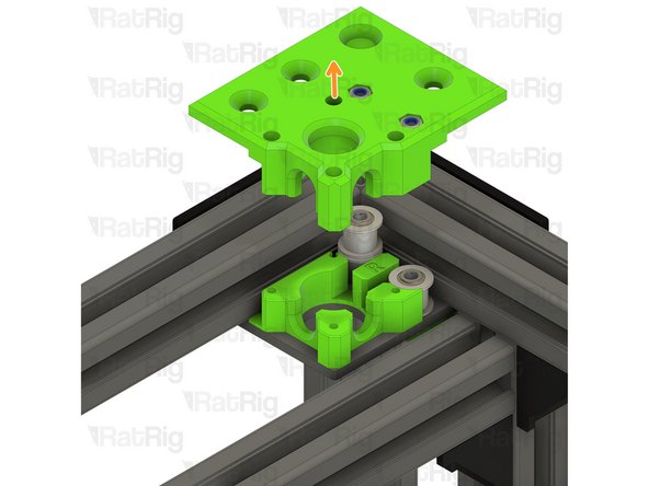
Lift off the top of the CoreXY motor mount
-
Retrieve the three 3030 drop-in t-nuts from the 3030 extrusion
-
Remove the lower part of the CoreXY motor mount
-
-
-
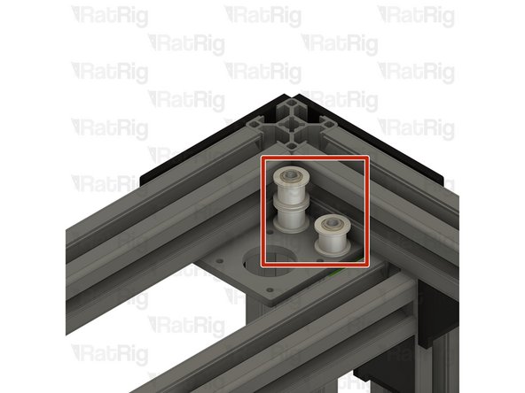
Remove all components of the two idler stacks
-
-
-
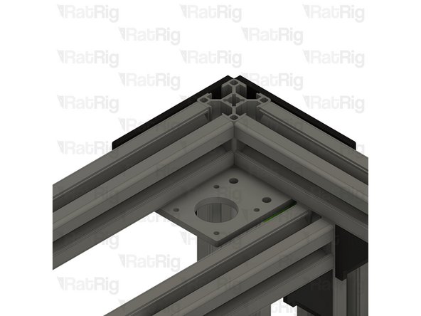
Repeat Steps22 and 23 to disassemble the left CoreXY motor assembly
-
-
-
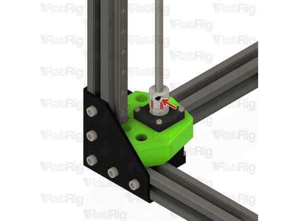
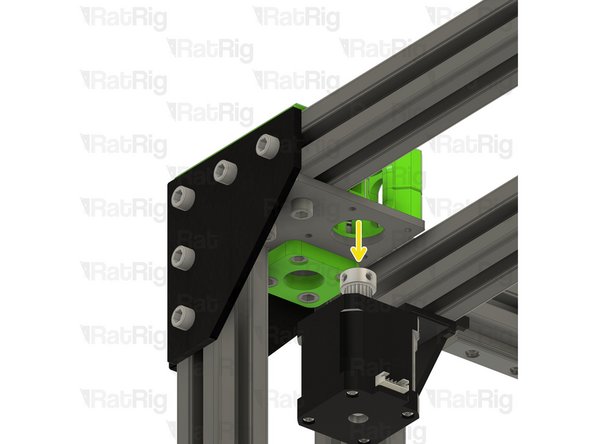
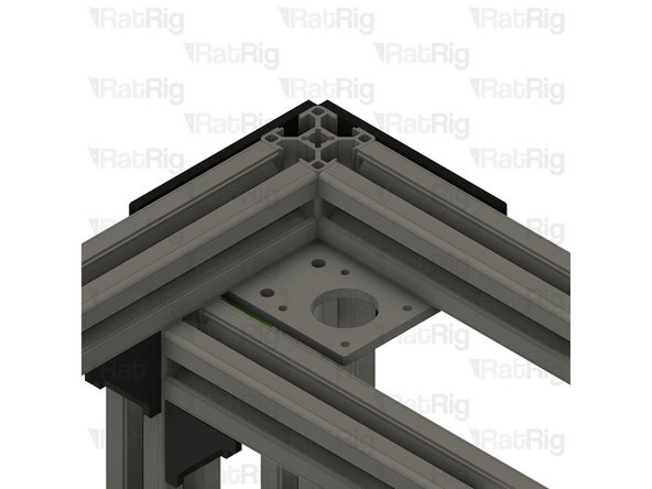
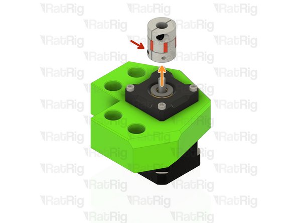
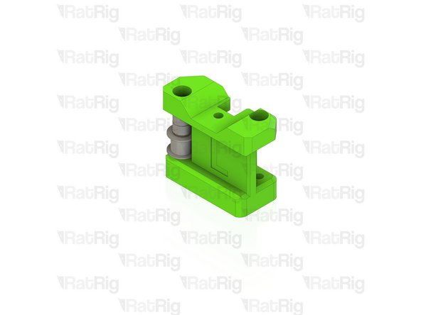
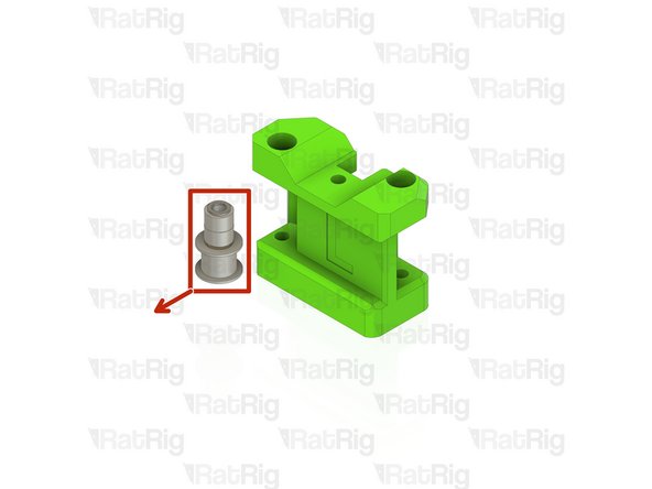
Loosen the lower M3 screw on the lead screw coupler
-
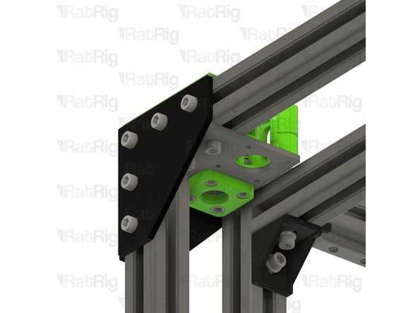
Remove the lead screw coupler
-
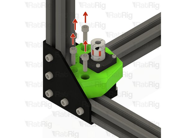
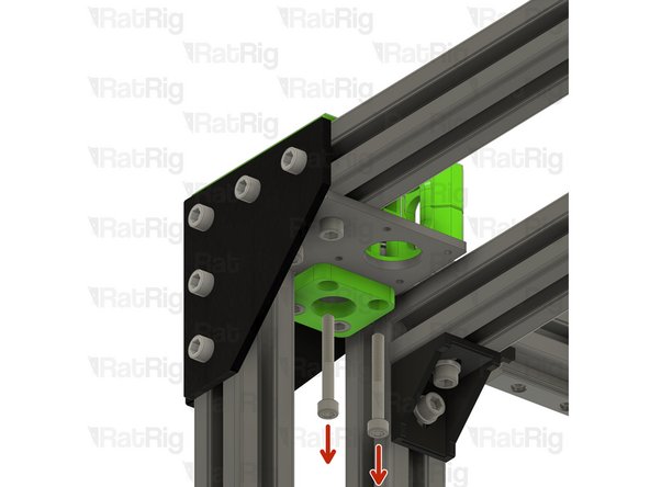
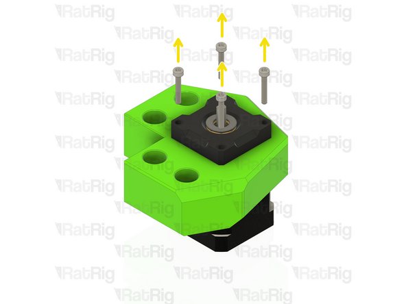
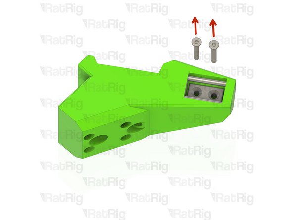
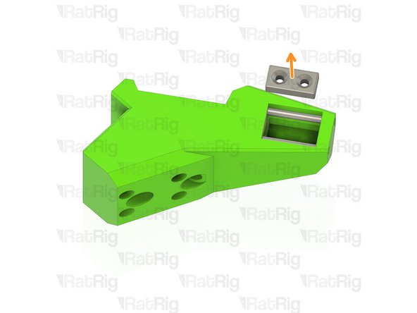
Remove the four marked M3x18 screws
-
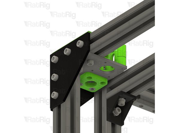
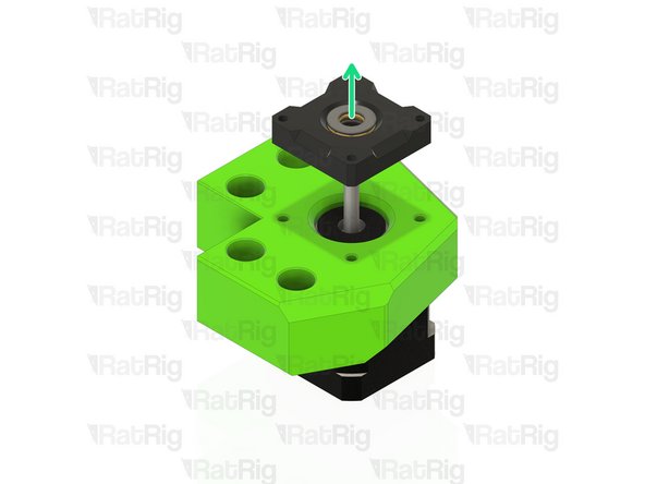
Lift the pillow block assembly off and set it aside
-
-
-
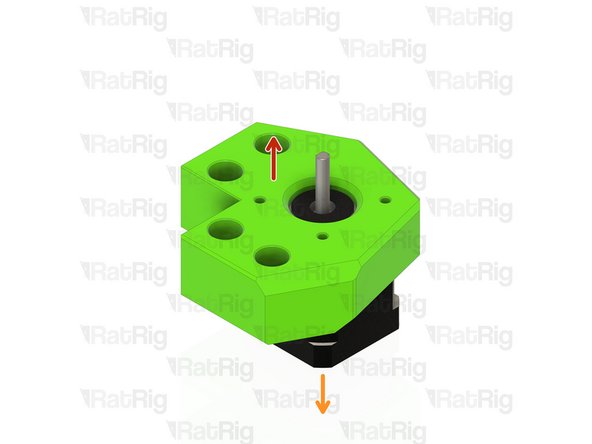
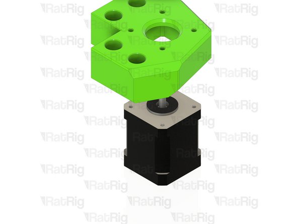
Remove the printed mount from the NEMA17 stepper motor
-
Set the NEMA17 stepper motor aside for the V-Core 3.1 assembly guide
-
Repeat Step 25 and the above two steps for the other two z-axis motor mounts
-
-
-
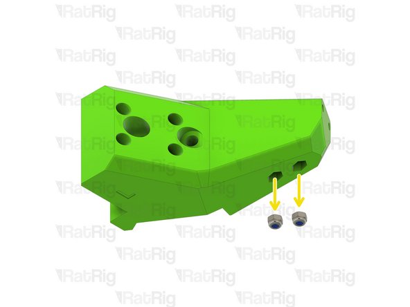
Remove the two marked M3x20 countersink screws
-
Remove the neodymium magnet
-
Remove the two M3 nylon locking hex nuts
-
Repeat the above three steps for the front right bed arm
-
-
-
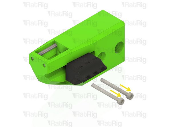
Remove the two marked M3x20 countersink screws
-
Remove the neodymium magnet
-
Remove the two marked M3x30 screws
-
-
-
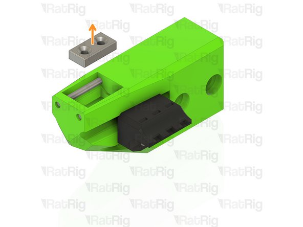
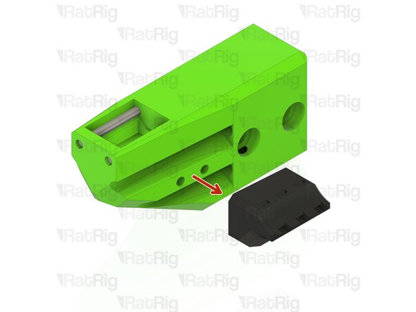
Remove the bed cable tiedown printed part
-
Remove the four marked M3 nylon locking hex nuts
-
-
-
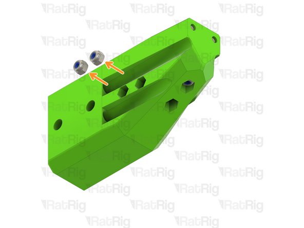
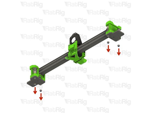
Remove the four marked M5 nylon locking hex nuts
-
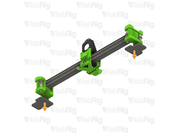
Remove both xy_joiner_plates
-
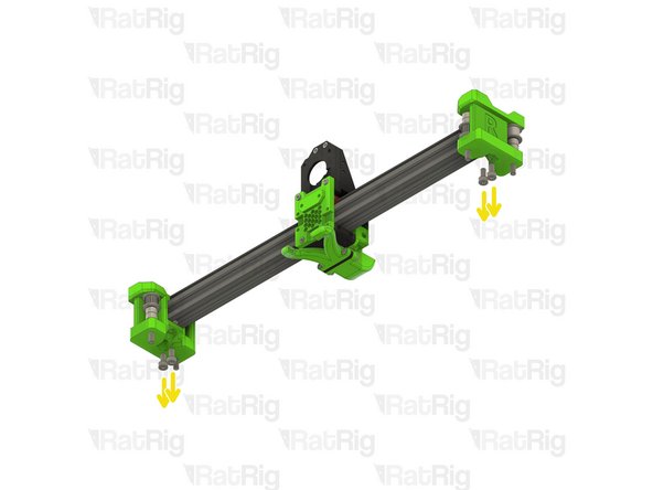
Remove the four marked M5x10 screws
-
-
-
Remove the two marked M5x12 screws
-
Remove both xy_joiners from the ends of the 2020 extrusion
-
Retrieve the six 2020 square t-nuts from the 2020 extrusion (three at each end)
-
-
-
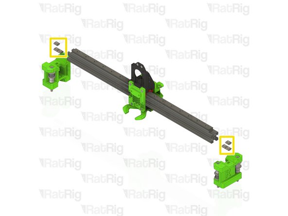
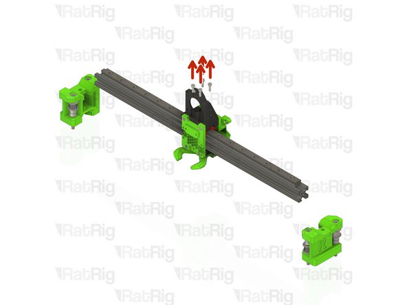
Remove the four M3x10 screws securing the remaining EVA2 assembly to the linear rail carriage
-
Remove the remaining EVA2 assembly from the 2020 extrusion and linear rail assembly as shown
-
Set the 2020 extrusion and linear rail assembly aside, as it will be needed during the V-Core 3.1 assembly
-
-
-
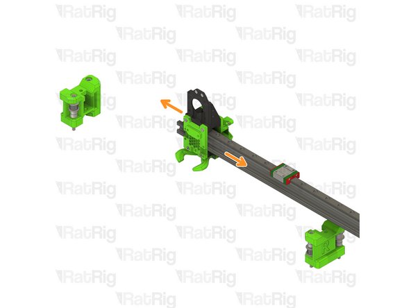
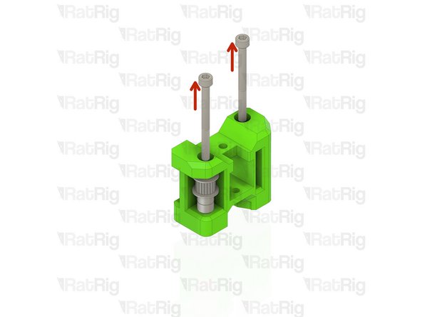
Remove the two marked M5x55 screws from the xy_joiner assembly
-
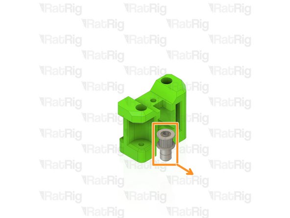
Remove all components of the front toothed idler stack
-
Repeat the above two steps for the opposite xy_joiner
-
-
-
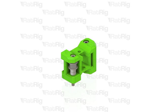
Remove all components of the rear idler stack on both xy_joiner assemblies
-
-
-
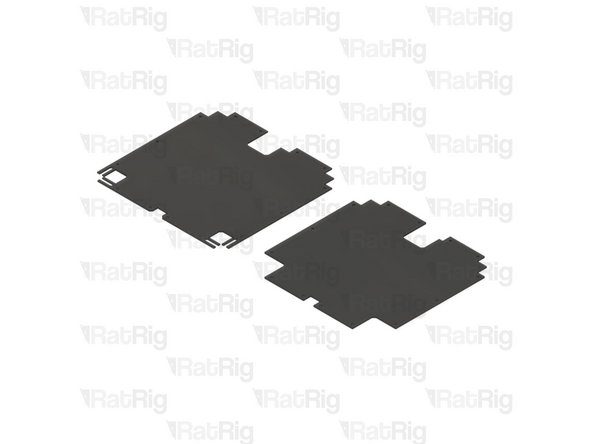
It is possible to reuse the V-Core 3.0 base panel with the V-Core 3.1 upgrade, however additional cuts will be required
-
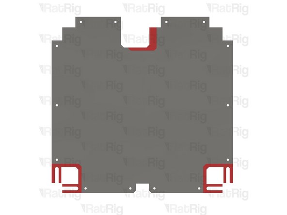
A 2D printable template, as well as a modified rear motor trim are provided on the V-Core 3.0 to 3.1 Upgrade Page
-
Refer to the provided image to align the templates for cutting the base panel
-
-
-
This completes the required disassembly for the V-Core 3.0. Further instructions for building the V-Core 3.1 are found in the following guide:
-
-


Cancel: I did not complete this guide.
12 other people completed this guide.