Introduction
BEFORE STARTING:
Before beginning this guide, you must prepare all the necessary wires for the assembly. Below is a list of the required wires. The following nomenclature will be used: (Wire Length)_(AWG)_(Wire Color)_(A-End Connector)_(B-End Connector)_(ID number).
Use a small piece of tape to label each wire to ensure a smooth assembly process.
- 700mm - 16AWG RED (A-Fork, B-Ferrule) (0)
- 700mm - 16AWG RED (A-Fork, B-Fork) (1)
- 150mm - 16AWG RED (A-Fork, B-Ferrule) (2)
- 440mm - 16AWG RED (A-Fork, B-Ferrule) (3)
-
-
CNC Electronics Contactor
-
VFD
-
8x Hex Locking Nut - M4
-
8x M4x16 Cap Head Screw
-
8x M4 washer
-
-
-
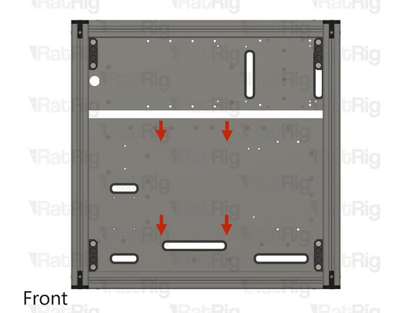
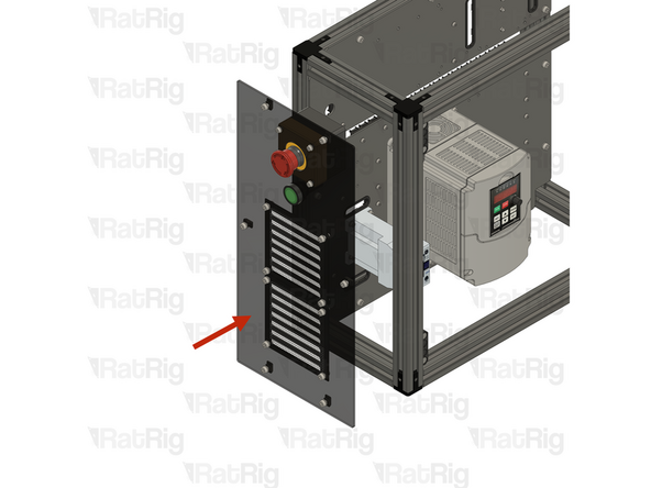
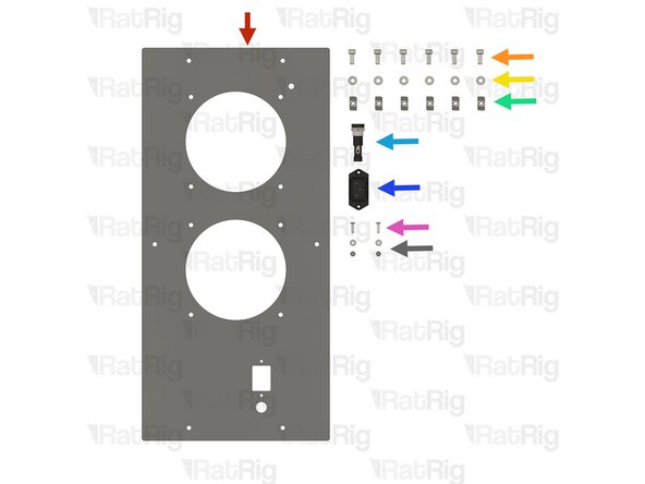
Install the component using the designated holes.
-
4x Hex Locking Nut - M4
-
CNC Electronics Contactor
-
4x M4x16 Cap Head Screw + M4 washer
-
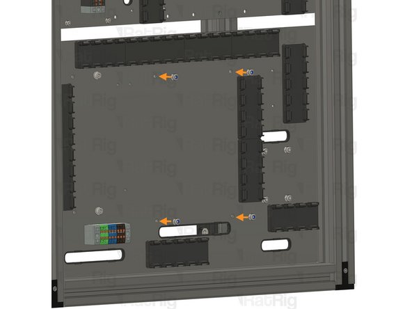
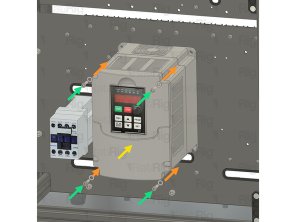
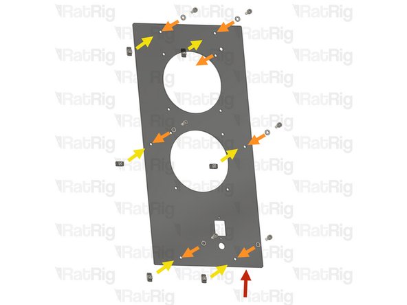
Insert the M4x16 cap head screws with M4 washers into the contactor mounting holes, then through the plate. Finally, secure them by fastening to the M4 hex locking nuts on the back.
-
-
-
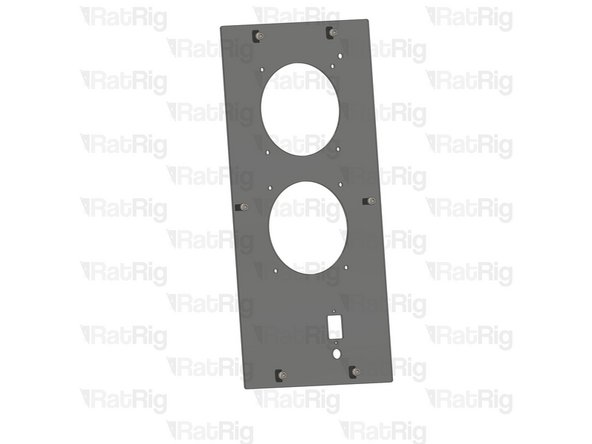
Install the component using the designated holes.
-
4x Hex Locking Nut - M4
-
VFD
-
4x M4x16 Cap Head Screw + M4 washer
-
Insert the M4x16 cap head screws with M4 washers into the VFD mounting holes, then through the plate. Finally, secure them by fastening to the M4 hex locking nuts on the back.
-
-
-
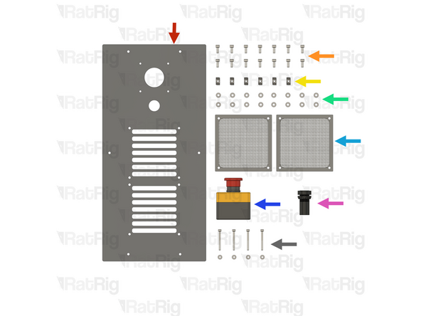
Rat Rig Universal CNC Electronics Enclosure - Left
-
12x M5x12 Cap Head Screw
-
6x 3030 Drop-in T-Nut - M5
-
12x M5 Washer
-
2x Filter - 120mm
-
Emergency stop button
-
CNC Electronics Start Button Switch - Green
-
4x M4x40 Cap Head Screw + M4 washer
-
-
-
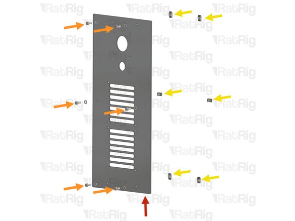
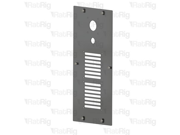
Rat Rig Universal CNC Electronics Enclosure - Left
-
(6x) M5x12 Cap Head Screw + M5 Washer
-
6x 3030 Drop-in T-Nut - M5
-
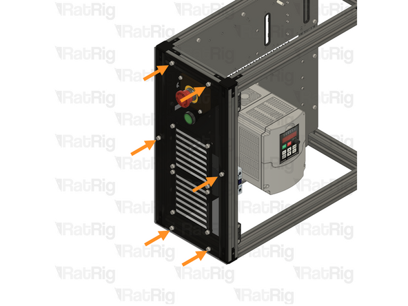
Insert an M5x12 Cap Head Screw into each marked hole on the right panel and loosely tighten a M5 drop-in T-nut to each screw.
-
-
-
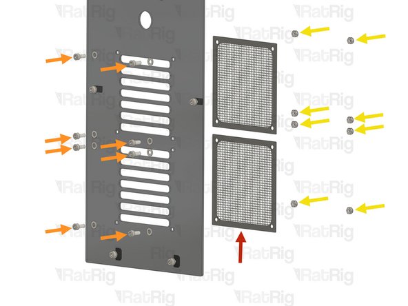
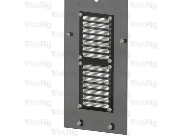
2x Filter - 120mm
-
(8x) M5x12 Cap Head Screw + M5 Washer
-
8x Hex Locking Nut - M5
-
Insert the M5x12 cap head screws through the M5 washers, then feed them into the left panel and through the filters. Finally, secure them by fastening to the M5 hex locking nuts.
-
-
-
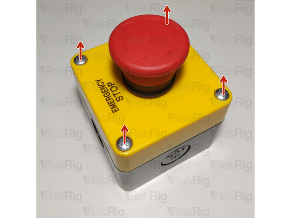
Open the emergency button by removing the four screws
-
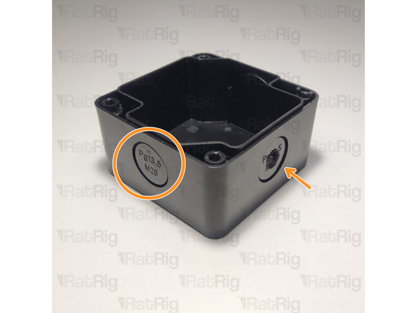
Open a hole on the emergency button body, either by snapping a removable disk or drilling a hole
-
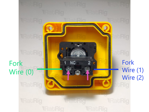
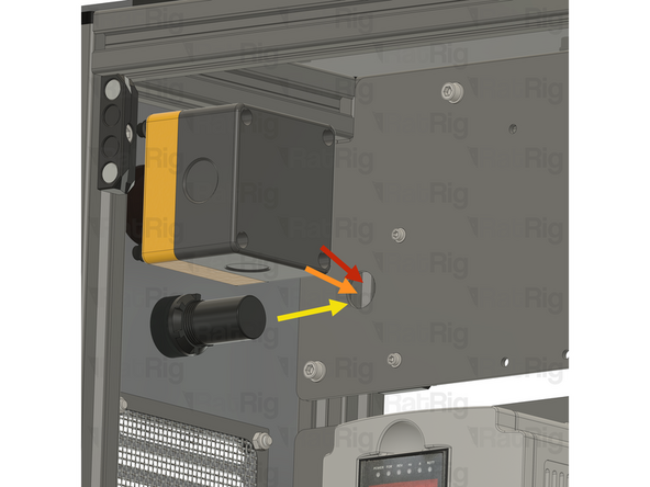
Insert the fork end of wire (0) into the shown terminal.
-
Insert the fork end of the wire (1) and the fork end of wire (2) into the shown terminal
-
Tighten the screws on the terminals.
-
After insertion, attempt to pull the wire to verify that it is securely attached.
-
Install the black cover on the E-stop button, don't use the screws.
-
-
-
Emergency stop button
-
4x M4x40 Cap Head Screw + M4 washer
-
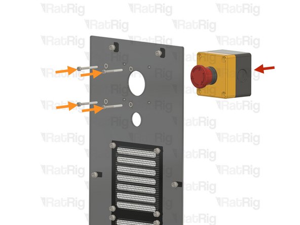
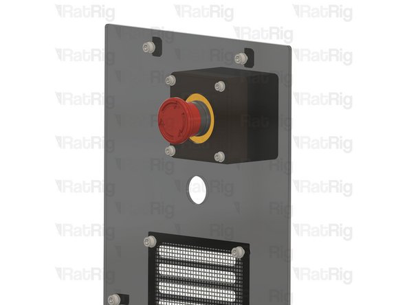
Insert the M4x40 cap head screws through the M4 washers, then into the left panel, and secure them by fastening to the E-stop button.
-
-
-
CNC Electronics Start Button Switch - Green
-
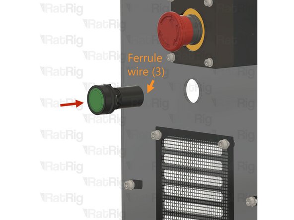
Insert the ferrule end of wire (3) in one of the start button terminals.
-
Insert the Start button and wires through the left panel.
-
Start button panel nut
-
Thread the start button panel nut onto the start button to secure it to the panel.
-
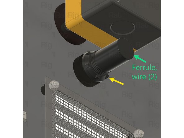
Insert the ferrule end of wire (2) coming from the E-stop button in the other start button terminal.
-
-
-
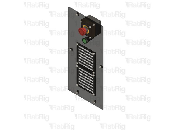
Install the left panel assembly to the Frame as shown.
-
Secure the left panel assembly to the frame by fastening the M5 cap head screws.
-
-
-
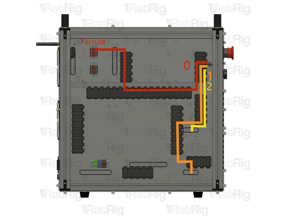
Insert wire (0) from the E-stop button into the panel hole. Guide it through the shown path and insert the ferrule end into the +24V PTFix block.
-
After insertion, attempt to pull the wire to verify that it is securely attached.
-
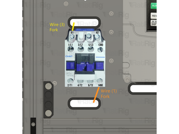
Insert wire (1) from the E-stop button into the panel hole. Guide it trough the shown path and insert it back into the designated slot. Lastly, secure the fork connector on the 14NO terminal of the Contactor.
-
Insert wire (3) from the start button into the panel hole. Guide it through the shown path and insert it back into the designated slot. Lastly, secure the fork connector on the A1 terminal of the Contactor.
-
After insertion, attempt to pull the wire to verify that it is securely attached.
-
-
-
Rat Rig Universal CNC Electronics Enclosure - Right
-
6x M5x12 Cap Head Screw
-
6x M5 Washer
-
6x 3030 Drop-in T-Nut - M5
-
Fuse Holder
-
IEC Socket
-
2x M3x12 Countersink Screw
-
2x Hex Locking Nut - M3 + M3 Washer
-
-
-
Rat Rig Universal CNC Electronics Enclosure - Right
-
(6x) M5x12 Cap Head Screw + M5 Washer
-
6x 3030 Drop-in T-Nut - M5
-
Insert an M5x12 Cap Head Screw into each marked hole on the right panel and loosely tighten a M5 drop-in T-nut to each screw.
-
-
-
Fuse Holder
-
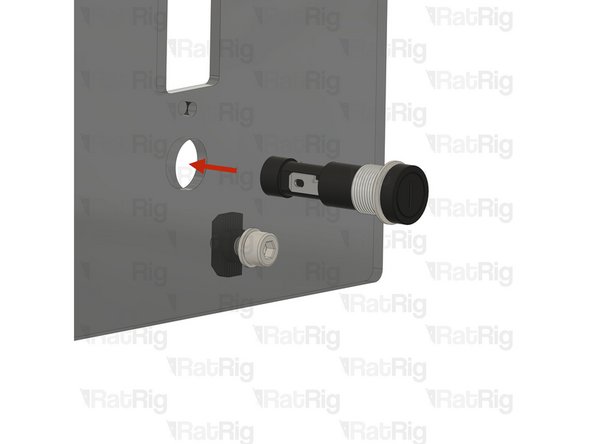
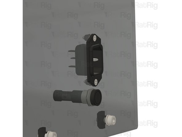
Insert the fuse holder through the left panel.
-
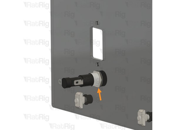
Start button panel nut
-
Thread the start button panel nut onto the start button to secure it to the panel.
-
-
-
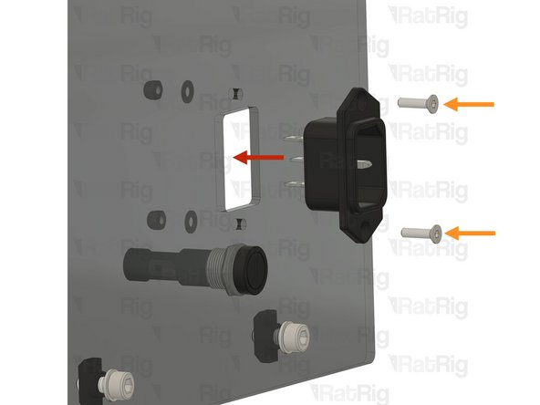
IEC Socket
-
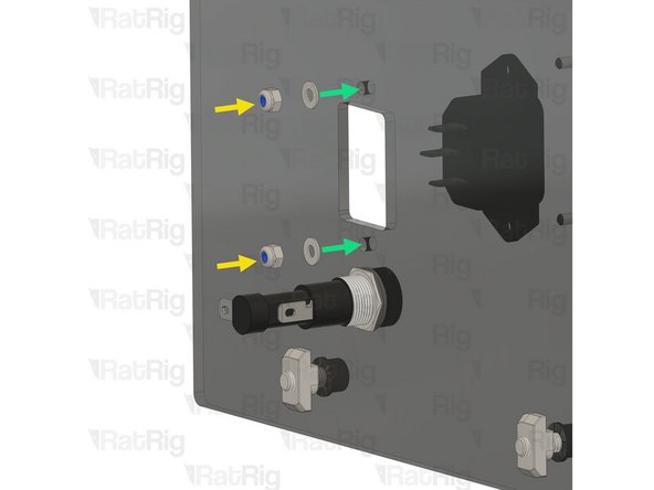
2x M3x12 Countersink Screw
-
2x Hex Locking Nut - M3
-
M3 Washer
-
Insert the IEC socket into the right panel, then feed two M3x12 countersink screws through the socket and panel. Secure the assembly using a washer and hex locking nut.
-
-
-
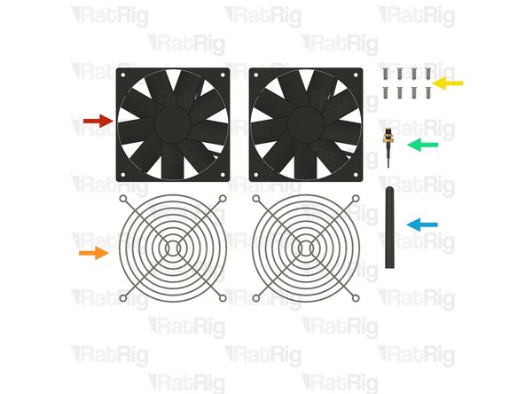
2x Fan - 120mm x 15mm
-
2x Fan Grille - 120mm - Black
-
8x Self Tapping Screw - Plastic Fan - 12mm
-
Prepare the following only if you are building the intermediate Bundle:
-
IPEX to SMA Female WiFi Pigtail
-
SMA 2.4GHz WiFi Antenna
-
-
-
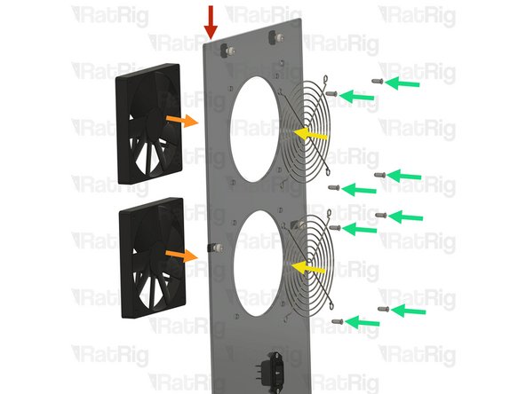
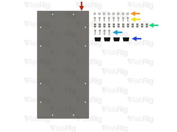
Right panel assembly
-
2x Fan - 120mm x 15mm
-
2x Fan Grille - 120mm - Black
-
8x Self Tapping Screw - Plastic Fan - 12mm
-
Insert the self-tapping screws through the fan grill and the right panel assembly, then thread them into the 120mm fans.
-
Do not overtighten the screws, as this may damage the fan body.
-
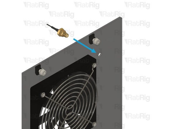
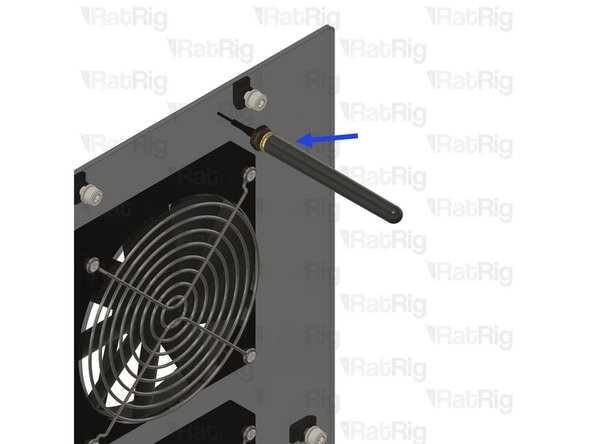
Insert the IPEX to SMA Female WiFi Pigtail into the right panel assembly and secure it with its panel lock nut.
-
Thread the SMA 2.4GHz WiFi Antenna to the previously installed IPEX to SMA female WIFI Pigtail.
-
-
-
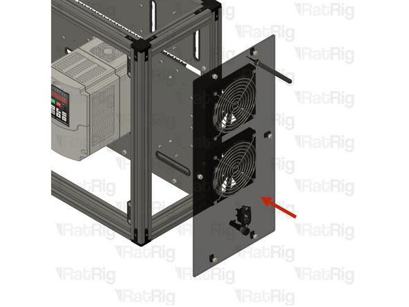
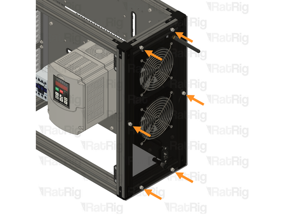
Install the right panel assembly to the frame as shown.
-
Secure the left panel assembly to the frame by fastening the M5 cap head screws.
-
-
-
Rat Rig Universal CNC Electronics Enclosure - bottom
-
8x M5 Washer
-
8x M5x12 Cap Head Screw
-
12x 3030 Drop-in T-Nut - M5
-
M5x16 Cap Head Screw
-
4x Rubber foot with metal insert - Heavy Duty
-
-
-
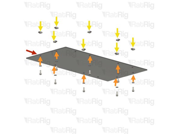
Rat Rig Universal CNC Electronics Enclosure - bottom
-
(8x) M5x12 Cap Head Screw + M5 Washer
-
8x 3030 Drop-in T-Nut - M5
-
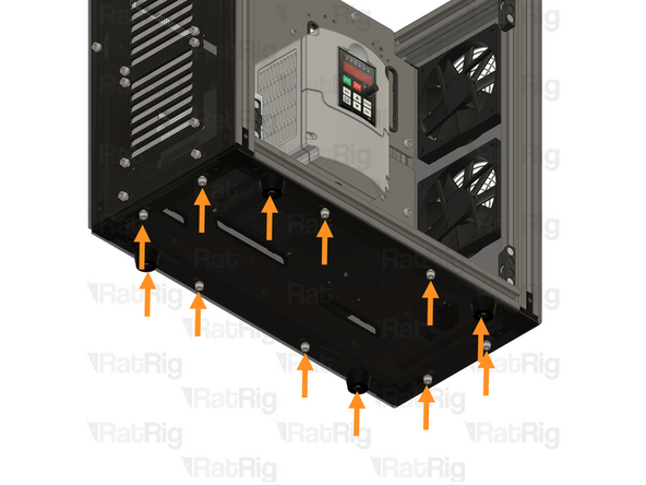
Insert an M5x12 Cap Head Screw into each marked hole on the right panel and loosely tighten a M5 drop-in T-nut to each screw.
-
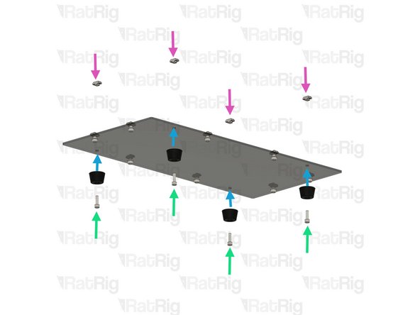
4x M5x16 Cap Head Screw
-
4x Rubber foot with metal insert - Heavy Duty
-
4x 3030 Drop-in T-Nut - M5
-
Insert the M5x16 Cap Head Screws into the Rubber foot and through the panel, then loosely tighten the Drop-in T-nuts.
-
-
-
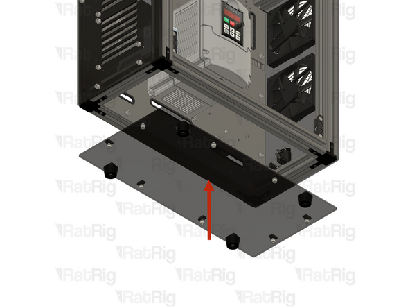
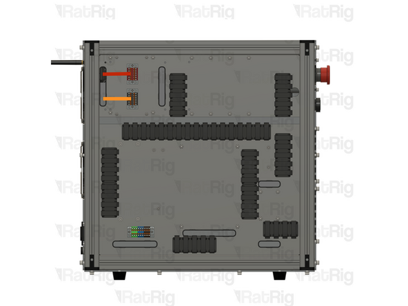
Install the bottom panel assembly to the frame as shown.
-
Secure the left panel assembly to the frame by fastening the M5 cap head screws.
-
-
-
You will need to cut the JST connector on the Fans - 120mm x 15mm, as well as crimp a ferrule to each wire.
-
Insert both Red wires from the fans into the +24V RED PTFix terminal.
-
Insert both Black wires from the fans into the -24V Black PTFix terminal.
-