
Introduction
Please note: This guide is based upon building a 1000x1000 StrongHold PRO.
Measurements for the 1000x1500 and 1500x1500 machine sizes are provided in the relevant steps.
It is strongly recommended to assemble the X-axis gantry on a known flat surface (such as a solid table, work surface or similar). Assembling on a carpeted floor, or other non-flat surface, can cause the finished gantry to not be square. This can cause issues with quality and performance.
-
-
2x 1216mm 4080 Extrusion (1716mm for the StrongHold PRO 1500x1500)
-
1x 1216mm 40120 Extrusion (1716mm for the StrongHold PRO 1500x1500)
-
14x M12 Washer
-
14x M12x45 Cap Head Screw
-
1x Rat Rig StrongHold PRO CNC - XY Joiner Plate Left
-
1x Rat Rig StrongHold PRO CNC - XY Joiner Plate Right
-
4x sh_pro_hg25r_end_spacer Printed Part
-
4x 4040 Extruded Corner Assembly (For the gantry)
-
-
-
1216mm 4080 Extrusion
-
1716mm for the StrongHold PRO 1500x1500
-
1216mm 40120 Extrusion
-
1716mm for the StrongHold PRO 1500x1500
-
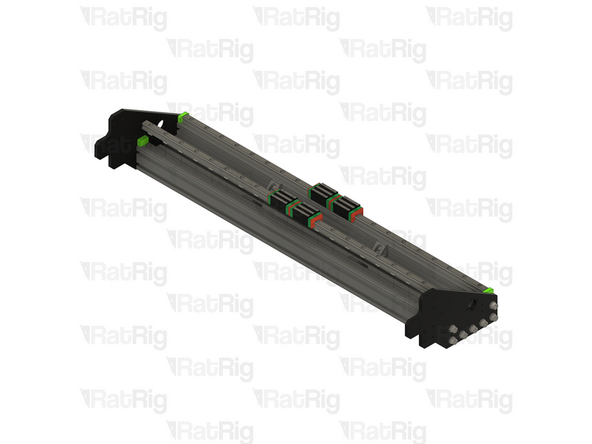
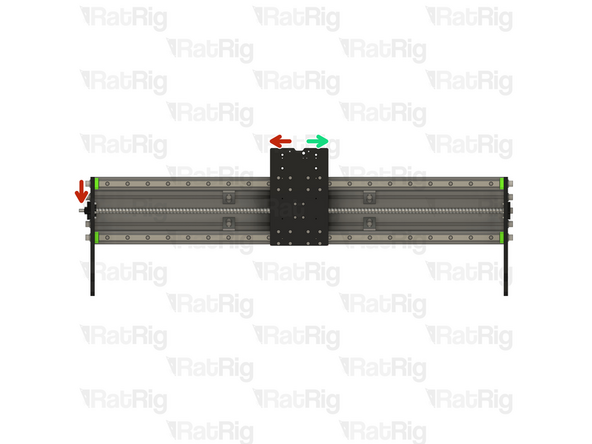
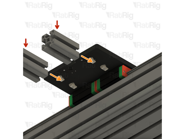
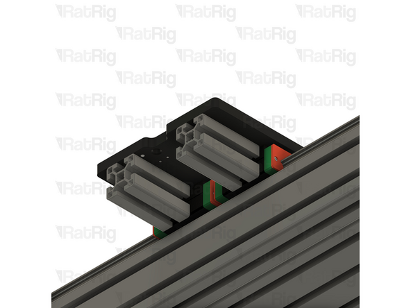
Position the three extrusions as shown to form a "C" shape as shown
-
-
-
4040 Extruded Corner Assembly
-
Slide each 4040 corner assembly in to the inner channel as shown
-
Position the 4040 corner assemblies based upon the following measurements:
-
1000x1000 or 1000x1500:
-
380mm
-
1500x1500:
-
550mm
-
Do not tighten the corner assemblies at this point, this will be done after squaring the assembly
-
-
-
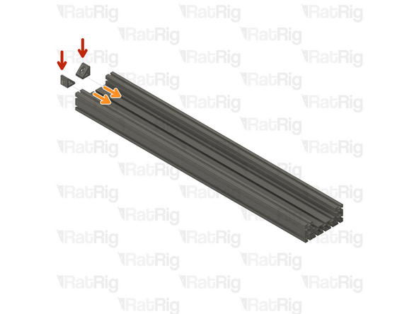
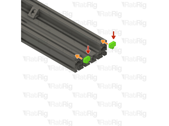
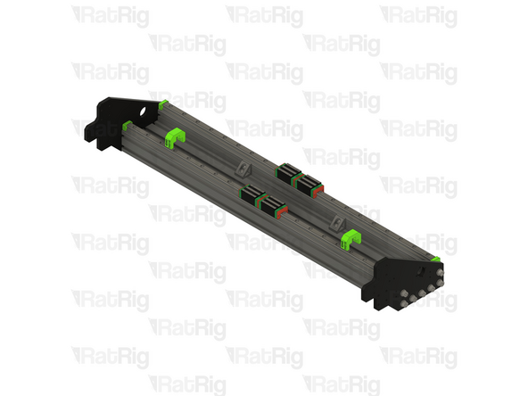
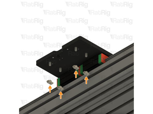
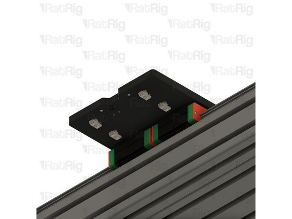
sh_pro_hg25r_end_spacer Printed Part
-
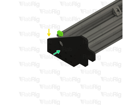
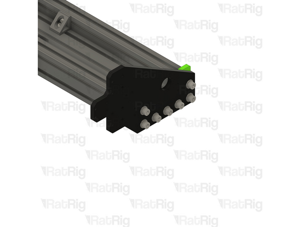
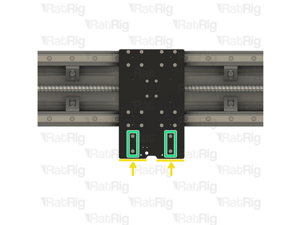
Insert two sh_pro_hg25r_end_spacer printed parts in to the 4080 extrusions as shown
-
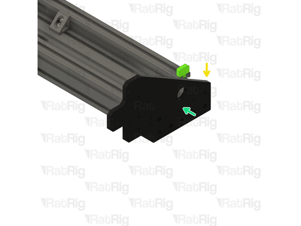
Rat Rig StrongHold PRO CNC - XY Joiner Plate Left
-
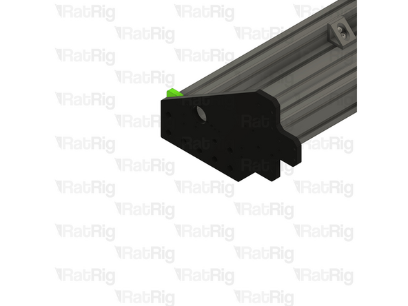
Verify you are installing the correct plate on the left side. The left plate has additional holes not found on the right one.
-
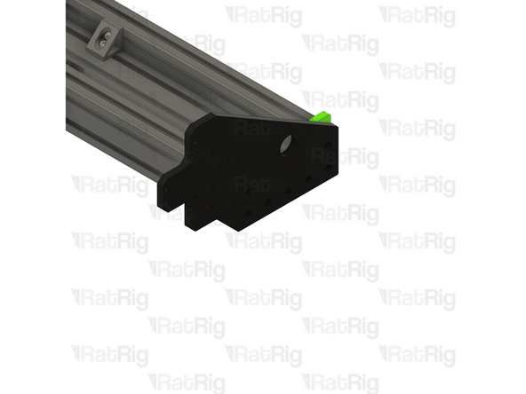
Align the XY Joiner plate with the end of the gantry assembly
-
-
-
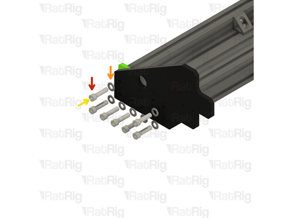
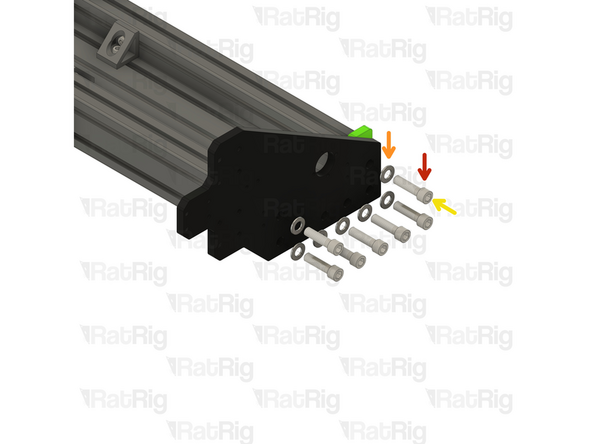
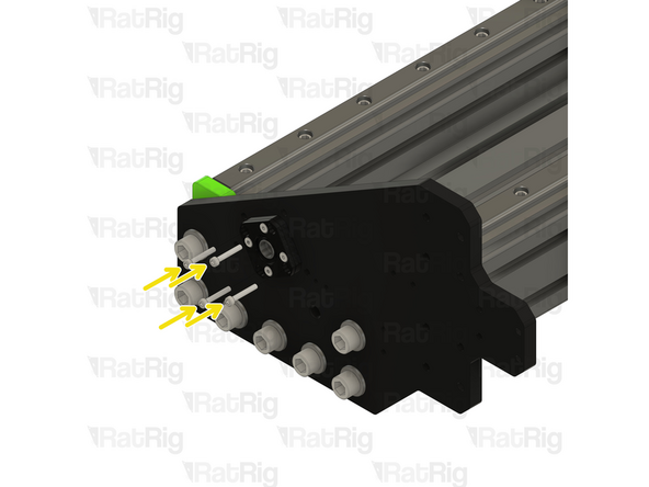
M12x45 Cap Head Screw
-
M12 Washer
-
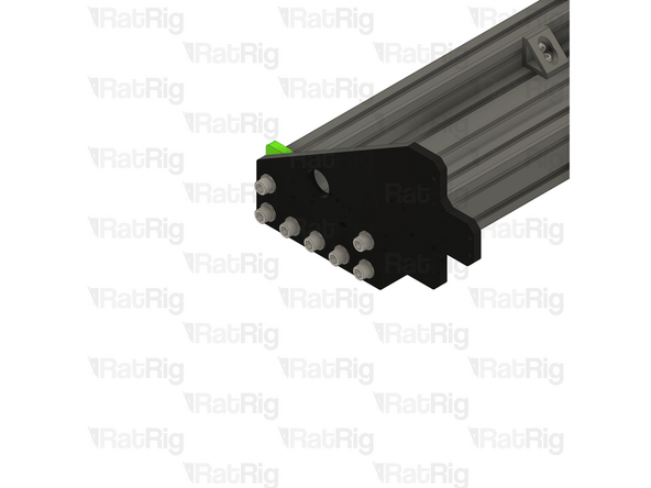
Place an M12 washer on to each M12x45 cap head screw and loosely screw them through the plate and in to the extrusion
-
Do not fully tighten any of the M12 screws at this point
-
-
-
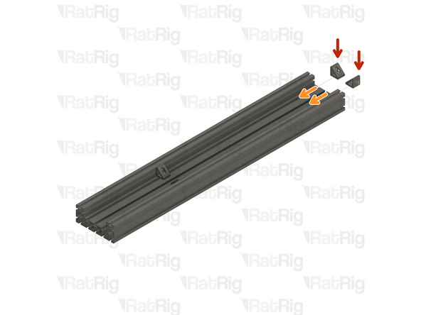
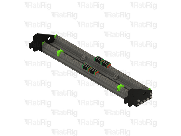
sh_pro_hg25r_end_spacer Printed Part
-
Insert two sh_pro_hg25r_end_spacer printed parts in to the 4080 extrusions as shown
-
Rat Rig StrongHold PRO CNC - XY Joiner Plate Right
-
Align the XY Joiner plate with the end of the gantry assembly
-
-
-
M12x45 Cap Head Screw
-
M12 Washer
-
Place an M12 washer on to each M12x45 cap head screw and loosely screw them through the plate and in to the extrusion
-
Do not fully tighten any of the M12 screws at this point
-
-
-
Before continuing with the assembly, the gantry must be squared and all screws full tightened
-
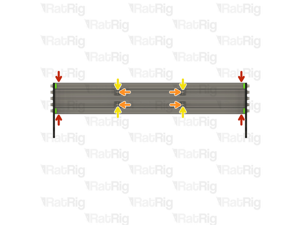
Ensure the three extrusions are pressed together with no gaps. If clamps are available, the extrusions can be optionally clamped together for the remainder of this step. If using clamps, make sure they are positioned as low as possible. Do not deform the "C" shape of the extrusions!
-
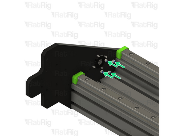
Tighten the four marked M8x16 screws in the extruded brackets to secure them to the rear 40120 extrusion. Check that the measurements mentioned in Step 3 are maintained
-
Verify there are no gaps between the extrusions, and that the extrusion ends are aligned
-
Fully tighten the remaining four M8x16 screws in the extruded brackets
-
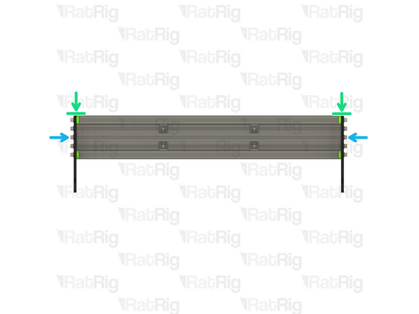
Using an engineers square, or a flat edge, check that the side plates are flush with the extrusions at the top of the gantry
-
Fully tighten all fourteen M12x45 screws on both ends of the gantry to secure everything together
-
Verify that all parts of the X-axis gantry assembly are still correctly aligned and adjust as necessary
-
-
-
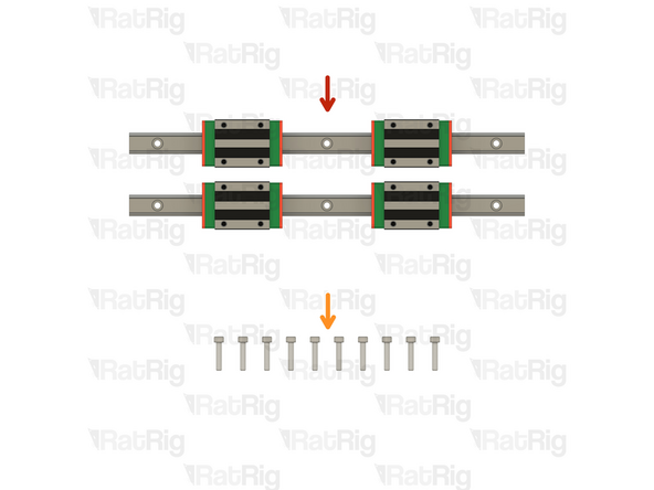
2x 1190mm HG25 Linear Rail with 2x Carriages
-
2x 1690mm for a 1500x1500 machine
-
40x M6x25 Cap Head Screw
-
56x for a 1500x1500 machine
-
40x 4040 Drop-in T-Nut - M6
-
56x for a 1500x1500 machine
-
2x align_4080_hg25 Printed Part
-
-
-
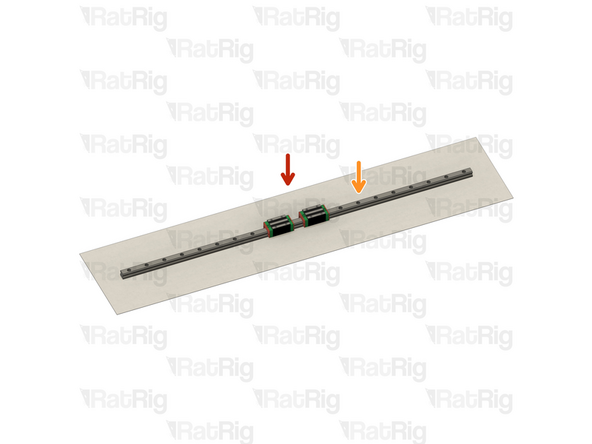
The linear rails are supplied with a protective oil coating on them. It is strongly recommended to prepare your work surface with paper towels and to wear disposable gloves.
-
Paper Towels
-
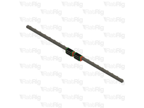
Linear Rail
-
Carefully open one end of the linear rail packaging and remove the rail. Place the rail upon the paper towels and dispose of the packaging
-
The oil on the rails protects them from rusting. Make sure not to remove all of the original oil during preparation.
-
The linear rail carriages are not interchangeable. Do not try to use a carriage on a different linear rail than the one it was supplied with.
-
-
-
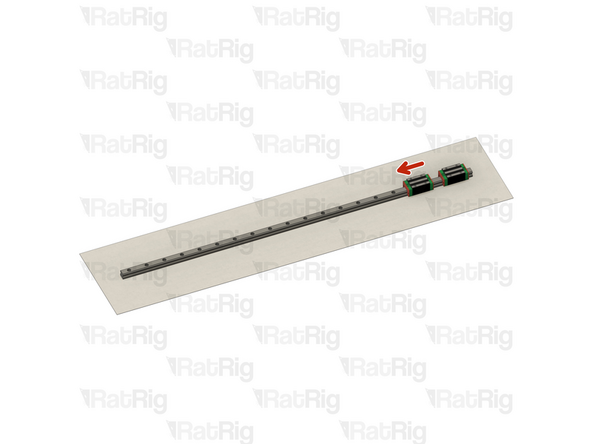
With the rail still on the absorbent paper towels, carefully and slowly move the carriage from one end of the rail to the other
-
Both carriages should move smoothly over the entire length of the rail
-
Small changes in resistance are normal, but the carriage becoming very hard to push, or binding completely are not
-
Repeat the previous test whilst applying a small amount of force downwards on the carriage
-
The carriage will likely travel more smoothly when applying a downwards force, this is normal
-
Repeat the process to check the second carriage on the rail
-
If the carriage does not move smoothly, or binds completely, refer to the Linear Rail Troubleshooting Guide
-
-
-
Do not allow the linear rail carriages to leave the end of the rail at any point
-
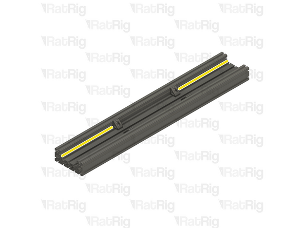
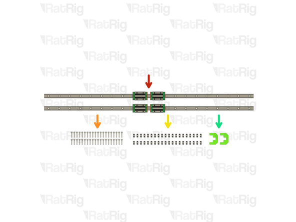
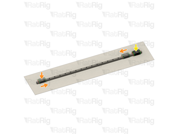
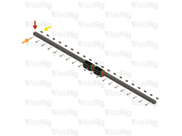
HG25 Linear Rail
-
Insert an M6x25 cap head screw in each of the holes on the linear rail
-
Loosely thread a 4040 T-Nut on to each of the M6x25 screws
-
Repeat these instructions for the second linear rail
-
-
-
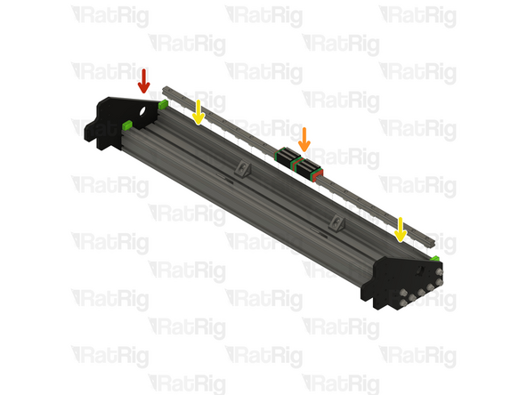
StrongHold PRO X-Axis Gantry Assembly from Step 8
-
HG25 Linear Rail Assembly from Step 12
-
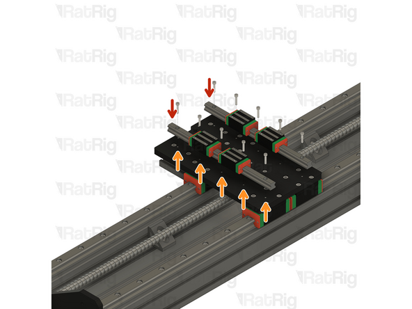
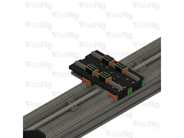
Insert the linear rail into the slot of the 4080 extrusion, between the 3D printed spacers
-
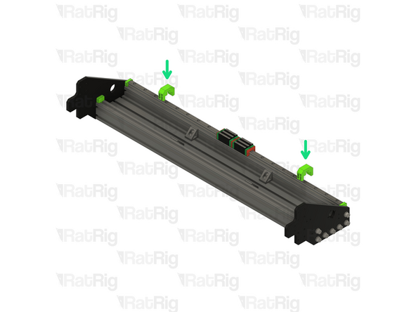
Install the two HG25 4080 alignment tools as shown, this will make sure the linear rail is positioned correctly
-
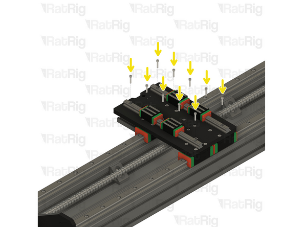
Tighten every other M6x25 screw, starting from one end
-
Tighten the remaining M6x25 screws, starting from the same end as before
-
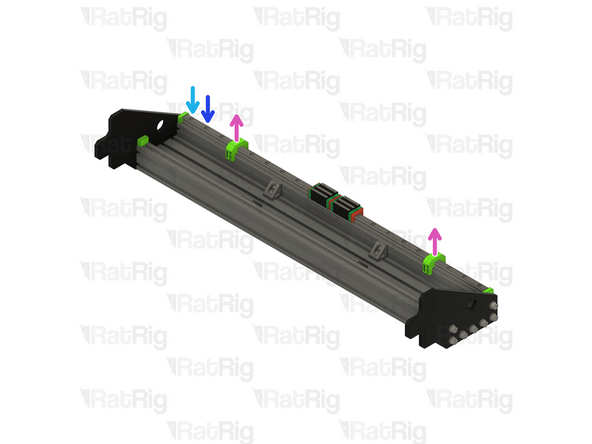
Remove the HG25 40120 alignment tools
-
-
-
Repeat the instructions in the previous step to install the second HG25 linear rail to the X-axis gantry assembly
-
-
-
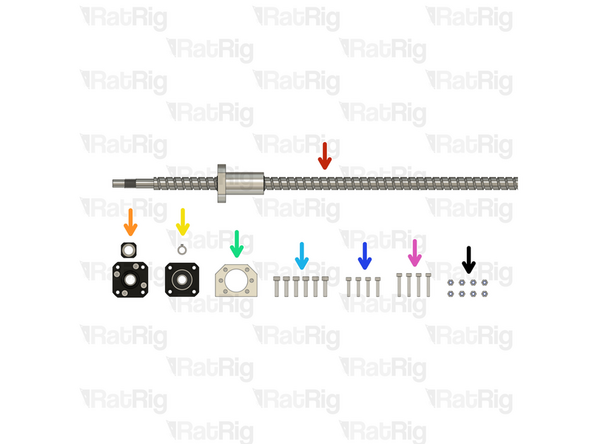
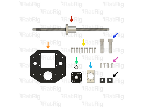
1x 1280mm 1610 Ball Screw (1780mm for a 1500x1500 machine)
-
1x FK12 Ball Screw Mount & Ball Screw lock nut (Packaged with the FK12 mount)
-
1x FF12 Ball Screw Mount & Circlip (Packaged with the FF12 mount)
-
1x 16mm Ball Screw Block
-
6x M5x20 Cap Head Screw
-
4x M4x20 Cap Head Screw
-
4x M4x25 Cap Head Screw
-
8x M4 Nylon Locking Hex Nut
-
-
-
1280mm 1610 Ball Screw (1780mm for a 1500x1500 machine)
-
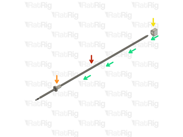
Unpack and remove all protective packaging from the ball screw
-
Ball screw nut
-
Do not allow the ball screw nut to reach the end of the ball screw
-
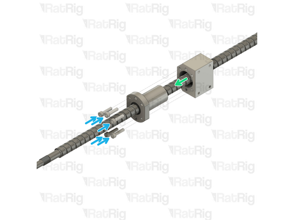
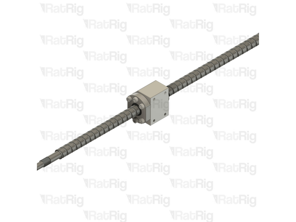
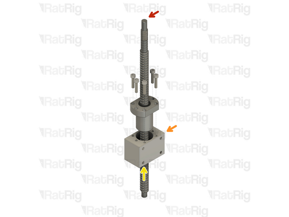
16mm Ball Screw Block
-
Install the ball screw block onto the ball screw nut as shown
-
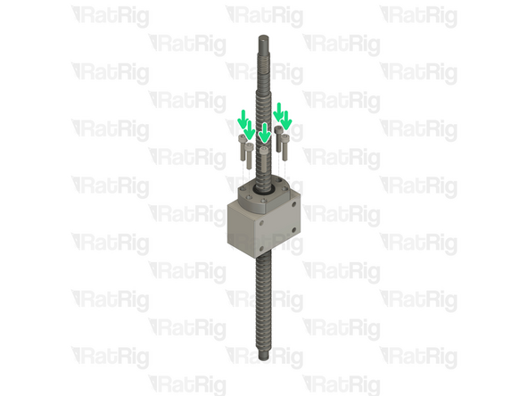
6x M5x20 Cap Head Screw
-
Install an M5x20 screw through each hole in the ball screw nut and into the ball screw block. Fully tighten each screw
-
-
-
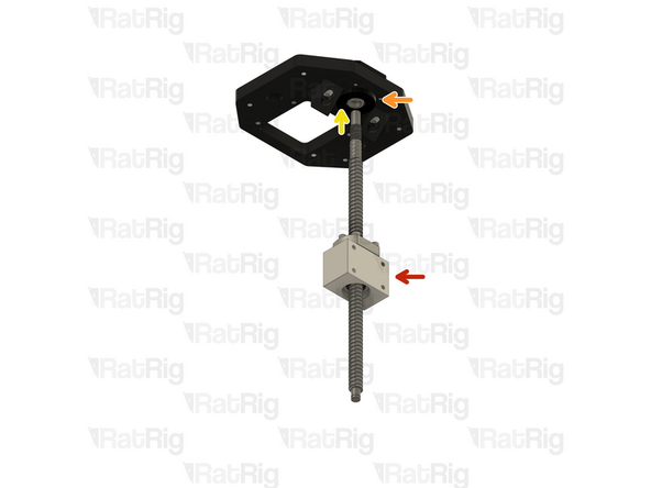
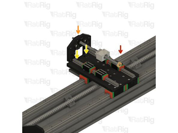
X-Axis Gantry Assembly - Left Side
-
FK12 Ball Screw Mount
-
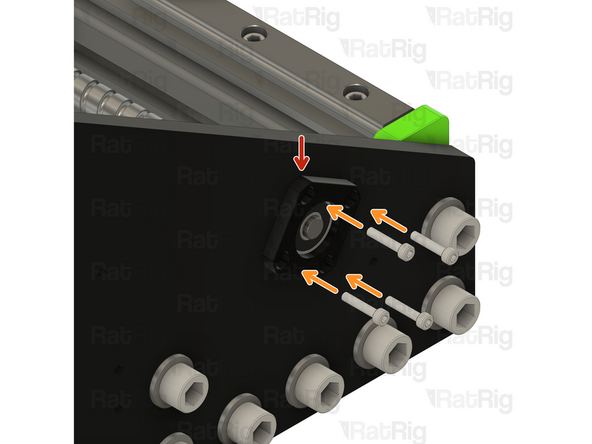
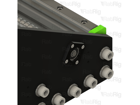
Insert the FK12 ball screw mount in to the left plate as shown
-
M4x25 Cap Head Screw
-
Insert an M4x25 screw through each of the four holes in the FK12 mount and through the left plate
-
M4 Nylon Locking Hex Nut
-
Install an M4 locking hex nut onto each M4x25 screw and tighten fully
-
-
-
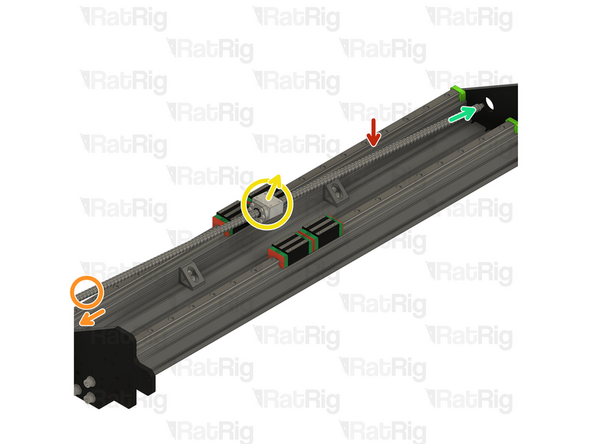
Position the ball screw assembly (from Step 16) so that:
-
The end with the thread faces towards the FK12 mount
-
The side of the ball screw block with the screw holes faces away from the X-axis gantry assembly
-
Carefully feed the non-threaded end of the ball screw through the open hole in the right plate on the gantry
-
Align the threaded end of the ball screw with the hole in the FK12 mount
-
Whilst supporting the full length of the ball screw, insert the threaded end through the hole in the FK12 mount
-
The ball screw is a precision fit into the FK12 mount. Do not force the ball screw in to the mount. When correctly aligned, it should slide in with little effort
-
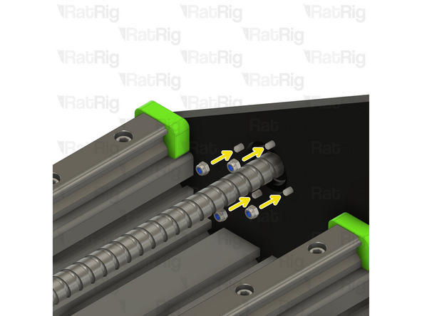
Install the FF12 ball screw mount onto the free end of the ball screw and into the opening on the right plate
-
-
-
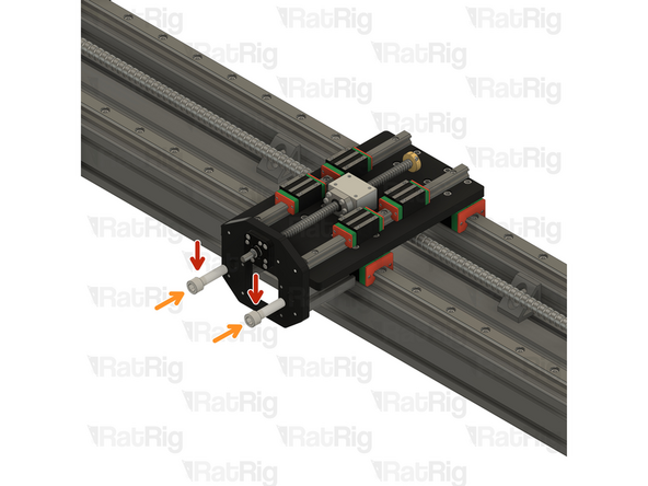
FF12 Ball Screw Mount
-
M4x20 Cap Head Screw
-
Insert an M4x20 screw through each of the four holes in the FF12 mount and through the idler plate
-
M4 Nylon Locking Hex Nut
-
Install an M4 locking hex nut onto each M4x20 screw and tighten fully
-
-
-
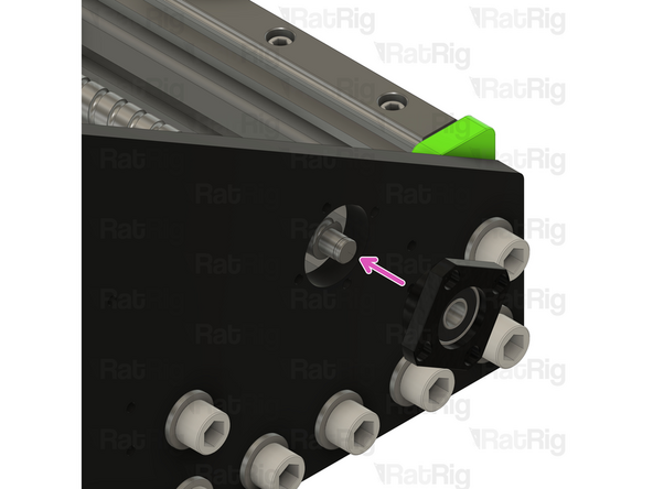
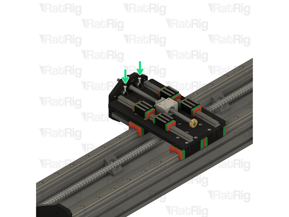
FK12 Ball Screw Mount
-
Ball Screw Lock Nut
-
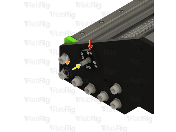
Fasten the ball screw lock nut on to the exposed end of the ball screw as shown
-
When the ball screw lock nut is fully tightened, use a 2mm hex key to tighten the grub screw within the lock nut. This will prevent the lock nut from loosening
-
-
-
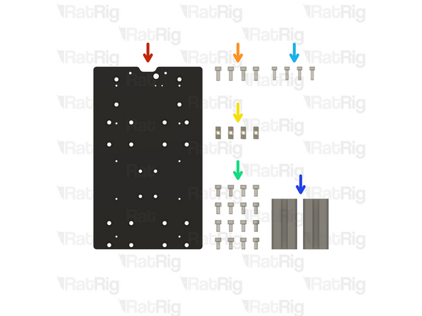
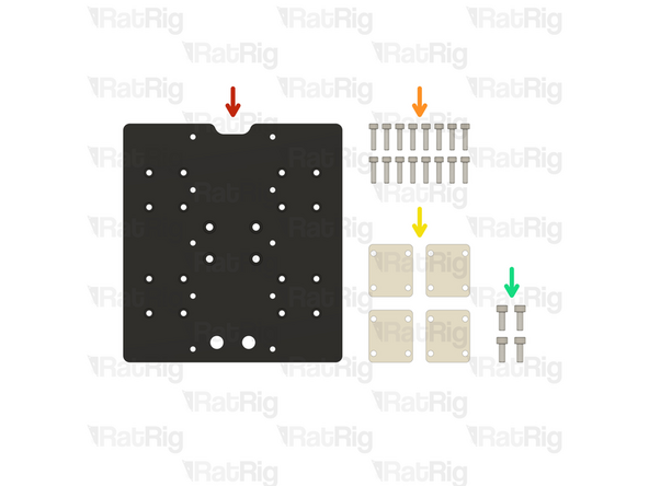
1x Rat Rig StrongHold PRO CNC - XZ Joiner Plate
-
4x M6x16 Cap Head Screw
-
4x 4040 Drop-in T-Nut - M6
-
16x M6x12 Cap Head Screw
-
4x M5x16 Cap Head Screw
-
2x 80mm 4040 Extrusion
-
-
-
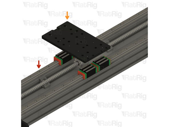
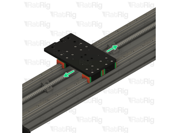
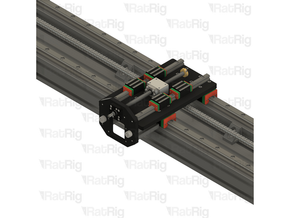
X-Axis Gantry Assembly
-
Rat Rig StrongHold PRO CNC - XZ Joiner Plate
-
Position the HG25 linear rail blocks so that the holes align with those on the XZ joiner plate
-
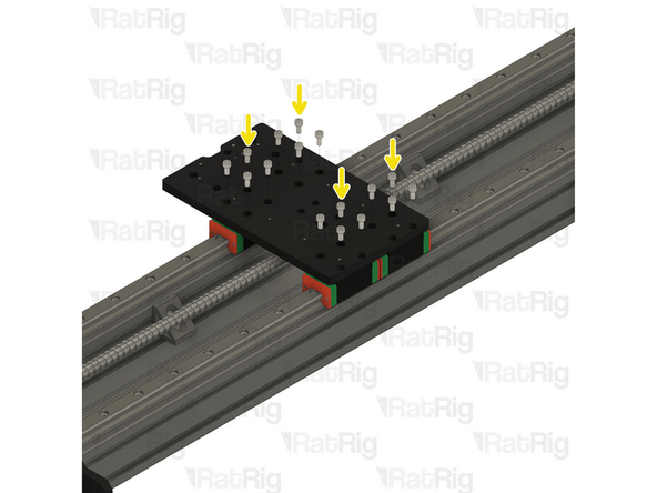
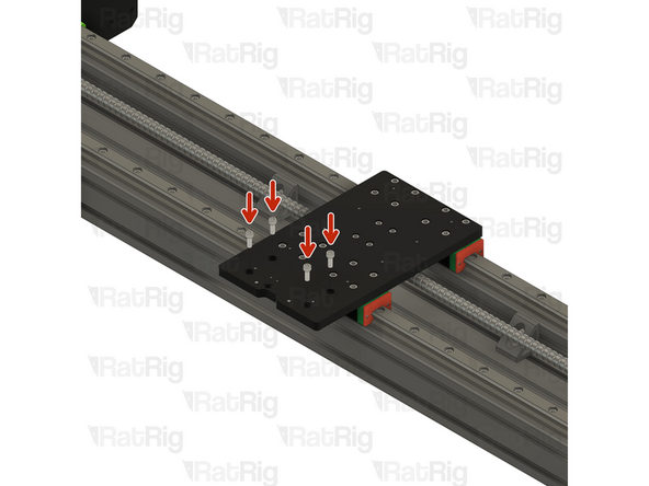
M6x12 Cap Head Screw
-
Install an M6x12 screw through each hole in the plate, and in to the HG25 linear rail carriage below
-
Before fully tightening the M6x12 screws, check that the X-axis moves over its entire length without binding
-
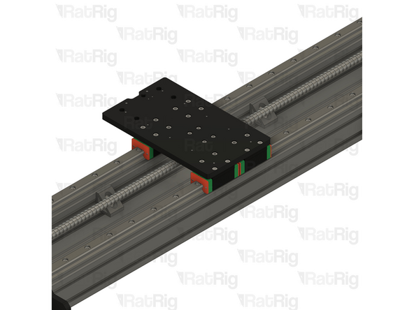
Tighten each screw slightly and then re-test the smoothness of the X-axis. Repeat this until all sixteen screws are fully tightened, securing the plate
-
If the X-axis binds or becomes tight, check that the lower rail is aligned correctly. Loosening the screws securing the lower rail to the 4080 extrusion and using the X-axis to align the lower rail can help.
-
-
-
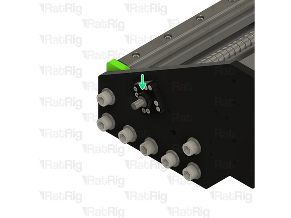
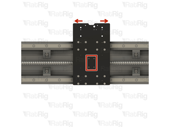
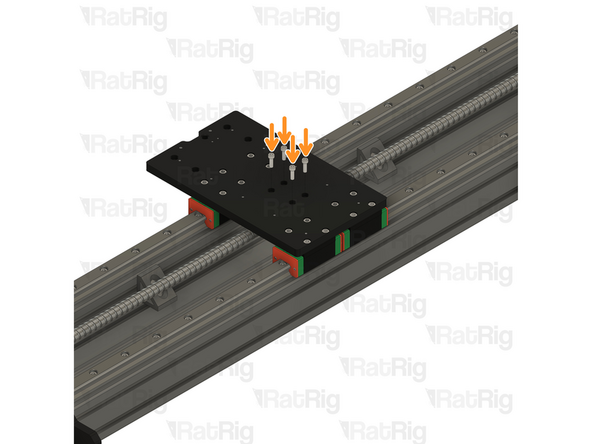
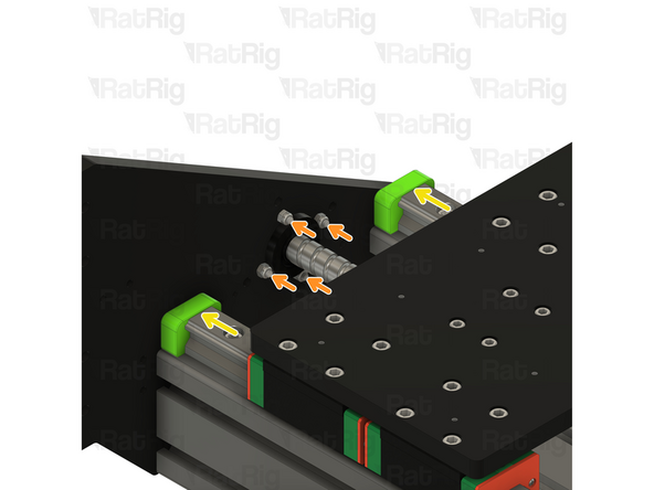
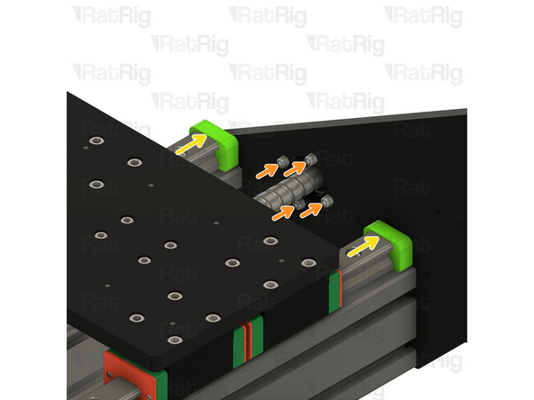
Align the X-axis so that the screw holes in the ball screw block are visible through the marked holes in the plate
-
M5x16 Cap Head Screw
-
Install each of the four M5x16 screws though the plate and secure them in to the ball screw block
-
-
-
It is important to verify that the X-axis ball screw is fully aligned before continuing
-
Move the X-axis all the way to the left side by rotating the ball screw
-
If the X-axis becomes tight and difficult to move as it approaches the left end, do the following:
-
Loosen all four of the M4x25 screws securing the FK12 mount in place
-
Move the X-axis fully to the end
-
Re-tighten all four of the M4x25 screws on the FK12 mount
-
Move the X-axis all the way to the right side by rotating the ball screw
-
If the X-axis becomes tight and difficult to move as it approaches the right end, repeat the above instructions to adjust the FF12 mount
-
-
-
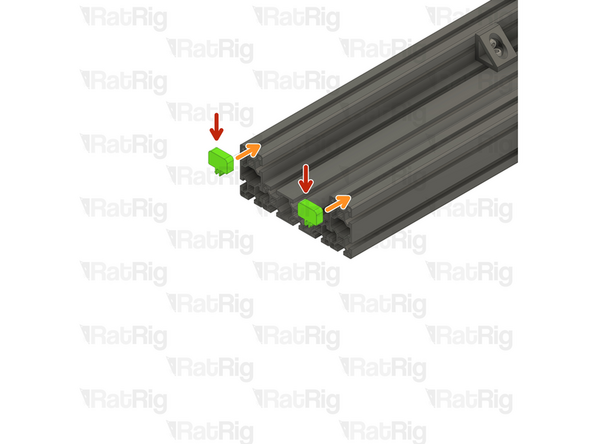
M6x16 Cap Head Screw
-
4040 Drop-in T-Nut - M6
-
Loosely thread the 4040 T-Nuts on to the M6x16 screws. Do not tighten them at this point.
-
-
-
80mm 4040 Extrusion
-
Position each 4040 extrusion as shown, ensuring that the tapped end of the extrusion faces away from the gantry
-
Check that the end of each extrusion is flush with the XZ joiner plate
-
Tighten each of the M6x16 screws to secure the extrusions to the XZ joiner plate
-
-
-
2x 280mm HG15 Linear Rail with 2x Carriages
-
10x M4x20 Cap Head Screw
-
Unpack and test the HG15 linear rails as previously instructed in Steps 9 & 10
-
The linear rail carriages are not interchangeable. Do not try to use a carriage on a different linear rail than the one it was supplied with.
-
-
-
HG15 Linear Rail
-
Align the holes in the linear rail with the screw holes on the XZ joiner plate
-
M4x20 Cap Head Screw
-
Insert a screw into each hole on the linear rail and fully tighten them in to the XZ joiner plate
-
-
-
1x 300mm 1204 Ball Screw
-
1x Rat Rig StrongHold PRO CNC - Z Top Plate
-
10x M4x18 Cap Head Screw
-
1x FK10 Ball Screw Mount & Ball Screw lock nut (Packaged with the FK10 mount)
-
1x 12mm Ball Screw Block
-
2x M12x45 Cap Head Screw
-
4x M5x16 Button Head Screw
-
2x 90 Degree Corner Connector
-
-
-
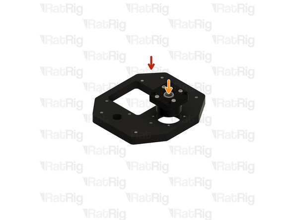
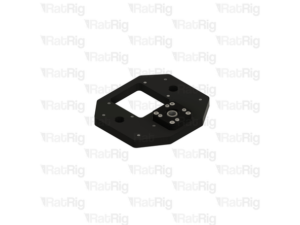
Rat Rig StrongHold PRO CNC - Z Top Plate
-
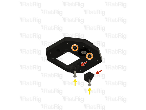
FK10 Ball Screw Mount
-
Position the FK10 mount in to the Z top plate as shown, aligning the holes with the threaded holes in the plate
-
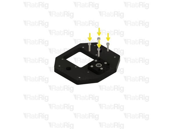
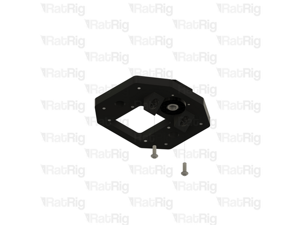
M4x18 Cap Head Screw
-
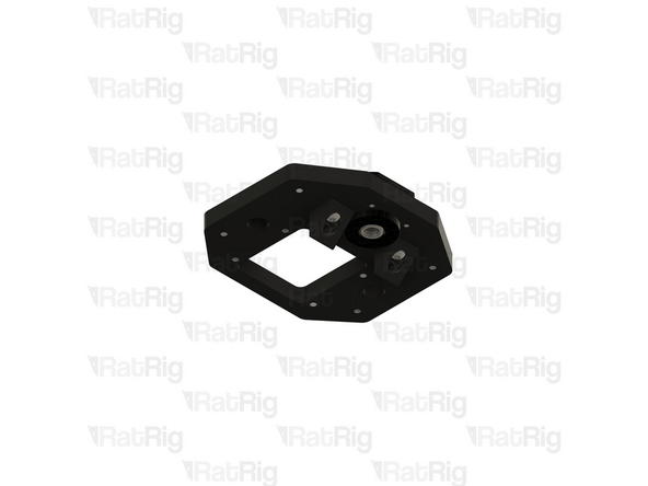
Insert and tighten all four M4x18 screws through the FK10 mount and in to the plate
-
Do not over tighten the M4x18 screws as doing so can damage the screw threads in the aluminium
-
-
-
90 Degree Corner Connector
-
Position each 90 degree corner connector with the marked hole, in the orientation shown
-
M5x16 Button Head Screw
-
Secure each 90 degree corner connector with an M5x16 screw
-
Do not over tighten the M5x16 screws as doing so can damage the screw threads in the aluminium
-
-
-
300mm 1204 Ball Screw
-
12mm Ball Screw Block
-
Install the ball screw block onto the ball screw nut as shown
-
6x M4x18 Cap Head Screw
-
Install an M4x18 screw through each hole in the ball screw nut and into the ball screw block. Fully tighten each screw
-
-
-
300mm 1204 Ball Screw Assembly
-
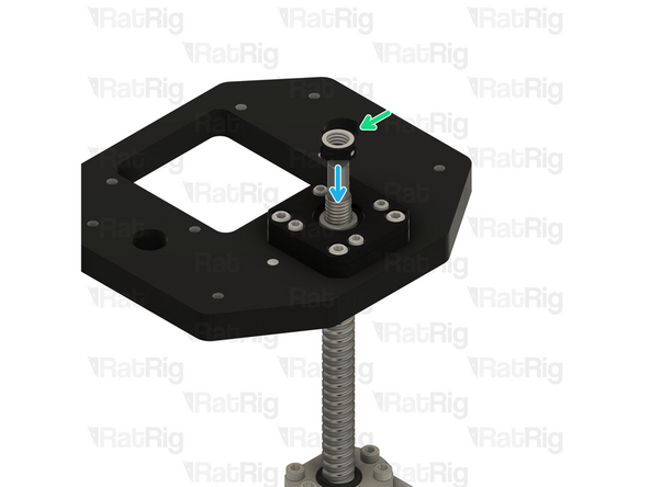
FK10 Ball Screw Mount
-
Insert the threaded end of the ball screw through the hole in the FK10 mount
-
The ball screw is a precision fit into the FK10 mount. Do not force the ball screw in to the mount. When correctly aligned, it should slide in with little effort
-
Ball Screw Lock Nut
-
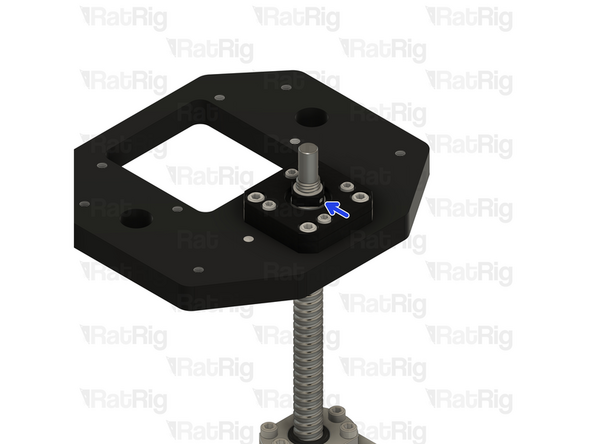
Fasten the ball screw lock nut on to the exposed end of the ball screw as shown
-
When the ball screw lock nut is fully tightened, use a 2mm hex key to tighten the grub screw within the lock nut. This will prevent the lock nut from loosening
-
From this point forward, make sure that the ball screw nut remains near the middle of the ball screw. Allowing the ball screw nut to reach the end of the ball screw will cause permanent damage to the ball screw
-
-
-
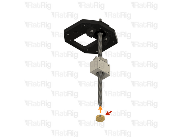
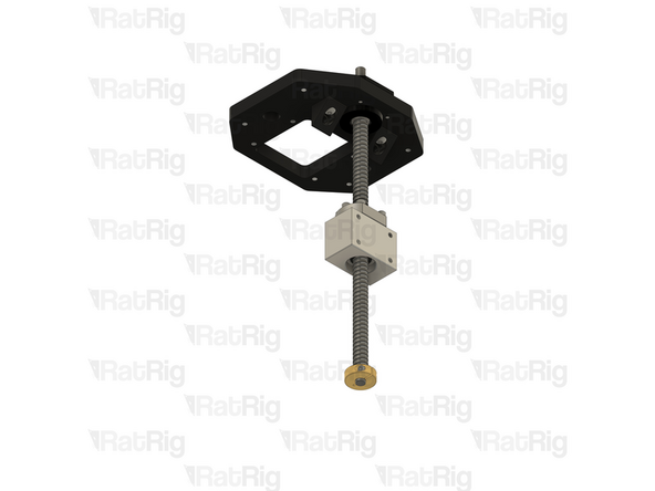
8mm Clamping Lock Collar
-
Install the lock collar on to the end of the ball screw as shown
-
M3x12 Cap Head Screw
-
Fully tighten the M3 screw in the lock collar to secure it to the ball screw
-
-
-
StrongHold PRO X-Axis Gantry Assembly from Step 27
-
StrongHold PRO Z-axis Transmission Assembly from Step 33
-
Position the Z-axis transmission assembly as shown, aligning the 90 degree corner connectors with the indicated holes
-
M5x16 Button Head Screw
-
Fasten each 90 degree corner connector to the XZ joiner plate with an M5x16 screw
-
Do not over tighten the M5x16 screws as doing so can damage the screw threads in the aluminium
-
-
-
M12x45 Cap Head Screw
-
Insert one M12x45 screw through each hole in the Z top plate and secure in to the 4040 extrusion
-
Fully tighten both M12x45 screws
-
Check all four previously installed M5x16 button head screws are fully tightened as well
-
-
-
1x Rat Rig StrongHold PRO CNC - Z-Axis Plate
-
16x M4x16 Cap Head Screw
-
4x Rat Rig StrongHold PRO CNC - HG15 Spacer
-
4x M5x14 Cap Head Screw
-
-
-
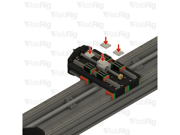
Rat Rig StrongHold PRO CNC - HG15 Spacer
-
Place one spacer on top of each HG15 linear rail carriage
-
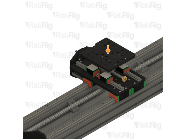
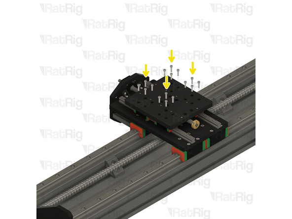
Rat Rig StrongHold PRO CNC - Z-Axis Plate
-
Place the Z-axis plate on top of the spacers and adjust the carriage positions so that all 16 holes are aligned
-
M4x16 Cap Head Screw
-
Insert each M4x16 screw through the Z-axis plate, the HG15 spacer, and thread them in to the linear rail carriage
-
Fully tighten all the M4x16 screws
-
-
-
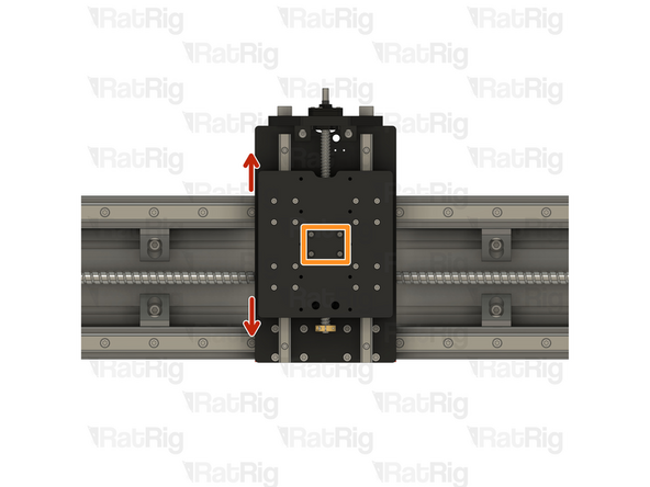
Before proceeding, check that the Z-axis moves smoothly
-
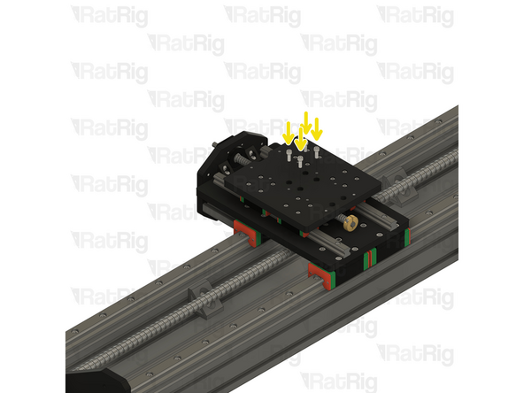
Align the marked holes in the Z-axis plate with the holes in the 12mm ball screw nut block below
-
M5x14 Cap Head Screw
-
Insert each M5x14 screw through the Z-axis plate, and thread them in to the ball screw block
-
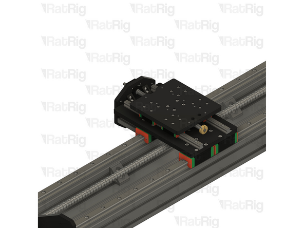
Fully tighten all four M5x14 screws
-
-
-
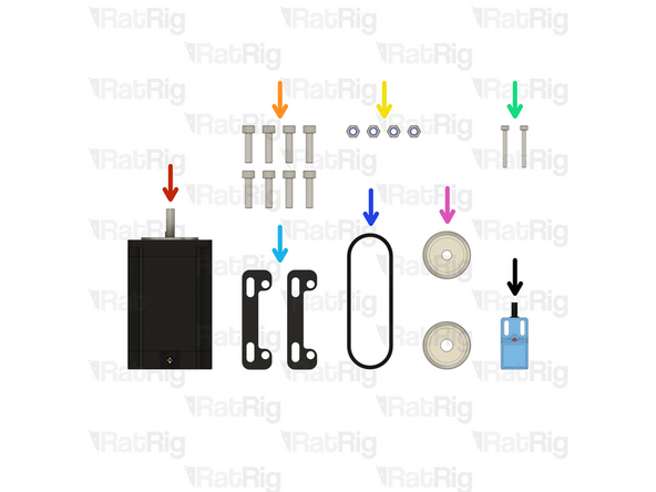
1x NEMA23 Stepper Motor
-
8x M5x20 Cap Head Screw
-
4x M5 Nylon Locking Hex Nut
-
2x M3x25 Cap Head Screw
-
2x Rat Rig StrongHold PRO CNC - NEMA23 Plate
-
1x HTD3M 180mm Belt Loop
-
2x HTD3M Drive Pulley (1x 6.35mm Bore & 1x 8mm Bore)
-
1x SN04-N2 Proximity Sensor
-
-
-
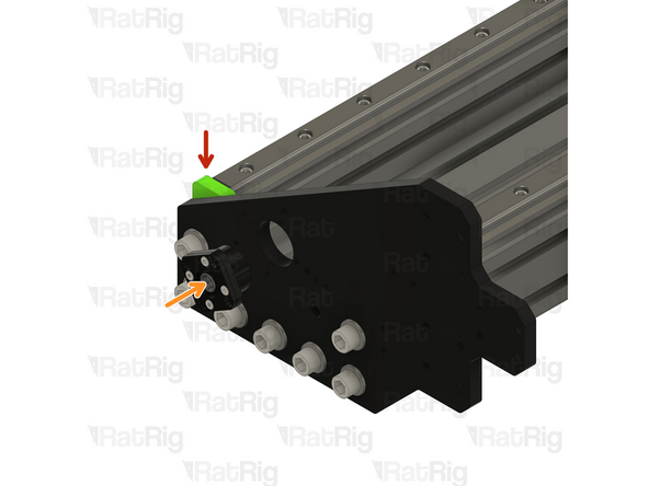
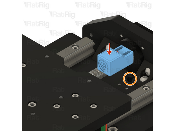
SN04-N2 Proximity Sensor
-
Pass the end of the proximity sensor cable through the marked hole
-
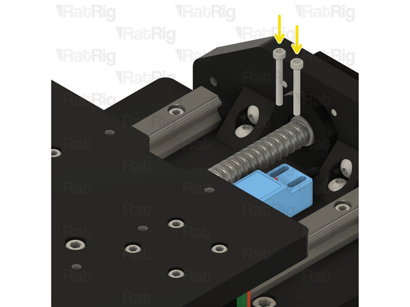
M3x25 Cap Head Screw
-
Insert each M3x25 screw through the proximity sensor and thread them in to the M3 holes on the XZ joiner plate
-
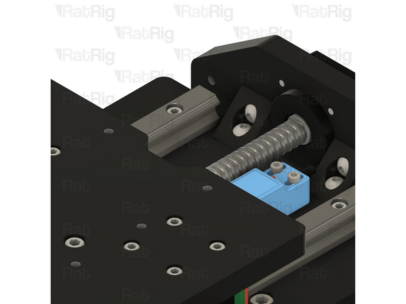
Do not over tighten the M3x25 screws as doing so can damage the proximity sensor or the screw threads in the aluminium
-
-
-
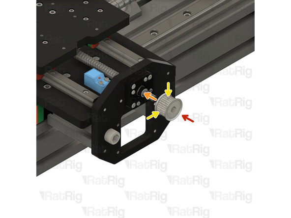
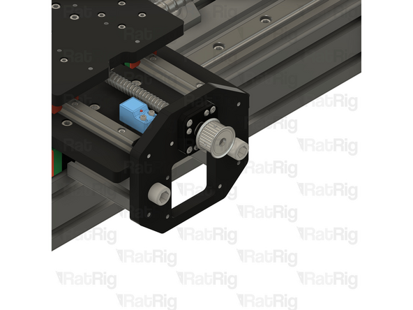
HTD3M Drive Pulley - 8mm Bore
-
Install the HTD3M drive pulley on to the exposed end of the 1204 ball screw
-
2.5mm Grub Screw
-
If the drive pulley does not easily slide on to the ball screw, check that both grub screws on the pulley are clear of the bore
-
Tighten both 2.5mm grub screws to secure the drive pulley to the ball screw
-
-
-
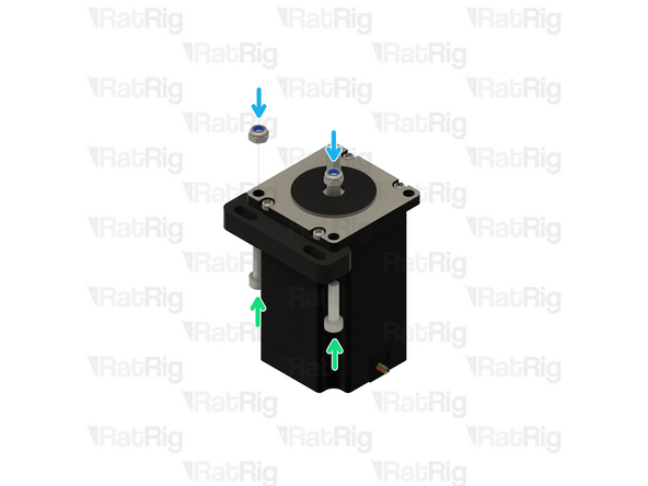
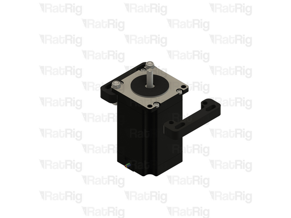
NEMA23 Stepper Motor
-
Pay attention to the orientation of the stepper motor wiring / connector
-
Rat Rig StrongHold PRO CNC - NEMA23 Plate
-
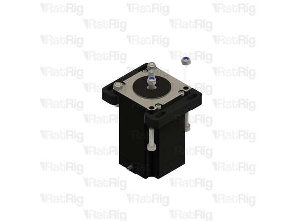
M5x20 Cap Head Screw
-
M5 Nylon Locking Hex Nut
-
Insert each M5x20 screw through the NEMA23 plate, through the NEMA23 stepper motor mounting hole and secure with a locking nut
-
-
-
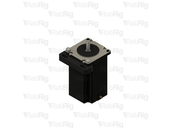
Repeat the instructions in the previous step to install the second NEMA23 plate
-
-
-
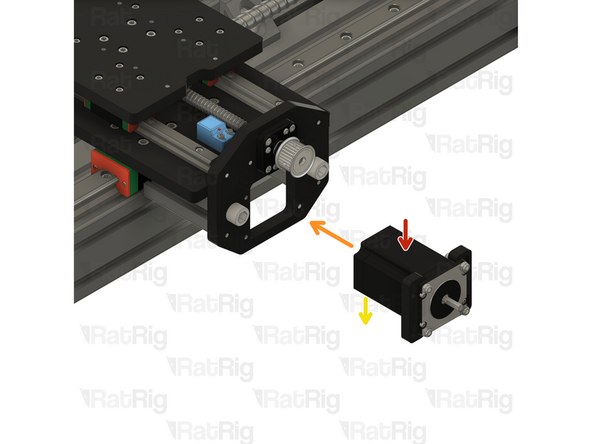
NEMA23 Stepper Assembly
-
Insert the NEMA23 assembly through the hole in the Z top plate as shown
-
Make sure the stepper motor wiring / connector faces towards the back of the X-axis gantry
-
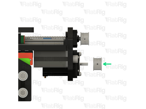
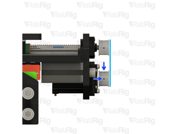
HTD3M Drive Pulley - 6.35mm Bore
-
Align the HTD3M pulley on the NEMA23 shaft so that it is level with the HTD3M pulley on the ball screw
-
If the drive pulley does not easily slide on to the NEMA23 shaft, check that both grub screws on the pulley are clear of the bore
-
Fasten both 2.5mm grub screws to secure the drive pulley to the ball screw
-
Verify the both HTD3M drive pulleys are still aligned. Adjust the position of the NEMA23 pulley if required
-
-
-
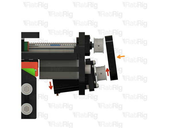
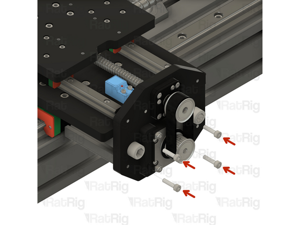
Tilt the NEMA23 stepper assembly as shown
-
HTD3M 180mm drive belt
-
Install the HTD3M drive belt on to both pulleys
-
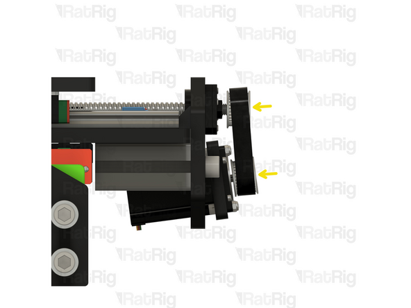
Allow the NEMA23 stepper assembly to return to the original position
-
-
-
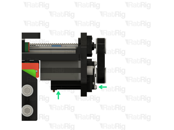
M5x20 Cap Head Screw
-
Insert one M5x20 screw through each hole in the NEMA23 brackets as shown. Do not fully tighten the screws yet
-
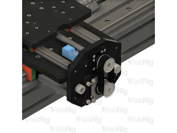
Apply a small amount of downwards force on the NEMA23 assembly to tension the HTD3M drive belt
-
Whilst applying tension to the belt, fully tighten all four M5x20 screws to secure the NEMA23 assembly in place
-
-
-
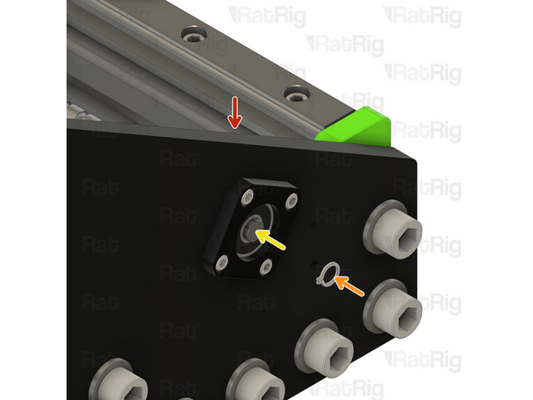
StrongHold PRO X-Axis Gantry - Right Side
-
FF12 Circlip
-
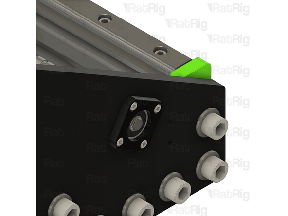
Using a pair of circlip pliers, install the circlip on to the end of the ball screw
-
Make sure the circlip seats fully in the groove on the ball screw
-


Cancel: I did not complete this guide.
2 other people completed this guide.