-
-
The following tools are required for this section of the guide:
-
Allen key / hex wrenches in the following sizes: 2.5mm, 3mm & 5mm
-
Avoid using ball end hex wrenches where possible as they are more prone to damaging the heads of smaller screws
-
The following are recommended for this guide:
-
Paper towels
-
Disposable gloves
-
A light oil, such as 3-in-1 or sewing machine oil
-
-
-
The linear rails are supplied with a protective oil coating on them. It is strongly recommended to prepare your work surface with paper towels and to wear disposable gloves
-
Paper Towels
-
Linear Rail
-
The oil on the rails protects them from rusting. You must either replace this oil after cleaning (as directed below), or make sure not to remove all of the original oil during preparation
-
An easy solution to both protect, and lubricate the rails, is using a light oil such as 3-in-1 or sewing machine oil
-
Apply a small amount of oil to a paper towel and then apply the oil to the rail by wiping it with the oiled paper towel. This may be done prior to, or after the installation of the linear rails
-
Do not remove the plastic stops installed in the ends of the linear rail at this point as they prevent the carriage from leaving the rail
-
More advanced users may wish to fully grease the rails & carriage with a specialised bearing lubricant. It is important to use the correct grade and make sure there are no additives such as PTFE, graphite, molybdenum disulfide, etc. The recommended grade of grease is EP00 or EP000 as these lubricate well, without being too viscous
-
-
-
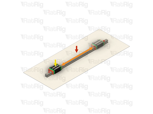
With the linear rail still on the absorbent paper towels, carefully and slowly move the carriage from one end of the rail to the other
-
The carriage should move smoothly over the entire length of the rail
-
Small changes in resistance are normal, but the carriage becoming much harder to push, or binding completely are not
-
Repeat the previous test whilst applying a small amount of force downwards on the carriage
-
The carriage will likely travel more smoothly when applying a downwards force, this is normal
-
If the carriage does not move smoothly, or binds completely, refer to the Linear Rail Troubleshooting Guide
-
-
-
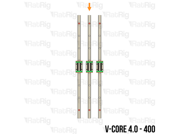
The SKUs for the V-Core 4.0 Z-axis linear rails vary depending on the size:
-
V-Core 4.0 - 300: 3x Linear Rail - HG15 400mm (SKU: HW3672GC)
-
Each rail has seven holes for mounting
-
V-Core 4.0 - 400: 3x Linear Rail - HG15 500mm (SKU: HW3416GC)
-
Each rail has eight holes for mounting
-
V-Core 4.0 - 500: 3x Linear Rail - HG15 600mm (SKU: HW3673GC)
-
Each rail has ten holes for mounting
-
-
-
M4x16 Cap Head Screw (SKU: HW3126SC)
-
T-Nut - Drop In Type for 30 Series - M4 (SKU: HW2774NC)
-
The required quantity of M4x16 Cap Head Screws and T-Nut - Drop In Type for 30 Series - M4 varies depending on size:
-
V-Core 4.0 - 300: 21 of each
-
V-Core 4.0 - 400: 24 of each
-
V-Core 4.0 - 500: 30 of each
-
2x align_3030_hg15 Printed Part (SKU: PP000005)
-
Please note: The alignment tools may have been printed in green or black. The design is the same regardless of colour
-
-
-
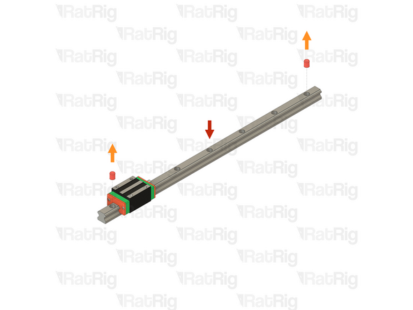
Prepared Z-axis linear rail from step 3
-
Remove both of the plastic stops in the linear rail
-
Make sure from this point onwards that the carriage does not leave the end of the linear rail
-
M4x16 Cap Head Screw
-
Insert an M4x16 Cap Head Screw into each mounting hole in the linear rail
-
T-Nut - Drop In Type for 30 Series - M4
-
Loosely thread a T-Nut onto each of the M4x16 Cap Head Screws. Do not tighten them at this point
-
Repeat the above instructions to assemble all three Z-axis linear rails
-
-
-
V-Core 4.0 Frame Assembly - Front-left corner
-
Prepared Z-axis linear rail assembly from the previous step
-
Align the Z-axis linear rail with the extrusion slot as shown
-
Make sure the small grease fitting is facing upwards
-
Make sure that all of the T-Nuts are slotted into the extrusion
-
Install the alignment tools, one near the top of the linear rail and the other near the bottom
-
Secure the linear rail to the frame assembly by tightening all of the M4x16 screws
-
Do not forget to tighten any M4x16 screws which are under the linear rail carriage
-
-
-
Remove both alignment tools
-
Move the carriage to the bottom of the linear rail
-
Repeat both the previous step, and this step to install the front-right Z-axis linear rail
-
Repeat both the previous step, and this step to install the rear Z-axis linear rail
-
-
-
3x NEMA17 Stepper Motor - 48mm (SKU: HW1078EC)
-
3x V-Core 4 Pillow Block - Nylon Injection Part (SKU: HW3848GC)
-
3x Coupler - Rigid Type - Black 25*20mm - 5mm to 8mm (SKU: HW2990GC)
-
3x Thrust Bearing F8-16M (SKU: HW2118WC)
-
12x M3x12 Cap Head Screw (SKU: HW1292SC)
-
-
-
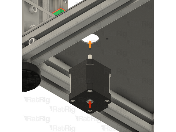
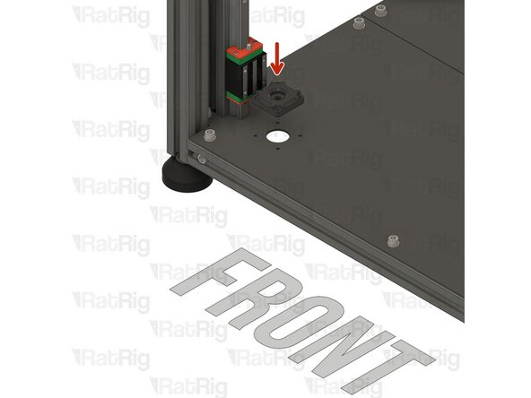
It is recommended to lay the machine assembly on its back to make installation of the Z-axis stepper motors easier
-
NEMA17 Stepper Motor - 48mm
-
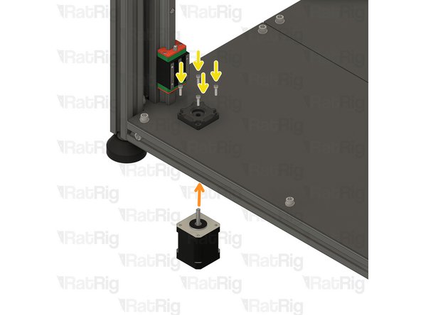
Install the stepper motor into the base plate as shown. The connector should face towards the back of the machine. Continue to support the stepper motor until it is secured later in this step
-
V-Core 4 Pillow Block - Nylon Injection Part
-
Place the V-Core 4 Pillow Block over the stepper motor shaft, aligning the four holes with the matching holes in the base plate
-
4x M3x12 Cap Head Screw
-
Insert each M3x12 Cap Head Screw through the Pillow Block, base plate, and thread them into the NEMA17 stepper motor. Once all 4 screws are threaded, fully tighten them to secure the assembly to the base plate
-
-
-
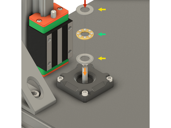
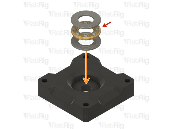
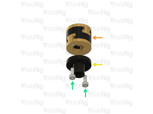
Thrust Bearing F8-16M - Please note: The thrust bearing has 3 components:
-
Install the thrust bearing into the Pillow Block as shown
-
2x End cap
-
Internal bearing race
-
It is recommended to add a drop or two of light oil (such as 3-in-1 or sewing machine oil) to the internal bearing race to lubricate it
-
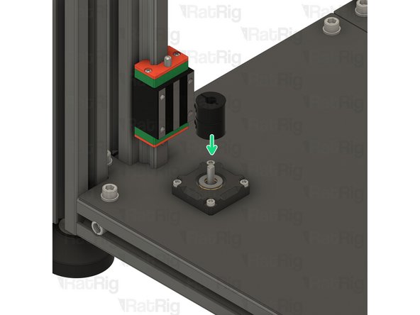
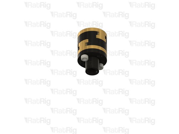
Coupler - Rigid Type - Black 25*20mm - 5mm to 8mm
-
Install the coupler onto the stepper motor shaft
-
Whilst gently pressing the coupler downwards to compress the thrust bearing, fully tighten the marked M3 Cap Head Screw to secure the coupler to the stepper motor shaft
-
-
-
Repeat step 10 and step 11 to install the front-right Z-axis stepper motor
-
The front-right stepper motor connector should face towards the back of the machine
-
Repeat step 10 and step 11 to install the rear Z-axis stepper motor
-
The rear stepper motor connector should face towards the front of the machine
-
Stand the machine assembly back on its feet at this point, there should be no further need to access the underside until the wiring section of the guide
-
-
-
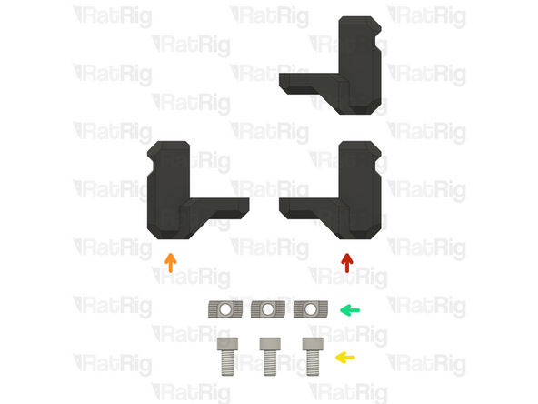
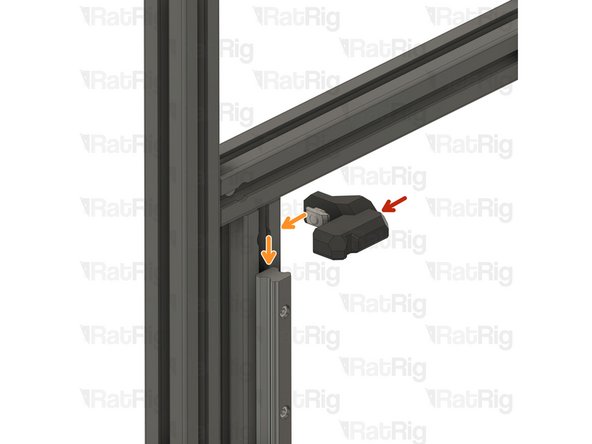
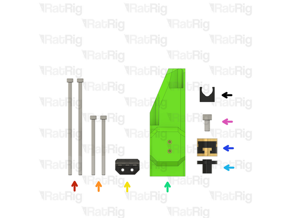
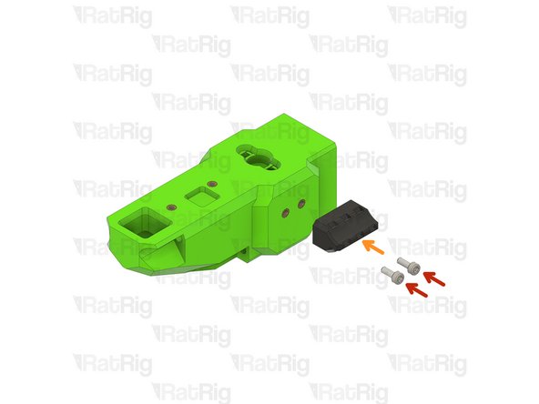
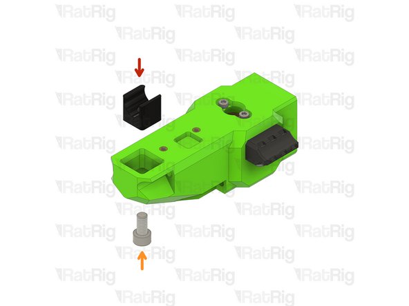
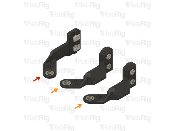
2x vc4_z_limit_right
-
1x vc4_z_limit_left
-
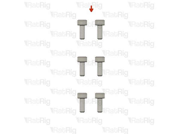
3x M6x12 Cap Head Screw
-
3x 3030 M6 Drop in T-Nut
-
Loosely thread the 3030 T-Nuts onto the M6x12 screws. Do not tighten them at this point.
-
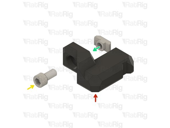
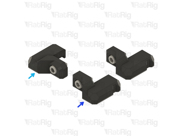
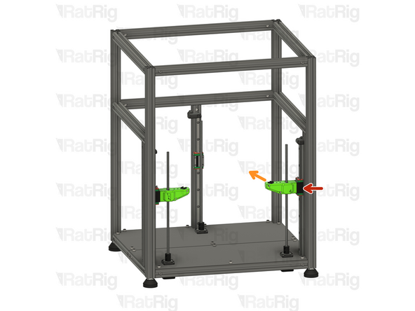
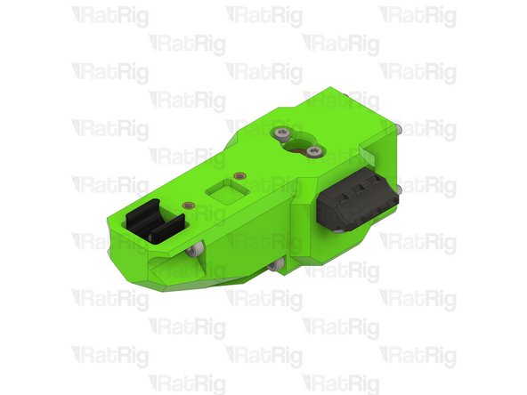
Prepare the all 3 Z-axis limit assemblies
-
1x left z limit assemblies
-
2x right z limit assembly
-
-
-
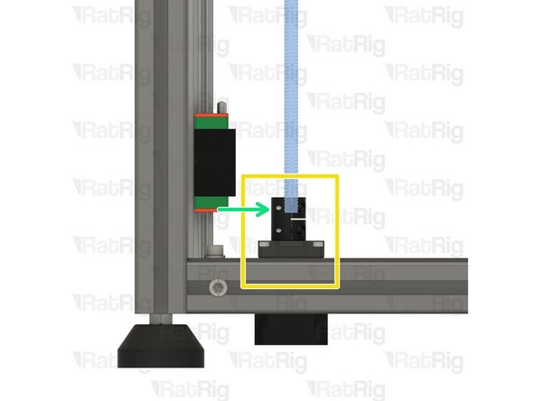
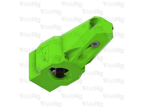
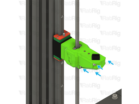
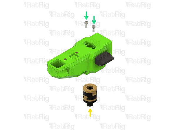
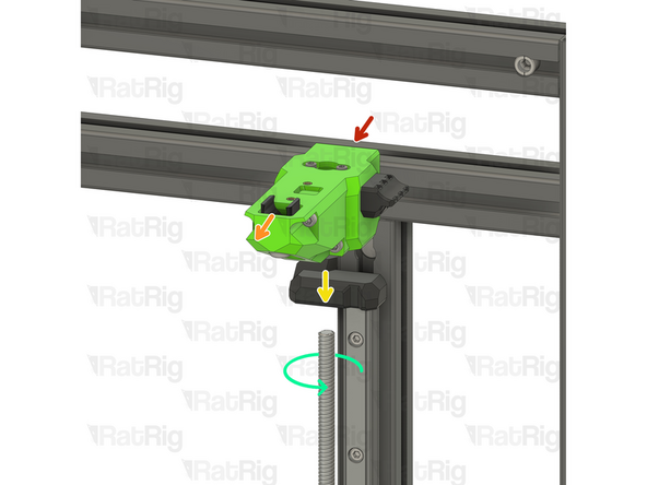
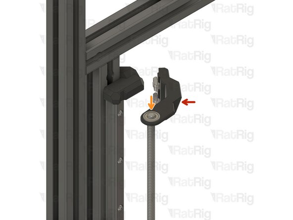
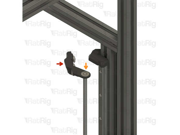
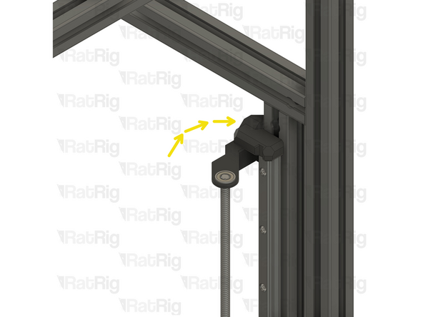
vc4_z_limit_left assembly
-
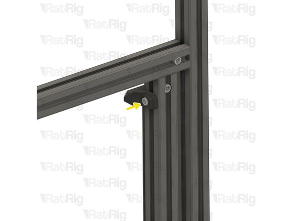
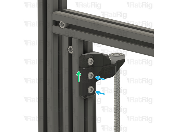
Insert the 3030 T-nut on the side of the extrusion and slide it down, until the vc4_z_limit_left assembly is flush with the linear rail
-
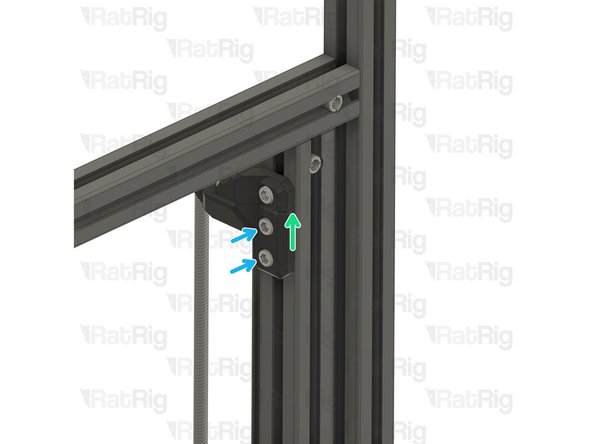
Tighten the M6x12 Cap Head Screw to secure the assembly
-
Take care not to over-tighten the M6x12 screws as you can damage the printed parts
-
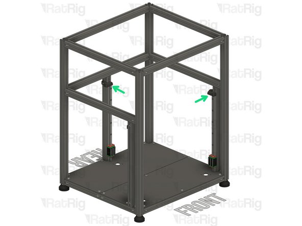
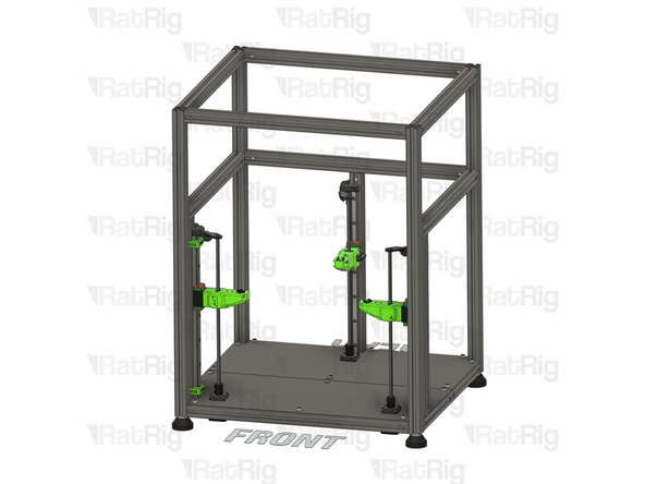
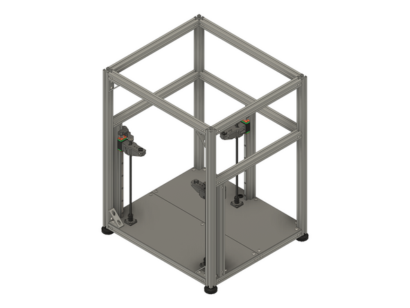
Repeat the previous steps and install the remaining vc4_z_limit_right assemblies
-
-
-
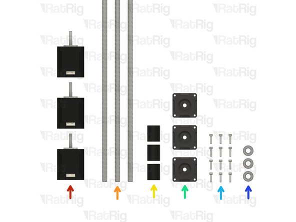
3x 48mm NEMA17 Stepper Motor
-
3x 375mm TR8x4 Lead Screws
-
3x Rigid Lead Screw Coupler
-
3x pillow_block printed part
-
More recent kits have this part injection molded, which is more accurate and easier to install.
-
12x M3x12 Cap Head Screw
-
3x Axial Thrust Bearing
-
-
-
pillow_block printed part
-
48mm NEMA17 Stepper Motor
-
Insert the NEMA17 motor into the base plate, as shown
-
M3x12 Cap Head Screw
-
Insert each M3x12 cap head screw through the pillow block, the base plate, and fasten them into the NEMA17 motor
-
-
-
Axial Thrust Bearing
-
The axial thrust bearing has three components. Two end caps and an inner bearing assembly.
-
Assemble the axial thrust bearing into the pillow_block as shown
-
Make sure that the thrust bearing is fully inserted into the printed part. The top ring of the thrust bearing should be flush with the top of the pillow_block.
-
If desired, you may add a drop of light oil to the inner bearing assembly of the thrust bearing
-
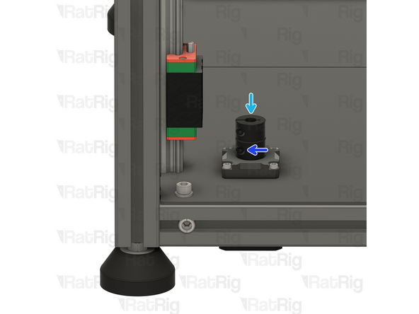
Install the lead screw coupler on to the exposed shaft of the NEMA17 motor. Use the smallest hole in the coupler for the stepper motor.
-
Apply downward pressure to the top of the lead screw coupler whilst tightening the marked screw
-
Tighten the marked M3 screw to secure the lead screw coupler to the motor shaft
-
-
-
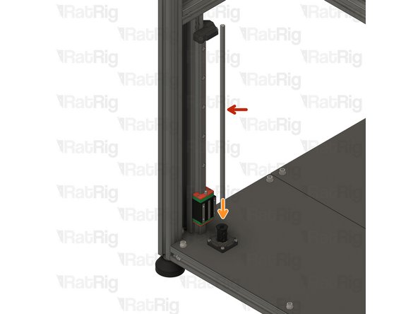
375mm TR8x4 Lead Screw
-
Install the lead screw in the Rigid Lead Screw Coupler
-
Ensure the Lead Screw doesn't touch the NEMA17 motor shaft.
-
Tighten the M3 screw on the coupler, locking the lead screw.
-
Repeat the previous steps and install the other 2 lead screws
-
-
-
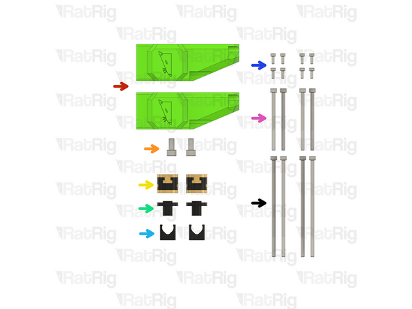
2x vc4_arm_front
-
2x M6x12 Cap Head Screw
-
2x Rat Rig Bi-Material Lead Screw Decoupler
-
2x TR8x4 POM Lead screw Nut
-
2x Rat Rig V-Core 4.0 - POM Arm Insert
-
8x M3x8 Cap Head Screw
-
4x M4x60 Cap Head Screw
-
4x M4x100 Cap Head Screw
-
-
-
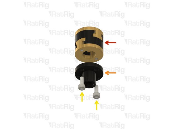
Rat Rig Bi-Material Lead Screw Decoupler
-
TR8x4 POM Lead screw Nut
-
M3x8 Cap Head Screw
-
Front bed arm assembly
-
Lead screw decoupler assembly
-
M3x8 Cap Head Screw
-
Install a lead screw decoupler assembly into each arm as shown
-
Take care not to over tighten the M3x8 screws as you damage the printed parts
-
-
-
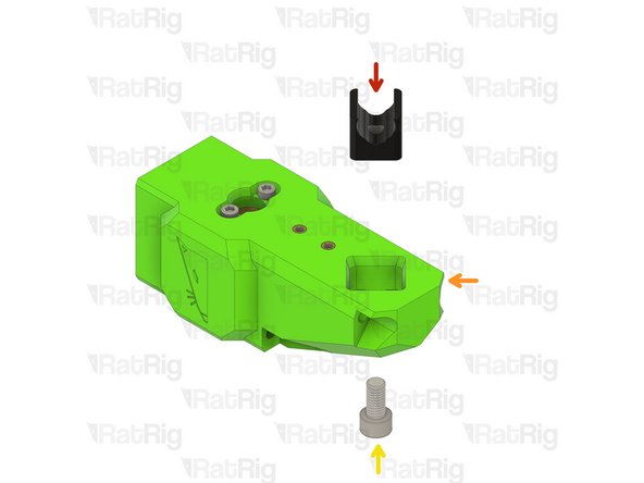
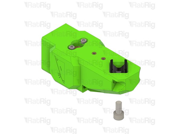
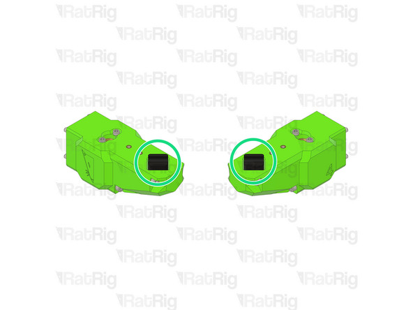
Rat Rig V-Core 4.0 - POM Arm Insert
-
Insert the POM arm insert, pay special attention to its orientation
-
Front arm assembly
-
M6x12 Cap Head Screw
-
Take care not to over tighten the M6x12 screws as you can damage the printed parts or the POM insert
-
-
-
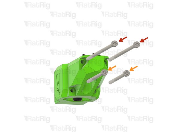
M4x100 Cap Head Screw
-
M4x60 Cap Head Screw
-
Insert the screws through the front arm
-
Repeat Steps 12, 13 and 14 to assemble another front arm, NOTE: the POM insert must be rotated
-
NOTE: the POM insert must be rotated 45º compared to the previous assembly
-
-
-
Front arm assembly
-
The POM insert groove must be aligned as shown
-
Thread the Lead Screw into the front arm assembly
-
Do not force the Lead Screw through the POM nut on the decoupler as this can cause damage. It should thread through smoothly
-
Tighten the M4 Cap Head Screws to secure the arm to the carriage
-
Take care not to overtighten the M4 screws as you may damage the printed parts
-
-
-
Repeat the previous Step and install the Right front arm
-
The POM insert groove must be aligned as shown
-
-
-
2x M4x100 Cap Head Screw
-
2x M4x60 Cap Head Screw
-
1x vc4_arm_cable printed part
-
1x vc4_arm_rear assembly
-
1x TR8x4 POM Lead screw Nut
-
1x Rat Rig Bi-Material Lead Screw Decoupler
-
1x M6x12 Cap Head Screw
-
1x Rat Rig V-Core 4.0 - POM Arm Insert
-
-
-
6x M3x8 Cap Head Screws
-
Rat Rig Bi-Material Lead Screw Decoupler
-
TR8x4 POM Lead screw Nut
-
M3x8 Cap Head Screw
-
-
-
2x M3x8 Cap Head Screws
-
vc4_arm_rear printed part
-
Insert the M3x8 Cap Head Screws into the vc4_arm_cable printed part and tighten them into the rear arm heat inserts.
-
Take care not to overtighten the M3x8 screws as you can damage the printed parts
-
Lead screw decoupler assembly
-
M3x8 Cap Head Screw
-
Install a lead screw decoupler assembly into the rear arm as shown
-
Take care not to overtighten the M3x8 screws as you can damage the printed parts
-
-
-
Rat Rig V-Core 4.0 - POM Arm Insert
-
Insert the POM arm insert, pay special attention to its orientation
-
M6x12 Cap Head Screw
-
Take care not to over tighten the M6x12 screws as you can damage the printed parts or the POM insert
-
M4x100 Cap Head Screw
-
M4x60 Cap Head Screw
-
Insert the screws through the front arm
-
-
-
Rear arm assembly
-
The POM insert groove must be aligned as shown
-
Install the rear arm through the rear bed arm and decoupler
-
Thread the Lead screw in to the rear arm assembly
-
Do not force the lead screw through the POM nut on the decoupler as this can cause damage. It should thread through smoothly
-
Tighten the M4 Cap Head Screws to secure the arm to the carriage
-
Take care not to over tighten the M4 screws as you damage the printed parts
-
-
-
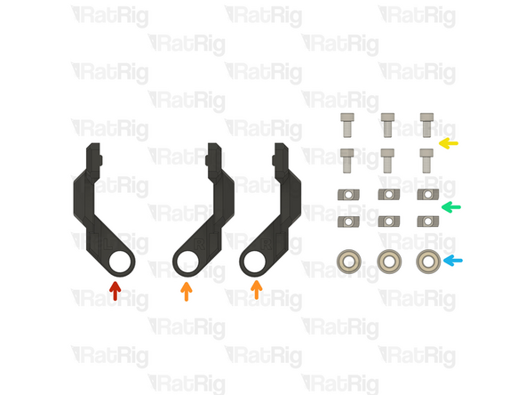
vc4_z_constraint_left
-
2x vc4_z_constraint_right
-
6x M6x12 Cap Head Screw
-
6x 3030 Drop-in T-Nut - M6
-
3x F688ZZ Ball Bearing
-
-
-
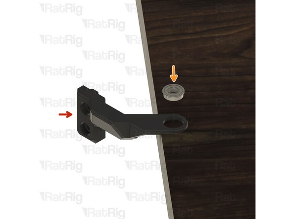
vc4_z_constraint
-
F688ZZ Ball Bearing
-
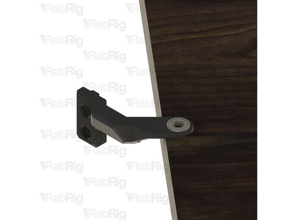
Insert the Bearing into the Z_constarin printed part
-
Make sure the bearing is inserted uniformly to avoid damaging the printed part - Use a flat surface like a wood table top to provide support to the printed part.
-
M6x12 Cap Head Screw
-
Insert an M6x12 cap head screw into each position on the lead screw constraint as shown
-
3030 Drop-in T-Nut - M6
-
Loosely thread a 3030 T-Nut onto each of the M6x12 screws. Do not tighten them at this point
-
-
-
Repeat the previous Step and assemble all the Z_constrains:
-
1x vc4_z_constraint_left assembly
-
2x vc4_z_constraint_right assembly
-
-
-
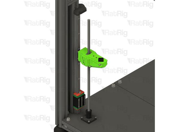
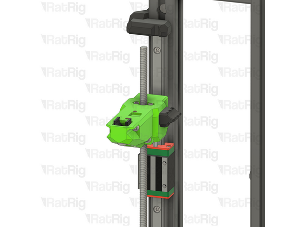
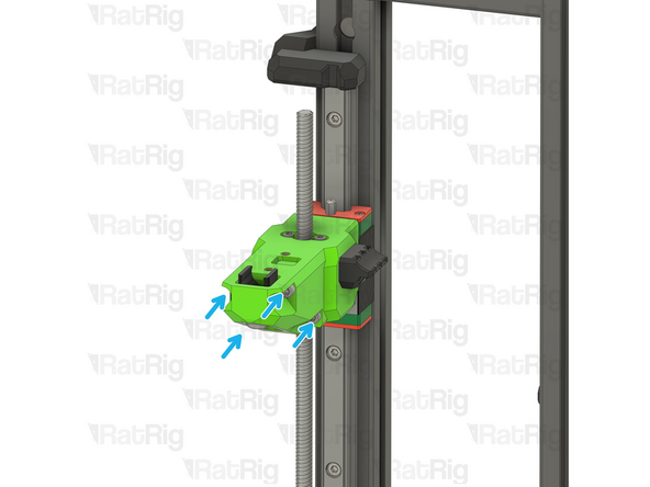
Left lead screw constraint assembly
-
Position the constraint assembly so that the left lead screw passes through the bearing
-
Rotate the constraint assembly anticlockwise and fit it to the rear 3030 extrusion as shown
-
Push the constraint assembly upwards until it touches the Z-axis limit printed part.
-
Fasten both M6x12 screws to secure the constraint assembly to the V-Core 4 frame
-
Take care not to over tighten the M6 screws as you damage the printed part
-
-
-
Right lead screw constraint assembly
-
Position the constraint assembly so that the right lead screw passes through the bearing
-
Rotate the constraint assembly clockwise and fit it to the rear 3030 extrusion as shown
-
Push the constraint assembly upwards until it touches the horizontal 3030 extrusion
-
Fasten both M6x12 screws to secure the constraint assembly to the V-Core 4 frame
-
Take care not to over tighten the M6 screws as you damage the printed part
-
Repeat the previous Steps and install the Rear Z constraint
-
-
-
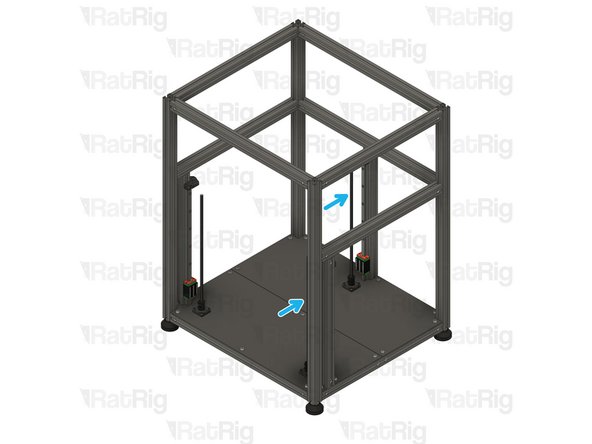
The assembly should look like this.
-
-
-
Continue with the next guide: 03. Y-Axis Linear Rails
-