-
-
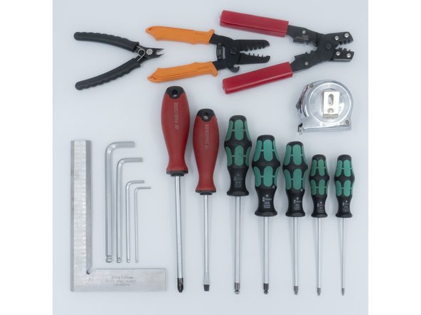
The following tools are required for this section of the guide:
-
Allen key / hex wrenches in the following sizes: 2.5mm & 5mm
-
Avoid using ball end hex wrenches where possible as they are more prone to damaging the heads of smaller screws
-
The following are recommended for this guide:
-
Paper towels
-
Disposable gloves
-
A light oil, such as 3-in-1 or sewing machine oil
-
-
-
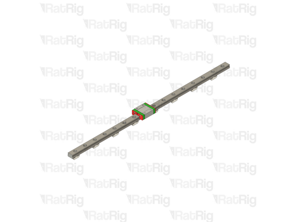
The linear rails are supplied with a protective oil coating on them. It is strongly recommended to prepare your work surface with paper towels and to wear disposable gloves
-
Paper Towels
-
Linear Rail
-
The oil on the rails protects them from rusting. You must either replace this oil after cleaning (as directed below), or make sure not to remove all of the original oil during preparation
-
An easy solution to both protect, and lubricate the rails, is using a light oil such as 3-in-1 or sewing machine oil
-
Apply a small amount of oil to a paper towel and then apply the oil to the rail by wiping it with the oiled paper towel. This may be done prior to, or after the installation of the linear rails
-
Do not remove the plastic stops installed in the ends of the linear rail at this point as they prevent the carriage from leaving the rail
-
More advanced users may wish to fully grease the rails & carriage with a specialised bearing lubricant. It is important to use the correct grade and make sure there are no additives such as PTFE, graphite, molybdenum disulfide, etc. The recommended grade of grease is EP00 or EP000 as these lubricate well, without being too viscous
-
-
-
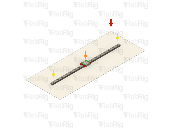
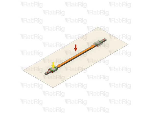
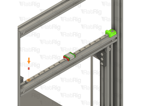
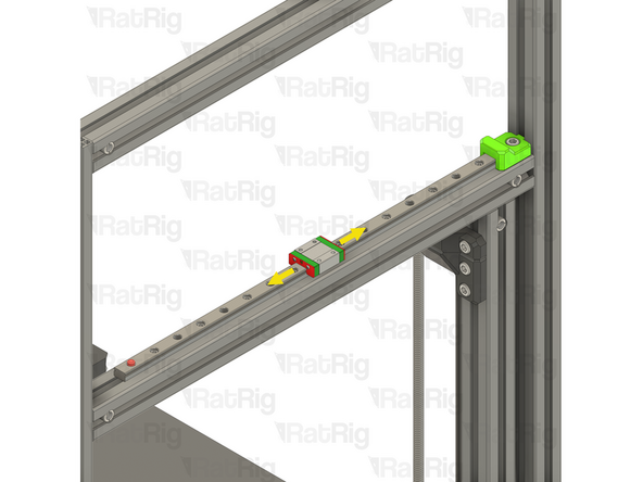
With the linear rail still on the absorbent paper towels, carefully and slowly move the carriage from one end of the rail to the other
-
The carriage should move smoothly over the entire length of the rail
-
Small changes in resistance are normal, but the carriage becoming much harder to push, or binding completely are not
-
Repeat the previous test whilst applying a small amount of force downwards on the carriage
-
The carriage will likely travel more smoothly when applying a downwards force, this is normal
-
If the carriage does not move smoothly, or binds completely, refer to the Linear Rail Troubleshooting Guide
-
-
-
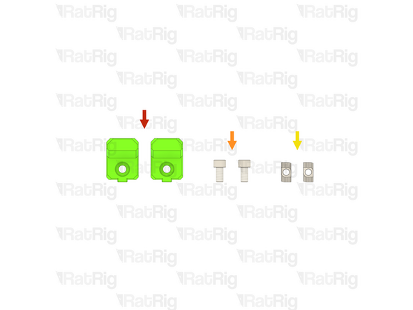
2x vc4_y_bumper Printed Part (SKU: PP000277)
-
2x M6x12 Cap Head Screw (SKU: HW1836SC)
-
2x T-Nut - Drop In Type for 30 Series - M6 (SKU: HW1361NC)
-
-
-
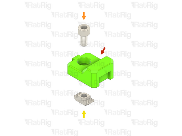
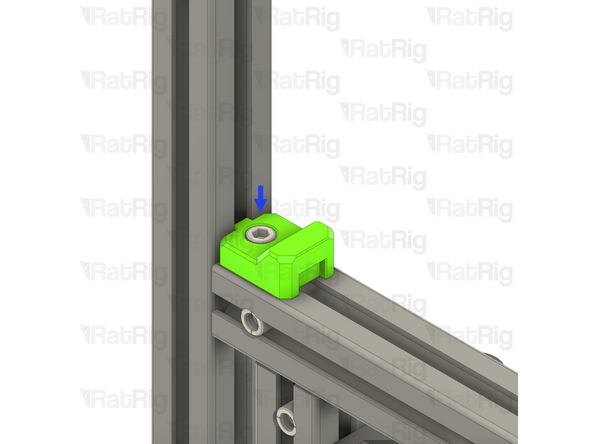
vc4_y_bumper Printed Part
-
M6x12 Cap Head Screw
-
T-Nut - Drop In Type for 30 Series - M6
-
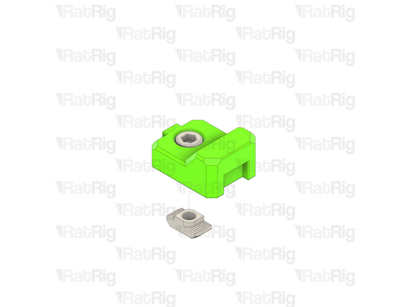
Insert an M6x12 Cap Head Screw into the hole in the printed part and then loosely thread a T-Nut onto it. Do not tighten it at this point
-
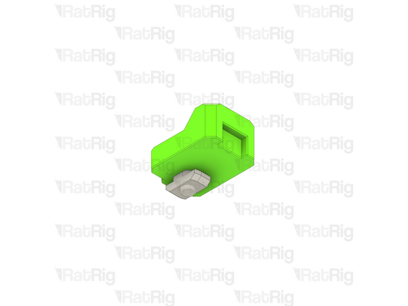
Repeat the above instructions to assemble two Y-axis bumpers
-
-
-
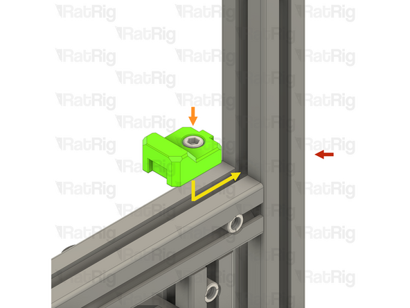
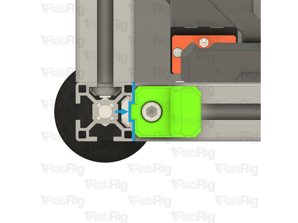
V-Core 4.0 Frame Assembly - Front-left corner
-
vc4_y_bumper assembly from step 5
-
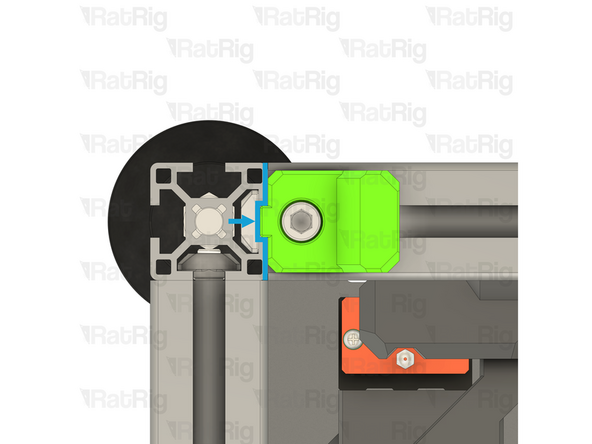
Align the Y-axis bumper with the extrusion slot as shown
-
Make sure that the T-Nut is slotted into the extrusion
-
Make sure the Y-axis bumper sits against the extrusion and the notch fits into the extrusion slot
-
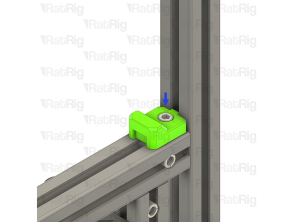
Fully tighten the M6x12 Cap Head Screw to secure the Y-axis bumper to the extrusion
-
Be careful not to overtighten the screw as you can damage the printed part
-
-
-
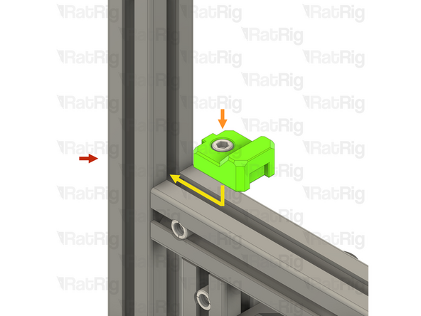
V-Core 4.0 Frame Assembly - Front-right corner
-
vc4_y_bumper assembly from step 5
-
Align the Y-axis bumper with the extrusion slot as shown
-
Make sure that the T-Nut is slotted into the extrusion
-
Make sure the Y-axis bumper sits against the extrusion and the notch fits into the extrusion slot
-
Fully tighten the M6x12 Cap Head Screw to secure the Y-axis bumper to the extrusion
-
Be careful not to overtighten the screw as you can damage the printed part
-
-
-
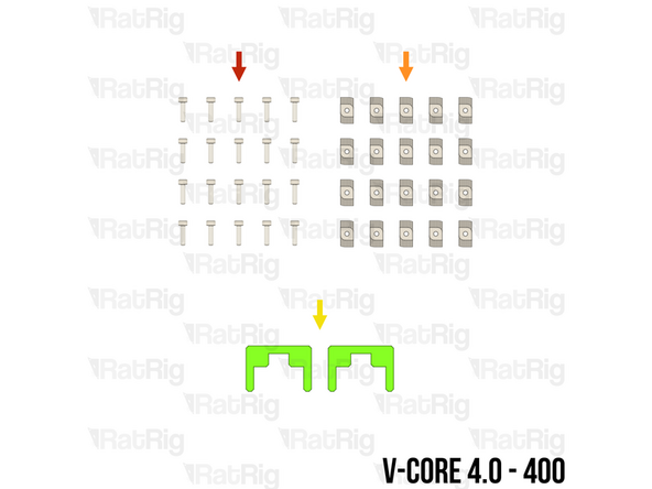
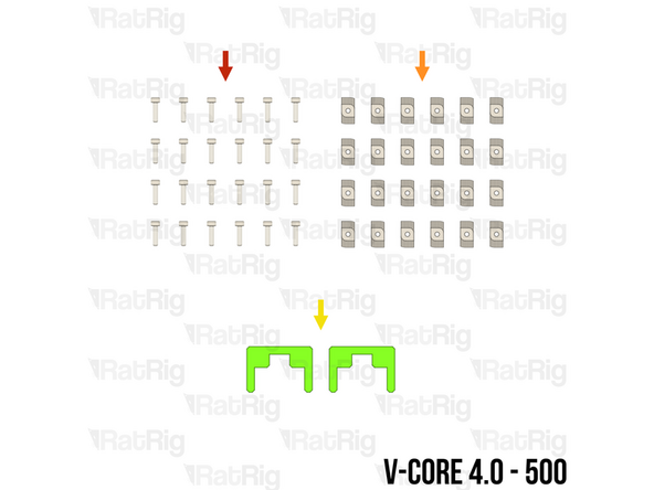
The SKUs for the V-Core 4.0 Y-axis linear rails vary depending on the size:
-
V-Core 4.0 - 300: 2x Linear Rail - MGN12 400mm (SKU: HW2036GC)
-
Each rail has fifteen holes for mounting
-
V-Core 4.0 - 400: 2x Linear Rail - MGN12 500mm (SKU: HW2034GC)
-
Each rail has nineteen holes for mounting
-
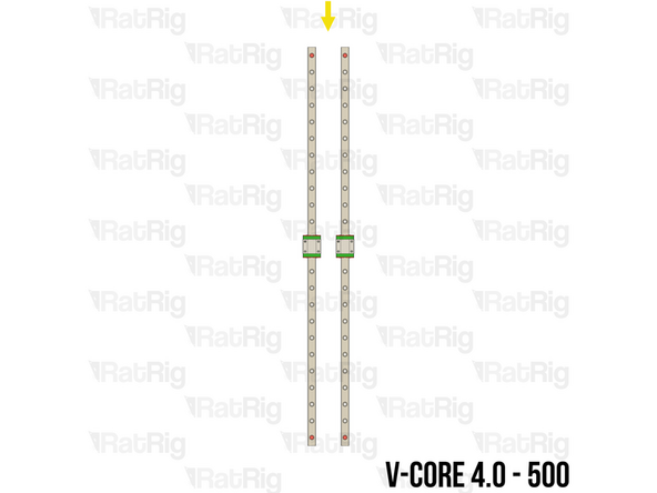
V-Core 4.0 - 500: 2x Linear Rail - MGN12 600mm (SKU: HW2356GC)
-
Each rail has twenty-three holes for mounting
-
-
-
M3x12 Cap Head Screw (SKU: HW1292SC)
-
T-Nut - Drop In Type for 30 Series - M3 (SKU: HW1821NC)
-
The required quantity of M3x12 Cap Head Screws and T-Nut - Drop In Type for 30 Series - M3 varies depending on size:
-
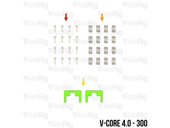
V-Core 4.0 - 300: 16 of each
-
V-Core 4.0 - 400: 20 of each
-
V-Core 4.0 - 500: 24 of each
-
2x align_3030_mgn12 Printed Part (SKU: PP000003)
-
Please note: The alignment tools may have been printed in green or black. The design is the same regardless of colour
-
-
-
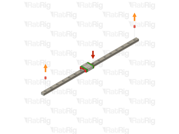
Prepared Y-axis linear rail from step 8
-
Remove both of the plastic stops in the linear rail
-
Make sure from this point onwards that the carriage does not leave the end of the linear rail
-
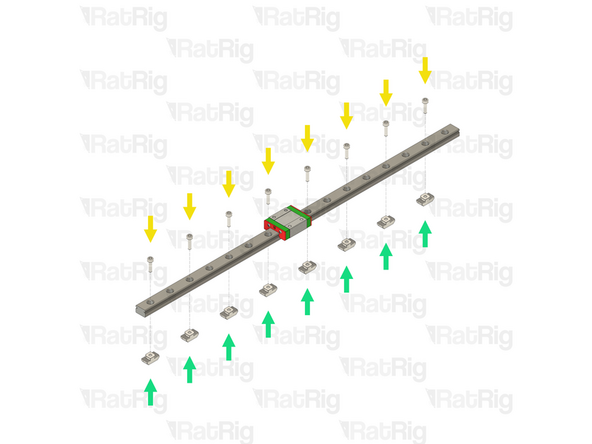
M3x12 Cap Head Screw
-
Starting at one end of the linear rail, insert an M3x12 Cap Head Screw into every other mounting hole
-
T-Nut - Drop In Type for 30 Series - M3
-
Loosely thread a T-Nut onto each of the M3x12 Cap Head Screws. Do not tighten them at this point
-
Repeat the above instructions to assemble both Y-axis linear rails
-
-
-
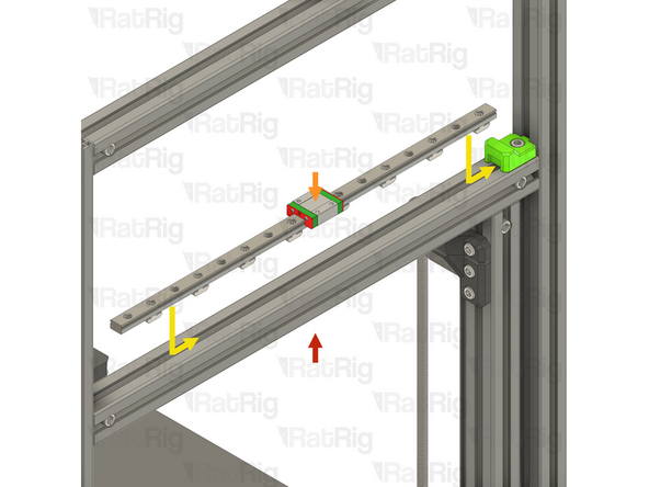
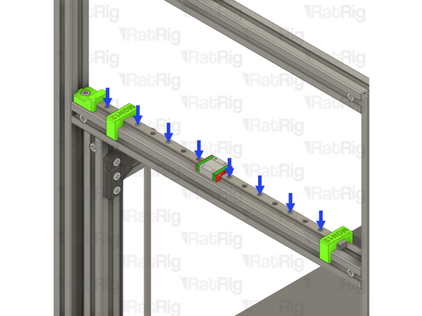
V-Core 4.0 Frame Assembly - Left-hand side
-
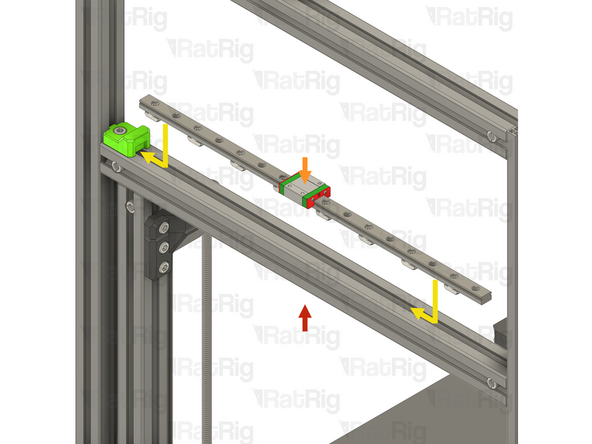
Prepared Y-axis linear rail assembly from the previous step
-
Align the Y-axis linear rail with the extrusion slot as shown
-
Make sure that all of the T-Nuts are slotted into the extrusion
-
Slide the linear rail towards the Y-axis bumper, making sure the tip of the linear rail fits into the cutout on the Y-axis bumper
-
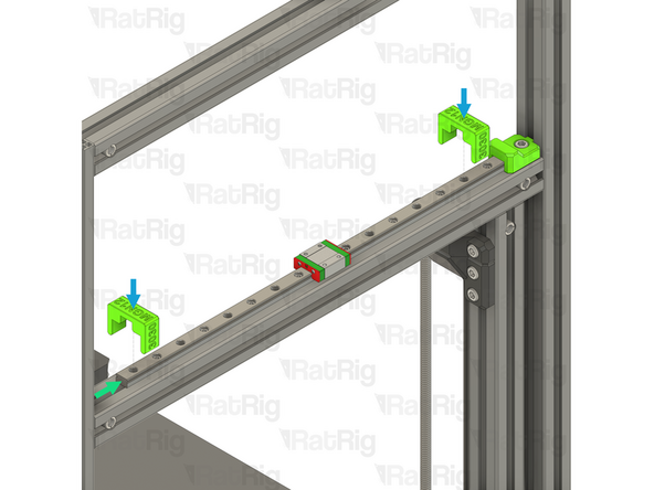
Install the alignment tools, one near the Y-axis bumper, and the other near the opposite end of the linear rail
-
Starting at one end, secure the linear rail to the frame assembly by tightening all of the M3x12 screws
-
Do not forget to tighten any M3x12 screws which are under the linear rail carriage
-
-
-
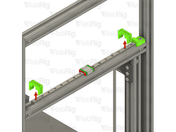
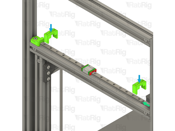
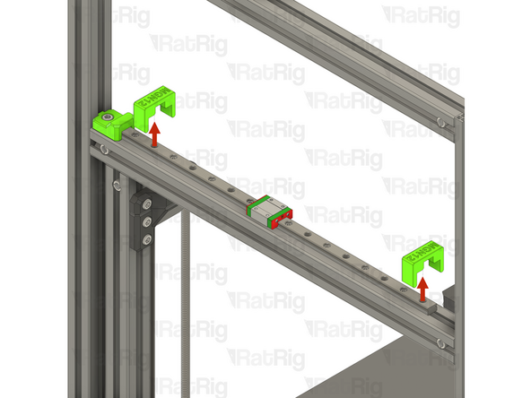
Remove both alignment tools
-
Set these aside until the next step
-
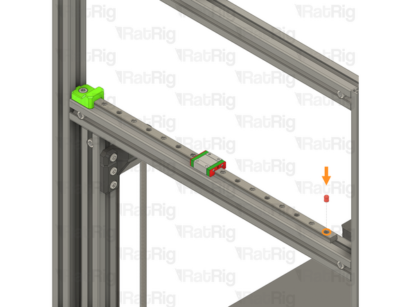
Optional: It is recommended, but not required, to reinstall one of the plastic stops in the linear rail to prevent the carriage from being able to leave the linear rail
-
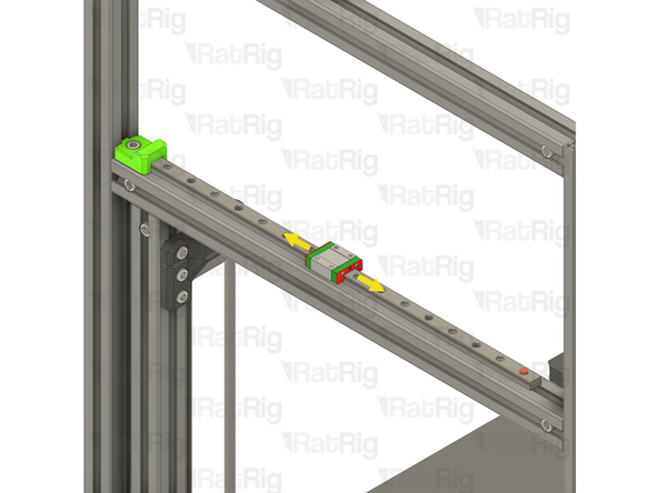
Carefully and slowly move the carriage from one end of the rail to the other to make sure it continues to move smoothly now that the linear rail is installed
-
Make sure the carriage does not leave the linear rail if the plastic stop is not installed
-
-
-
V-Core 4.0 Frame Assembly - Right-hand side
-
Prepared Y-axis linear rail assembly from step 10
-
Align the Y-axis linear rail with the extrusion slot as shown
-
Make sure that all of the T-Nuts are slotted into the extrusion
-
Slide the linear rail towards the Y-axis bumper, making sure the tip of the linear rail fits into the cutout on the Y-axis bumper
-
Install the alignment tools, one near the Y-axis bumper, and the other near the opposite end of the linear rail
-
Starting at one end, secure the linear rail to the frame assembly by tightening all of the M3x12 screws
-
Do not forget to tighten any M3x12 screws which are under the linear rail carriage
-
-
-
Remove both alignment tools
-
These alignment tools are no longer needed and can be stored away for future use
-
Optional: It is recommended, but not required, to reinstall one of the plastic stops in the linear rail to prevent the carriage from being able to leave the linear rail
-
Carefully and slowly move the carriage from one end of the rail to the other to make sure it continues to move smoothly now that the linear rail is installed
-
Make sure the carriage does not leave the linear rail if the plastic stop is not installed
-
-
-
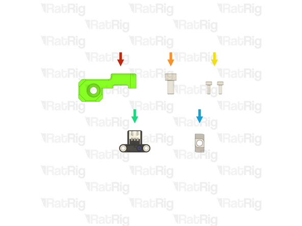
1x Prepared Y-axis endstop mount printed part from step 13 of the Preparations guide
-
1x M6x12 Cap Head Screw (SKU: HW1836SC)
-
2x M3x8 Cap Head Screw (SKU: HW1502SC)
-
1x Rat Rig Endstop v1.1 - Omron - NC (SKU: HW3787MK)
-
1x T-Nut - Drop In Type for 30 Series - M6 (SKU: HW1361NC)
-
-
-
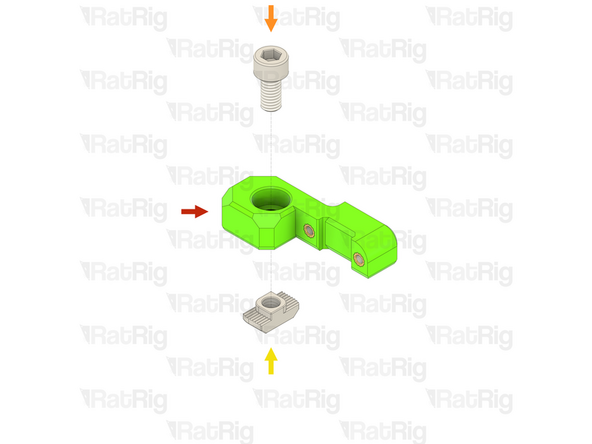
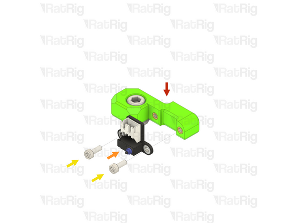
Prepared Y-axis endstop mount printed part
-
M6x12 Cap Head Screw
-
T-Nut - Drop In Type for 30 Series - M6
-
Insert an M6x12 Cap Head Screw into the marked hole in the printed part and then loosely thread a T-Nut onto it. Do not tighten the T-Nut at this point
-
-
-
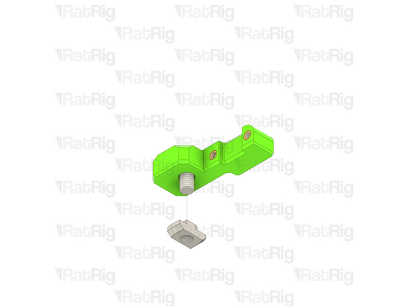
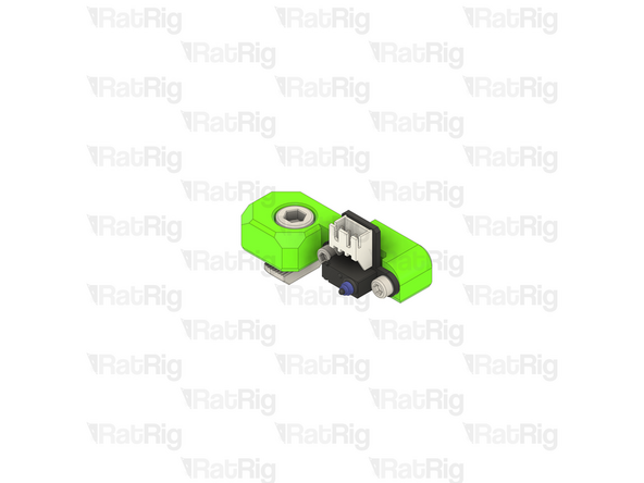
Y-axis endstop assembly from the previous step
-
Rat Rig Endstop v1.1 - Omron - NC
-
Align the Rat Rig Endstop with the Y-axis endstop assembly as shown. Make sure that the connector on the endstop faces upwards as shown
-
2x M3x8 Cap Head Screw
-
Tighten both M3x8 Cap Head Screws to secure the endstop to the printed part
-
Be careful not to overtighten the screws as you can damage the endstop or the printed part
-
-
-
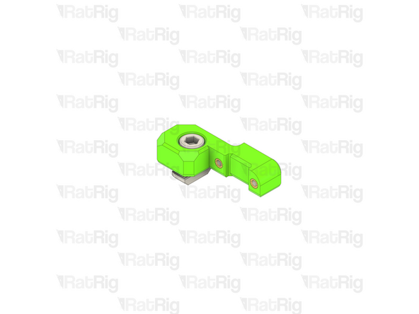
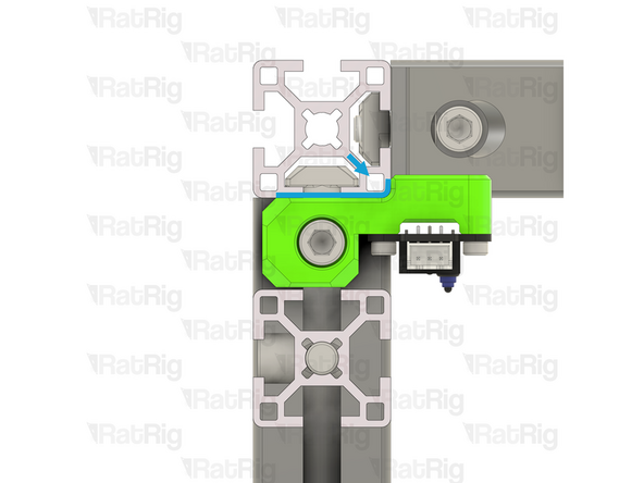
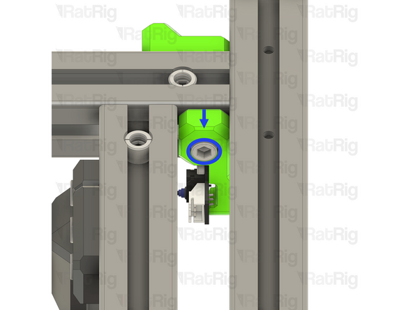
V-Core 4.0 Frame Assembly - Front-left corner
-
Y-axis endstop assembly from the previous step
-
Align the Y-axis endstop assembly with the extrusion slot as shown
-
Make sure that the T-Nut is slotted into the extrusion
-
Make sure the Y-axis endstop assembly sits against the extrusion and the curve in the printed part fits around the extrusion corner
-
Fully tighten the M6x12 Cap Head Screw to secure the Y-axis endstop assembly to the extrusion
-
Be careful not to overtighten the screw as you can damage the printed part
-
-
-
The next guide to follow depends on the variant of V-Core 4.0 you are building:
-
If you are building a CoreXY variant of the V-Core 4.0, then please continue to 04. Motion System - CoreXY
-
If you are building a Hybrid or IDEX variant of the V-Core 4.0, then please continue to 05. Motion System - Hybrid or IDEX
-


Cancel: I did not complete this guide.
43 other people completed this guide.