
Video Overview
-
-
1x 40mm NEMA17 Stepper Motor
-
y_motor_cage printed part
-
4x M6x12 Cap Head Screw
-
4x M3x8 Cap Head Screw
-
1x 20 Tooth 2GT Timing Pulley for 9mm Belt
-
4x 3030 Square T-Nut - M6
-
1x M8x30 Cap Head Screw
-
-
-
y_motor_cage printed part
-
M6x12 Cap Head Screw
-
3030 Square T-Nut - M6
-
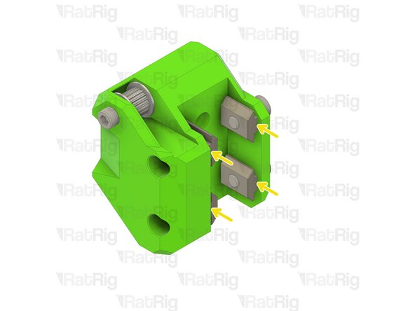
Loosely thread the 3030 T-Nuts onto the M6x12 screws. Do not tighten them at this point.
-
40mm NEMA17 Stepper Motor
-
Install the NEMA17 with its connector pointing downwards
-
Fasten the M3x8 screws to secure the stepper motor to the mount
-
Take care not to over tighten the M3x8 screws as you can damage the printed part
-
-
-
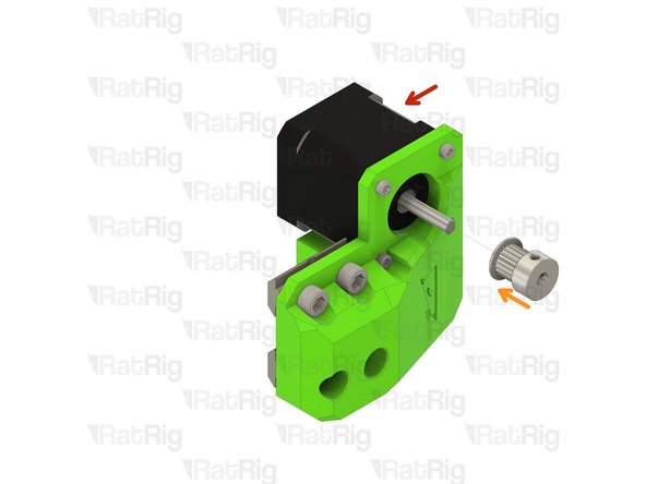
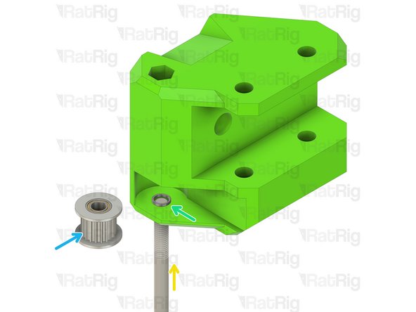
Assembly from Step 2
-
20 Tooth 2GT Timing Pulley for 9mm Belt
-
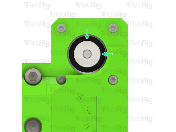
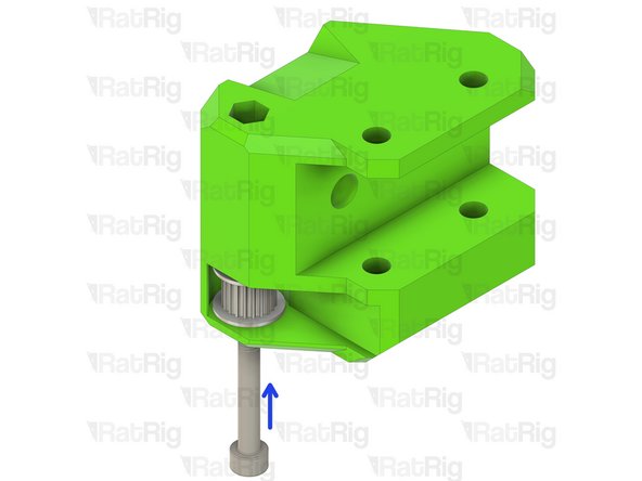
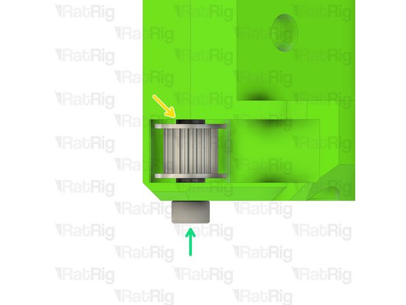
Position the timing pulley as shown. The end of the stepper shaft should be flush with the end of the pulley
-
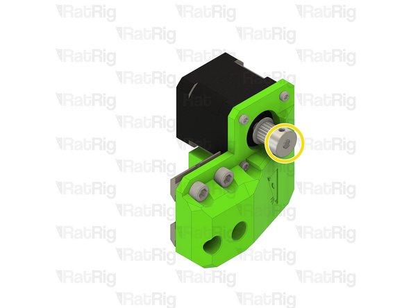
Fasten the two grub screws on the timing pulley to secure it to the stepper motor shaft
-
-
-
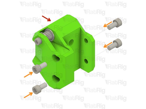
Assembly from Step 3
-
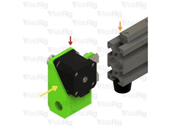
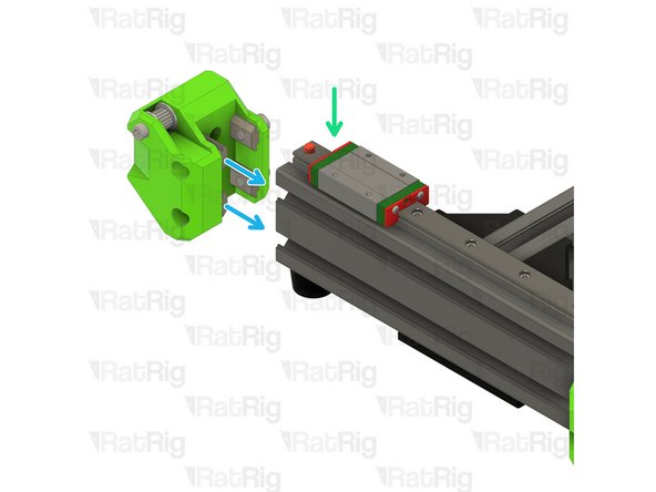
V-Minion Frame Assembly
-
Install the Y-axis motor assembly onto the V-Minion frame as shown. The 3030 T-nuts will slide into the 3060 extrusion
-
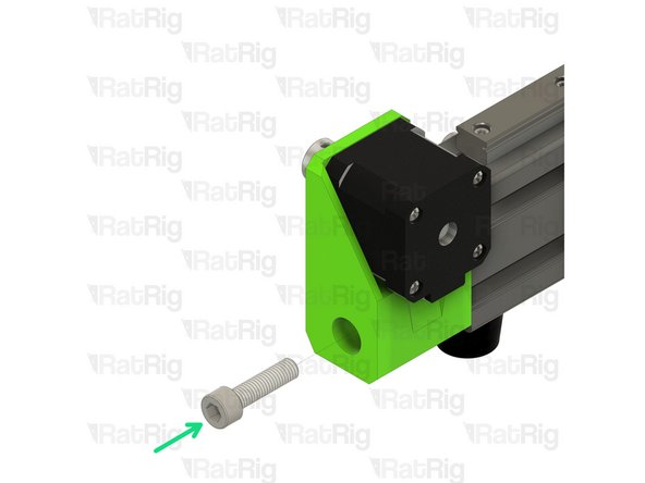
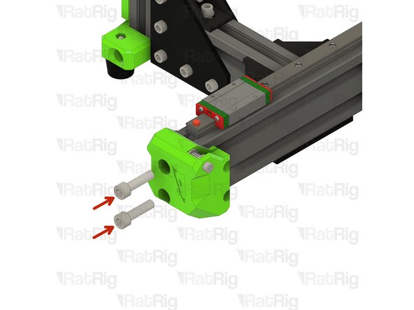
M8x30 Cap Head Screw
-
Fasten the M8x30 screw through the printed part and into the end of the 3060 extrusion
-
Take care not to over tighten the M8x30 screws as you can damage the printed part or the threads in the 3060 extrusion
-
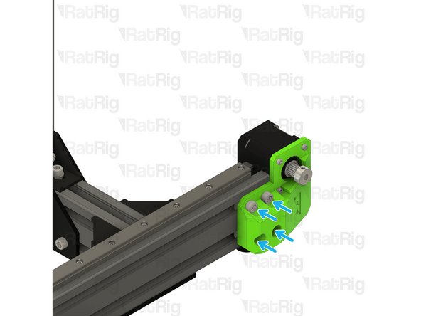
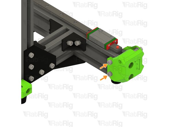
Fasten all four M6x12 screws to secure the mount to the frame
-
Take care not to over tighten the M6x12 screws as you can damage the printed part
-
-
-
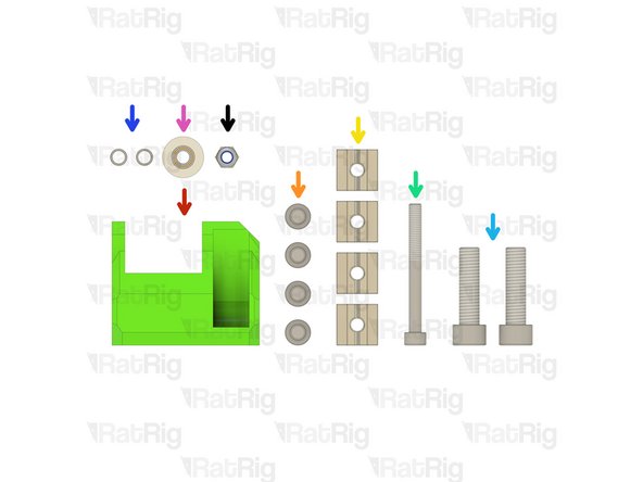
y_idler printed part
-
4x M6x12 Cap Head Screw
-
4x 3030 Square T-Nut - M6
-
1x M5x50 Cap Head Screw
-
2x M8x30 Cap Head Screw
-
2x Micro Precision Shim
-
1x 20 Tooth 2GT Idler Pulley for 9mm Belt
-
1x M5 Nylon Locking Hex Nut
-
-
-
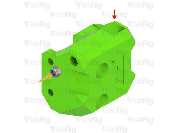
y_idler printed part
-
M5 Nylon Locking Hex Nut
-
Insert the M5 nylon locking nut into the printed part as shown
-
M5x50 Cap Head Screw
-
Install one precision micro shim onto the M5x50 screw
-
Install the toothed 2GT idler onto the M5x50 screw
-
Insert the M5x50 cap head screw further in preparation for the next step
-
-
-
Micro Precision Shim
-
Install the second precision micro shim onto the M5x50 screw
-
The assembly should look as shown, a micro precision shim on either side of the toothed idler
-
Fasten the M5x50 screw through the y_idler, into the M5 nylon lock nut
-
Check that the toothed idler rotates without binding. If the idler is difficult to rotate, loosen the M5x50 screw until the idler rotates smoothly
-
-
-
Assembly from Step 7
-
M6x12 Cap Head Screw
-
3030 Square T-Nut - M6
-
Loosely thread the 3030 T-Nuts onto the M6x12 screws. Do not tighten them at this point
-
V-Minion Frame Assembly
-
Install the Y-axis idler assembly onto the V-Minion frame as shown. The 3030 T-nuts will slide into the 3060 extrusion
-
If you have any problems aligning all of the square t-nuts at the same time, you can alternately pre-install some, or all of them, into the extrusion and add the screws afterwards
-
-
-
M8x30 Cap Head Screw
-
Fasten the M8x30 screw through the printed part and into the end of the 3060 extrusion
-
Take care not to over tighten the M8x30 screws as you can damage the printed part or the threads in the 3060 extrusion
-
Fasten all four M6x12 screws to secure the mount to the frame
-
Take care not to over tighten the M6x12 screws as you can damage the printed part
-


Cancel: I did not complete this guide.
18 other people completed this guide.