Video Overview
-
-
1x 40mm NEMA17 Stepper Motor
-
y_motor_cage printed part
-
4x M6x12 Cap Head Screw
-
4x M3x8 Cap Head Screw
-
1x 20 Tooth 2GT Timing Pulley for 9mm Belt
-
4x 3030 Square T-Nut - M6
-
1x M8x30 Cap Head Screw
-
-
-
y_motor_cage printed part
-
M6x12 Cap Head Screw
-
3030 Square T-Nut - M6
-
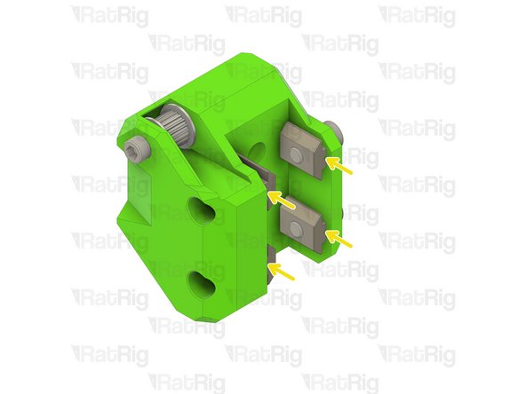
Loosely thread the 3030 T-Nuts onto the M6x12 screws. Do not tighten them at this point.
-
40mm NEMA17 Stepper Motor
-
Install the NEMA17 with its connector pointing downwards
-
Fasten the M3x8 screws to secure the stepper motor to the mount
-
Take care not to over tighten the M3x8 screws as you can damage the printed part
-
-
-
Assembly from Step 2
-
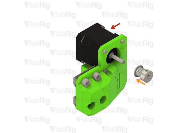
20 Tooth 2GT Timing Pulley for 9mm Belt
-
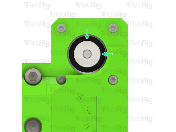
Position the timing pulley as shown. The end of the stepper shaft should be flush with the end of the pulley
-
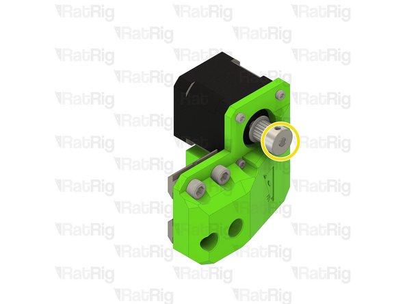
Fasten the two grub screws on the timing pulley to secure it to the stepper motor shaft
-
-
-
Assembly from Step 3
-
V-Minion Frame Assembly
-
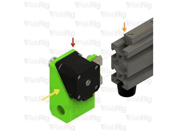
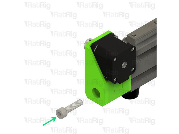
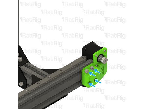
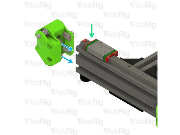
Install the Y-axis motor assembly onto the V-Minion frame as shown. The 3030 T-nuts will slide into the 3060 extrusion
-
M8x30 Cap Head Screw
-
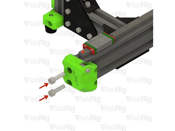
Fasten the M8x30 screw through the printed part and into the end of the 3060 extrusion
-
Take care not to over tighten the M8x30 screws as you can damage the printed part or the threads in the 3060 extrusion
-
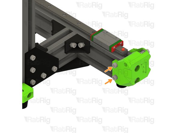
Fasten all four M6x12 screws to secure the mount to the frame
-
Take care not to over tighten the M6x12 screws as you can damage the printed part
-
-
-
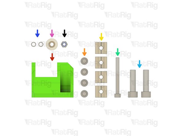
y_idler printed part
-
4x M6x12 Cap Head Screw
-
4x 3030 Square T-Nut - M6
-
1x M5x50 Cap Head Screw
-
2x M8x30 Cap Head Screw
-
2x Micro Precision Shim
-
1x 20 Tooth 2GT Idler Pulley for 9mm Belt
-
1x M5 Nylon Locking Hex Nut
-
-
-
y_idler printed part
-
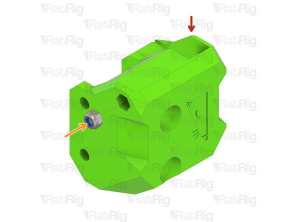
M5 Nylon Locking Hex Nut
-
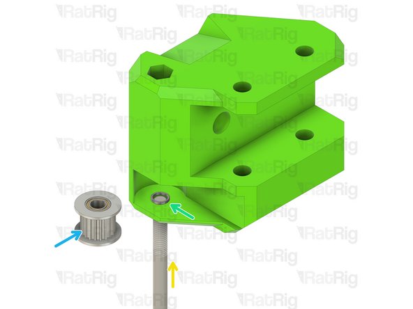
Insert the M5 nylon locking nut into the printed part as shown
-
M5x50 Cap Head Screw
-
Install one precision micro shim onto the M5x50 screw
-
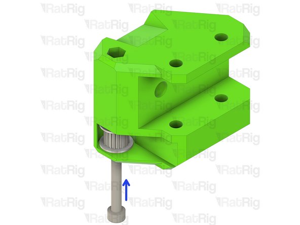
Install the toothed 2GT idler onto the M5x50 screw
-
Insert the M5x50 cap head screw further in preparation for the next step
-
-
-
Micro Precision Shim
-
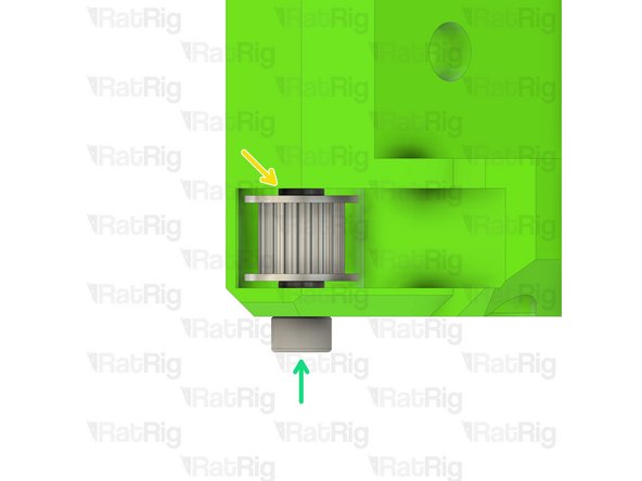
Install the second precision micro shim onto the M5x50 screw
-
The assembly should look as shown, a micro precision shim on either side of the toothed idler
-
Fasten the M5x50 screw through the y_idler, into the M5 nylon lock nut
-
Check that the toothed idler rotates without binding. If the idler is difficult to rotate, loosen the M5x50 screw until the idler rotates smoothly
-
-
-
Assembly from Step 7
-
M6x12 Cap Head Screw
-
3030 Square T-Nut - M6
-
Loosely thread the 3030 T-Nuts onto the M6x12 screws. Do not tighten them at this point
-
V-Minion Frame Assembly
-
Install the Y-axis idler assembly onto the V-Minion frame as shown. The 3030 T-nuts will slide into the 3060 extrusion
-
If you have any problems aligning all of the square t-nuts at the same time, you can alternately pre-install some, or all of them, into the extrusion and add the screws afterwards
-
-
-
M8x30 Cap Head Screw
-
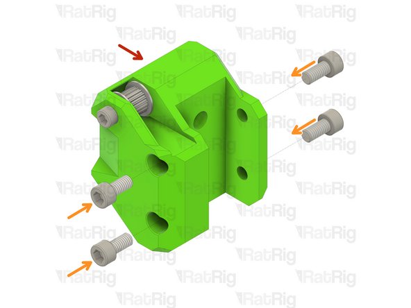
Fasten the M8x30 screw through the printed part and into the end of the 3060 extrusion
-
Take care not to over tighten the M8x30 screws as you can damage the printed part or the threads in the 3060 extrusion
-
Fasten all four M6x12 screws to secure the mount to the frame
-
Take care not to over tighten the M6x12 screws as you can damage the printed part
-
In step 8, observe the orientation of the 3030 square nuts. There is not enough room to rotate these 90 degrees, so pay attention. When placing the second shim in place, sticking it to a piece of tape will let you wiggle it into place. Once caught on the tip of the machine screw, just pull the tape out before snugging up. Makes like much easier than fooling with tweezers or skinny screwdrivers.
In step 8, observe the orientation of the 3030 square nuts. There is not enough room to rotate these 90 degrees, so pay attention. When placing the second shim in place, sticking it to a piece of tape will let you wiggle it into place. Once caught on the tip of the machine screw, just pull the tape out before snugging up. Makes like much easier than fooling with tweezers or skinny screwdrivers.
Cancel: I did not complete this guide.
18 other people completed this guide.


