Steps
19
- 04. Advanced Bundle 19 steps

In Progress
This guide is currently being written. Reload periodically to see the latest changes.

Private
This guide will not appear in search results and can only be viewed by team members!
Quiz
0
Introduction
BEFORE STARTING:
Before beginning this guide, you must prepare all the necessary wires for the assembly. Below is a list of the required wires. The following nomenclature will be used: (Wire Length)_(AWG)_(Wire Color)_(A-End Connector)_(B-End Connector)_(ID number).
Use a small piece of tape to label each wire to ensure a smooth assembly process.
- 700mm - 16AWG RED (A-Ferrule, B-Ferrule) (4)
- 700mm - 16AWG BLACK (A-Ferrule, B-Fork) (5)
- 120mm - 16AWG RED (A-Fork, B-Fork) (6)
- 600mm - 16AWG RED (A-Fork, B-Ferrule) (7)
- 600mm - 16AWG BLACK (A-Fork, B-Ferrule) (8)
- 150mm - 22AWG BLACK (A-Fork, B-Ferrule) (9)
- 150mm - 22AWG RED (A-Ferrule, B-Ferrule) (10)
- 150mm - 22AWG BLACK (A-Ferrule, B-Ferrule) (11)
- 400mm - 22AWG RED (A-Ferrule, B-Fork) (12)
- 2x 400mm - 22AWG BLACK (A-Ferrule, B-Fork) (13)
- 4x 550mm - Multicore 3 Conductor - 24AWG BLACK (A-(3x)Ferrule, B-(3x)Ferrule) (14)
- 4x 800mm - 16AWG RED (A-Fork, B-Ferrule) (15)
- 4x 800mm - 16AWG BLACK (A-Fork, B-Ferrule) (16)
- 4x 30mm - 22AWG BLACK (A-Ferrule, B-Ferrule) (17)
- 100mm - 22AWG RED (A-Ferrule, B-Ferrule) (18)
- 900mm - Multicore 2 Conductor - 24AWG (A-2xFerrule, B-2xFerrule) (19)
-
-
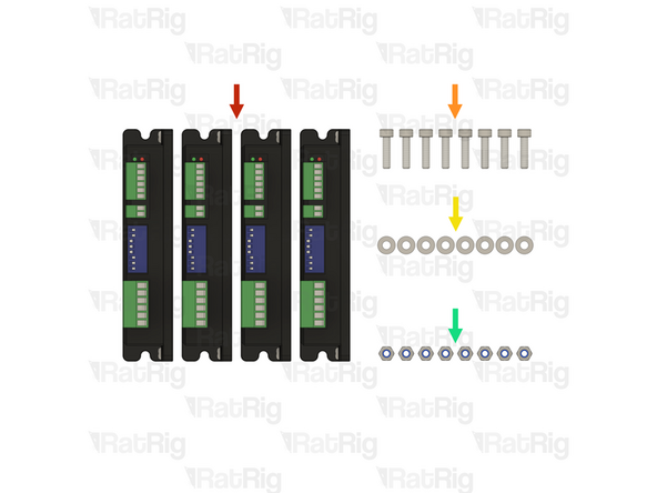
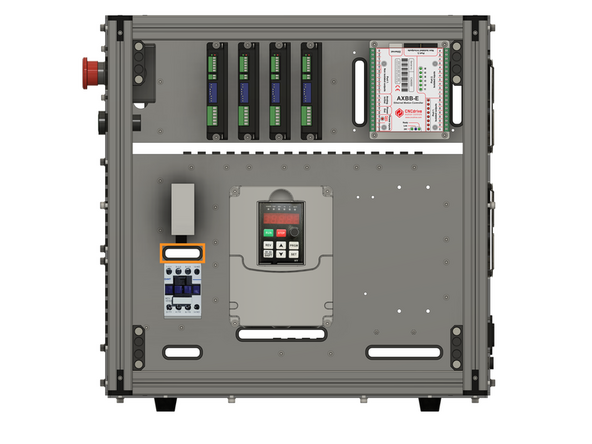
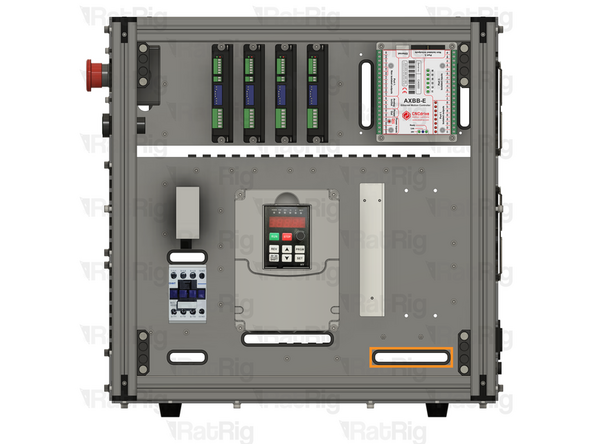
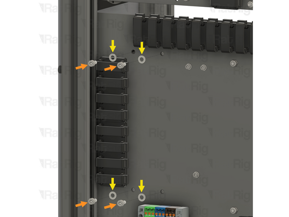
4x Stepper driver - OMC DM542T
-
8x M4x16 cap head screw
-
8x M4 washer
-
8x M4 locking hex nut
-
-
-
1x Stepper driver - OMC DM542T
-
2x M4x16 cap head screw
-
2x M4 washer
-
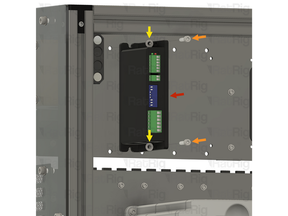
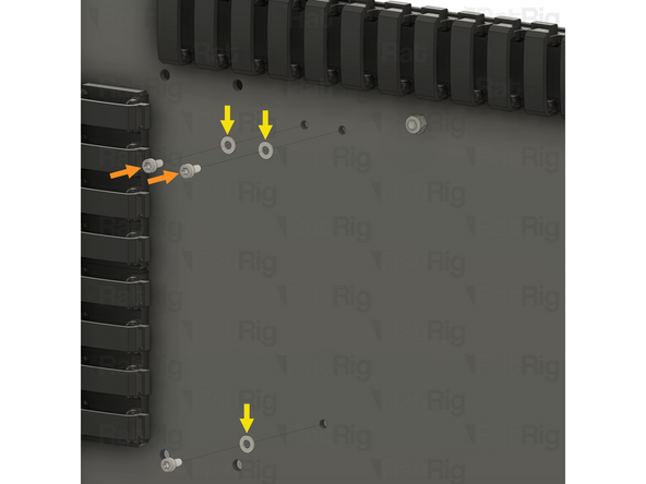
Install an M4 washer on to each M4x16 screw
-
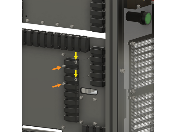
Align the stepper driver with the holes on the panel, and insert an M4x16 screw through the stepper driver and panel as shown
-
Keep supporting the stepper driver until the locking hex nuts are installed in the next step
-
-
-
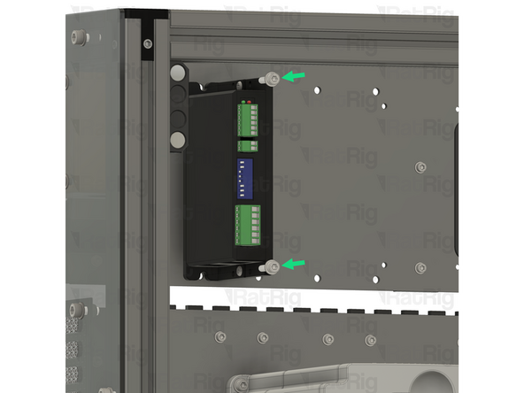
2x M4 locking hex nut
-
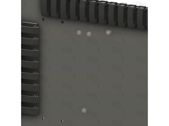
Install an M4 locking hex nut on to each of the M4x16 screws and tighten them to secure the stepper driver to the panel
-
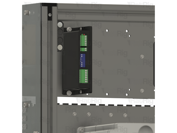
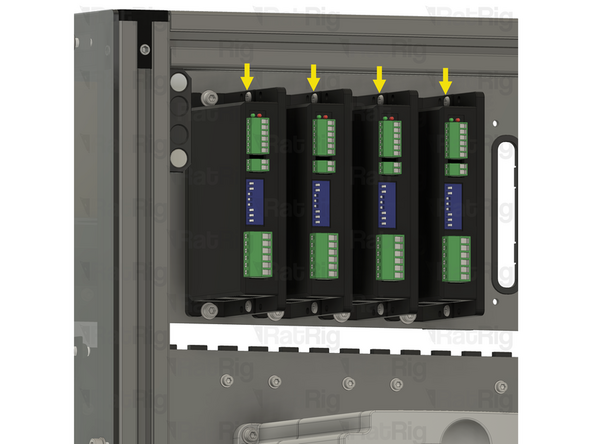
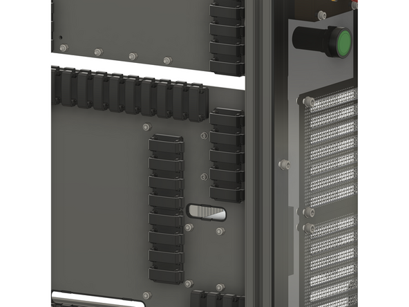
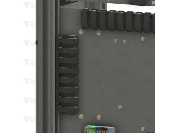
Repeat the previous step, and this step, to install the remaining 3 stepper drivers as shown
-
-
-
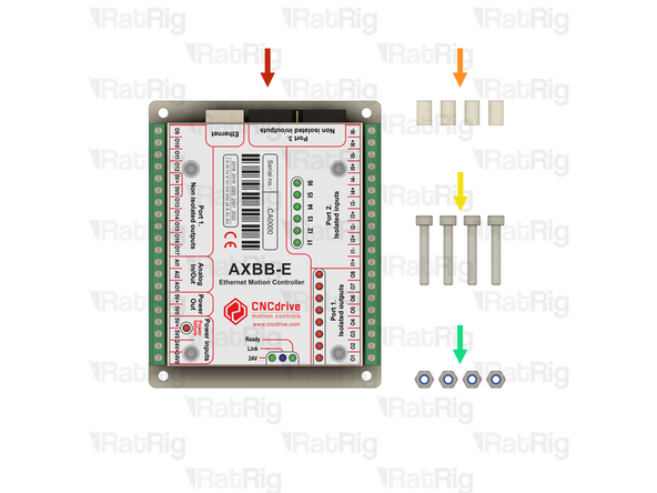
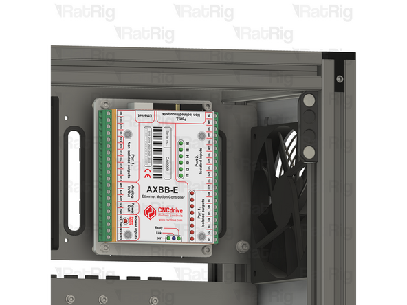
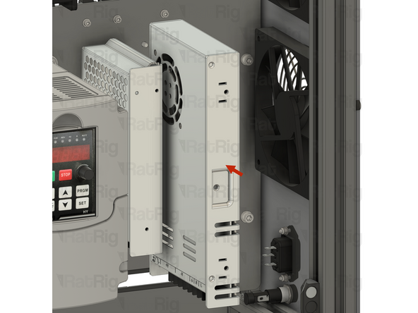
1x CNCDrive AXBB-E CNC controller
-
4x Spacer - Nylon - 4.2x6.3x10mm
-
4x M4x25 cap head screw
-
4x M4 locking hex nut
-
-
-
1x CNCDrive AXBB-E CNC controller
-
4x Spacer - Nylon - 4.2x6.3x10mm
-
4x M4x25 cap head screw
-
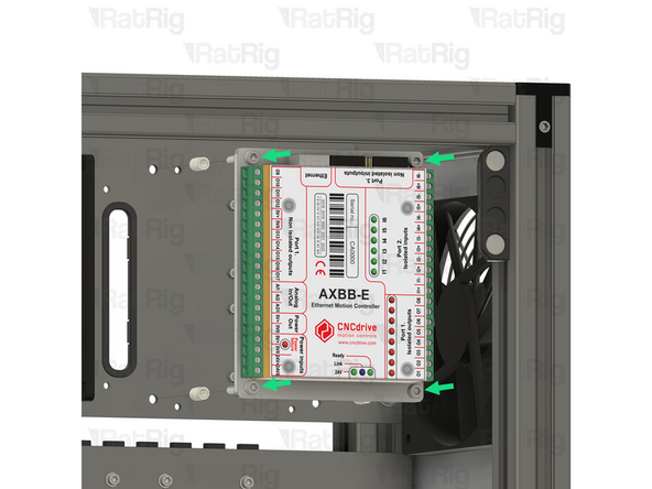
Install an M4x25 screw through each mounting hole on the AXBB-E CNC controller
-
Install a nylon spacer on to each M4x25 screw
-
Align the M4x25 screws with the holes in the panel as shown
-
Keep supporting the AXBB-E CNC controller until the locking hex nuts are installed in the next step
-
-
-
4x M4 locking hex nut
-
Install an M4 locking hex nut on to each of the M4x25 screws and tighten them to secure the AXBB-E CNC controller to the panel
-
-
-
5x M3x6 cap head screw
-
5x M3 washer
-
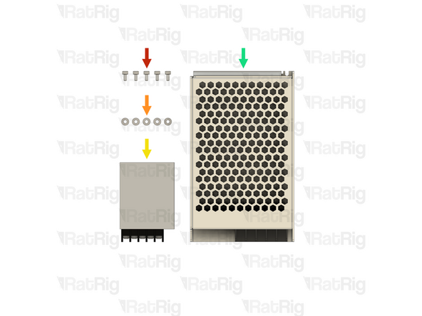
1x Meanwell RS-15-5 5V power supply
-
1x Meanwell RSP-75-24 24V power supply
-
-
-
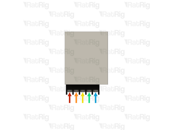
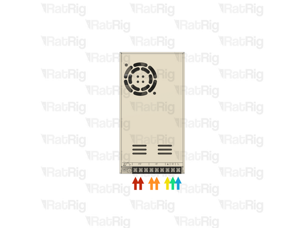
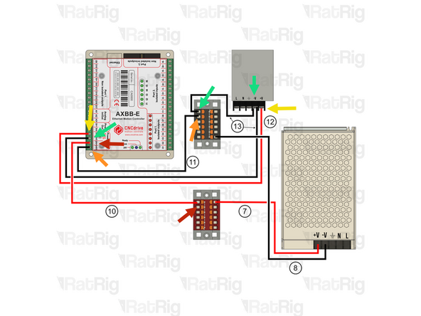
It is recommended to wire the power supply before installing it in the electronics enclosure. Please connect the following wires:
-
XXmm - 18AWG BROWN (A-Fork, B-Ferrule) (XX)
-
XXmm - 18AWG BLUE (A-Fork, B-Ferrule) (XX)
-
XXmm - 18AWG YELLOW/GREEN (A-Fork, B-Ferrule) (XX)
-
2x 400mm - 22AWG BLACK (A-Ferrule, B-Fork) (13) Overlay the two forks in the screw terminal.
-
400mm - 22AWG RED (A-Ferrule, B-Fork) (12)
-
Connect all the wires above to the power supply, using the fork connectors on each wire
-
After insertion, attempt to pull the wire to verify that it is securely attached
-
-
-
Install the component using the designated holes
-
2x M3x6 cap head screw
-
2x M3 washer
-
Install an M3 washer on to each M3x6 screw and insert them into the marked holes
-
-
-
1x Meanwell RS-15-5 5V power supply
-
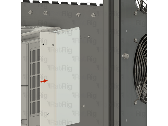
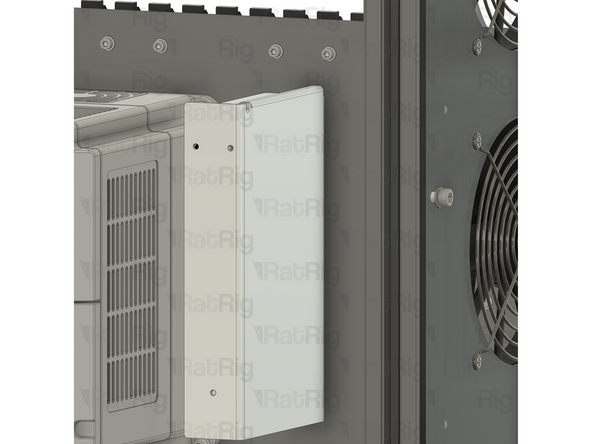
Install the power supply as shown, securing it by screwing the M3x6 screws into the threaded holes on the side of the PSU body
-
Feed all of the power supply wires through the designated slot
-
-
-
It is recommended to wire the power supply before installing it in the electronics enclosure. Please connect the following wires:
-
600mm - 16AWG RED (A-Fork, B-Ferrule) (7)
-
600mm - 22AWG BLACK (A-Fork, B-Ferrule) (8)
-
XXmm - 18AWG YELLOW/GREEN (A-Fork, B-Ferrule) (XX)
-
XXmm - 18AWG BLUE (A-Fork, B-Ferrule) (XX)
-
XXmm - 18AWG BROWN (A-Fork, B-Ferrule) (XX)
-
Connect all the wires above to the power supply, using the fork connectors on each wire
-
After insertion, attempt to pull the wire to verify that it is securely attached
-
-
-
Install the component using the designated holes
-
3x M3x6 cap head screw
-
3x M3 washer
-
Install an M3 washer on to each M3x6 screw and insert them into the marked holes
-
-
-
1x Meanwell RSP-75-24 24V power supply
-
Install the power supply as shown, securing it by screwing the M3x6 screws into the threaded holes on the side of the PSU body
-
Feed all of the power supply wires through the designated slot
-
-
-
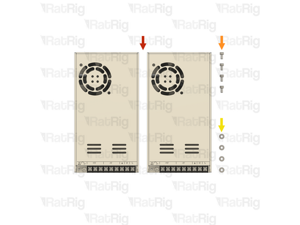
2x Meanwell RSP-320-48 48V power supply
-
4x M4x8 cap head screw
-
4x M4 washer
-
-
-
It is recommended to wire the power supply before installing it in the electronics enclosure. Please connect the following wires:
-
2x 800mm - 16AWG RED (A-Fork, B-Ferrule) (15)
-
2x 800mm - 16AWG BLACK (A-Fork, B-Ferrule) (16)
-
XXmm - 18AWG YELLOW/GREEN (A-Fork, B-Ferrule) (XX)
-
XXmm - 18AWG BLUE (A-Fork, B-Ferrule) (XX)
-
XXmm - 18AWG BROWN (A-Fork, B-Ferrule) (XX)
-
Connect all the wires above to the power supply, using the fork connectors on each wire
-
After insertion, attempt to pull the wire to verify that it is securely attached
-
-
-
Install the component using the designated holes
-
4x M4x8 cap head screw
-
4x M4 washer
-
Install an M4 washer on to each M4x8 screw and insert them into the marked holes
-
-
-
2x Meanwell RSP-320-48 48V power supply
-
Install the power supply as shown, securing it by screwing the M4x8 screws into the threaded holes on the side of the PSU body
-
Repeat to install the second power supply, paying attention to the orientation
-
Feed all of the wires from both power supplies through the designated slot
-
-
-
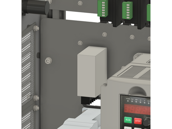
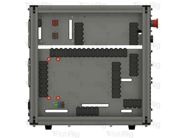
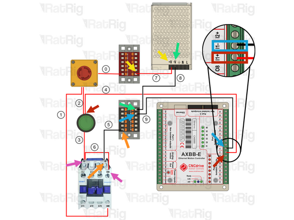
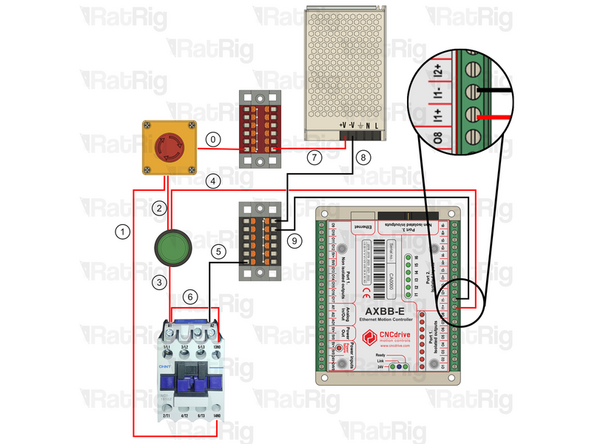
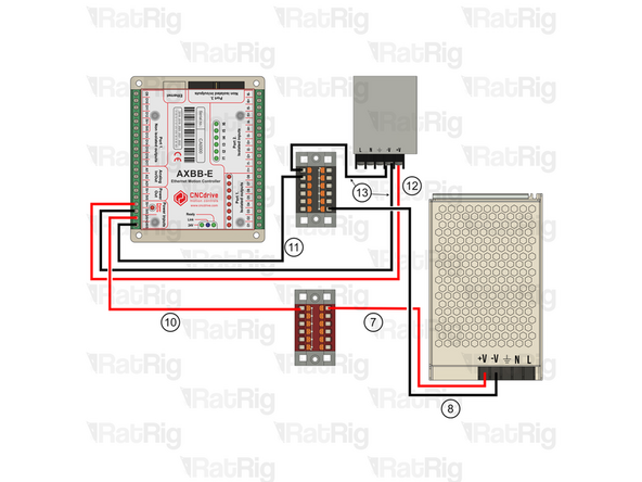
700mm - 16AWG RED (A-Ferrule, B-Ferrule) (4) Connect the wire from the start button (in) to the I1+ terminal on port2 of the AXBB-E
-
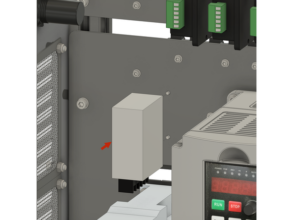
700mm - 16AWG BLACK (A-Ferrule, B-Fork) (5) Connect the ferrule in the Black PTFix block and the fork on the A2 terminal of the contactor.
-
600mm - 16AWG RED (A-Fork, B-Ferrule) (7) Connect the ferrule into the Red PTFix block, the fork end should have been connected to the power supply here.
-
600mm - 16AWG BLACK (A-Fork, B-Ferrule) (8) Connect the ferrule into the Black PTFix block, the fork end should have been connected to the power supply here.
-
150mm - 22AWG BLACK (A-Fork, B-Ferrule) (9) Connect one end of the wire to the Black PTFix block and the other to the I1- terminal on port 2 of the AXBB-E
-
120mm - 16AWG RED (A-Fork, B-Fork) (6) Connect the wire from terminal 13NO on hte contactor to the A1 terminal on the contactor. A1 should have 2 Forks inserted.
-
-
-
Insert wisdom here
-