Introduction
BEFORE STARTING:
Before beginning this guide, you must prepare all the necessary wires for the assembly. Below is a list of the required wires. The following nomenclature will be used: (Wire Length)_(AWG)_(Wire Color)_(A-End Connector)_(B-End Connector)_(ID number).
Use a small piece of tape to label each wire to ensure a smooth assembly process.
- 700mm - 16AWG RED (A-Ferrule, B-Ferrule) (4)
- 700mm - 16AWG BLACK (A-Ferrule, B-Fork) (5)
- 120mm - 16AWG RED (A-Fork, B-Fork) (6)
- 600mm - 16AWG RED (A-Fork, B-Ferrule) (7)
- 600mm - 16AWG BLACK (A-Fork, B-Ferrule) (8)
- 150mm - 22AWG BLACK (A-Fork, B-Ferrule) (9)
- 150mm - 22AWG RED (A-Ferrule, B-Ferrule) (10)
- 150mm - 22AWG BLACK (A-Ferrule, B-Ferrule) (11)
- 500mm - 22AWG RED (A-Ferrule, B-Fork) (12)
- 2x 500mm - 22AWG BLACK (A-Ferrule, B-Fork) (13)
- 4x 550mm - Multicore 3 Conductor - 24AWG BLACK (A-(3x)Ferrule, B-(3x)Ferrule) (14)
- 4x 800mm - 16AWG RED (A-Fork, B-Ferrule) (15)
- 4x 800mm - 16AWG BLACK (A-Fork, B-Ferrule) (16)
- 4x 30mm - 22AWG BLACK (A-Ferrule, B-Ferrule) (17)
- 3x 100mm - 22AWG RED (A-Ferrule, B-Ferrule) (18)
- 900mm - Multicore 2 Conductor - 24AWG (A-2xFerrule, B-2xFerrule) (19)
- 100mm - 16AWG BLACK (A-Ferrule, B-Ferrule) (20)
-
-
The DM542T stepper drivers allow current and micro-stepping control, resulting in a vast range of configurations.
-
Adjust the switches on the drivers for each stepper motor
-
Depressing switches 1 and 2 while simultaneously elevating switch 3 establishes a current of 2.69 amperes, marginally below the rated current for the stepper motors. This configuration is designed to enhance performance and extend the operational lifespan of the components.
-
The upwwards positioning of switch 4 ensures that only half of the designated current is provided to the stepper motors when they are at a standstill, thus preventing the potential for overheating in both the stepper motors and the associated drivers.
-
STRONGHOLD PRO Elevating Switches 5 and 6 with the downward orientation of Switches 7 and 8 configures the pulse/revolution rate to 1600, in conjunction with the ball screws, this specific arrangement ensures that the axis traverses a distance of 1mm for each full revolution accomplished by the stepper motor, with the exception of the Z axis.
-
Repeat for the other DM542T stepper drivers
-
-
-
There is a small switch on top of the DM542T stepper driver, ensure it is set to 5V as the AXBB signal is 5V.
-
Repeat for the other DM542T stepper drivers
-
-
-
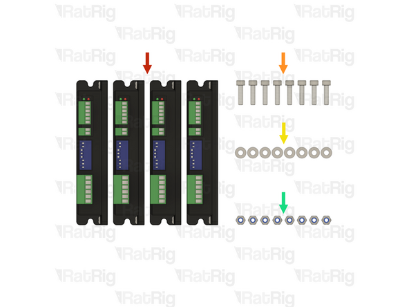
4x Stepper driver - OMC DM542T
-
8x M4x16 cap head screw
-
8x M4 washer
-
8x M4 locking hex nut
-
-
-
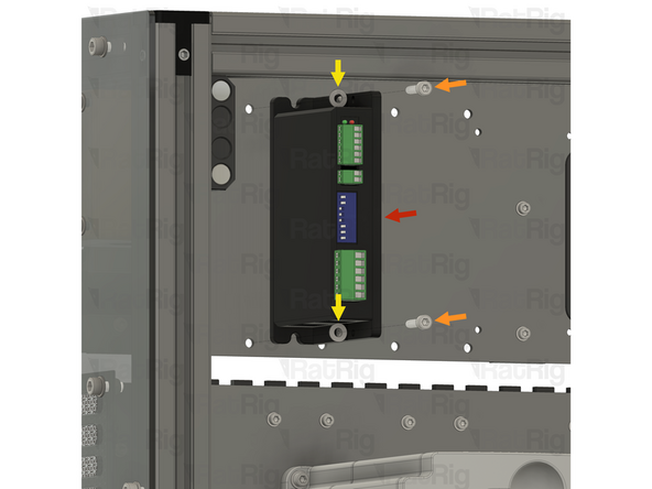
1x Stepper driver - OMC DM542T
-
2x M4x16 cap head screw
-
2x M4 washer
-
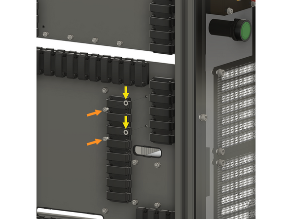
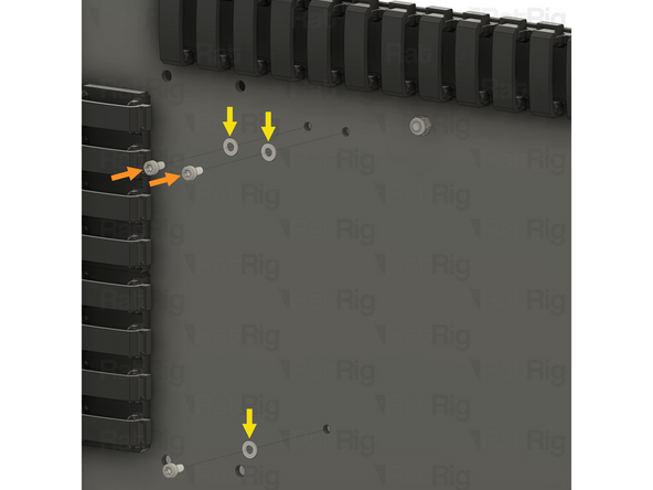
Install an M4 washer on to each M4x16 screw
-
Align the stepper driver with the holes on the panel, and insert an M4x16 screw through the stepper driver and panel as shown
-
Keep supporting the stepper driver until the locking hex nuts are installed in the next step
-
-
-
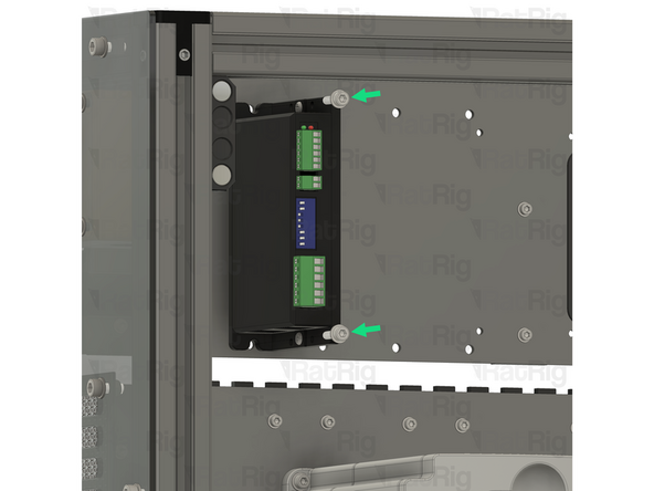
2x M4 locking hex nut
-
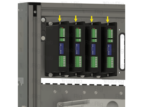
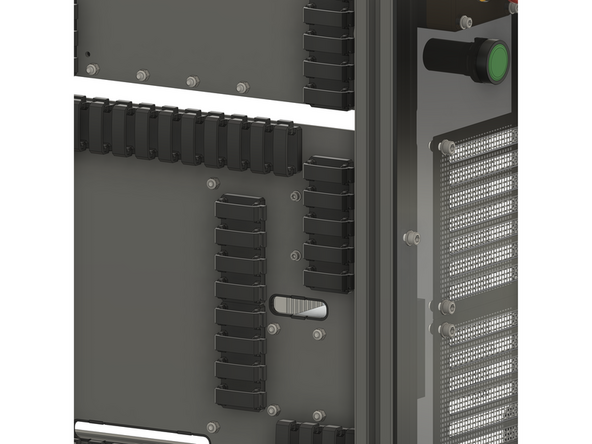
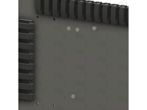
Install an M4 locking hex nut on to each of the M4x16 screws and tighten them to secure the stepper driver to the panel
-
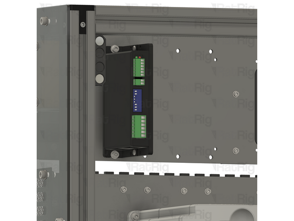
Repeat the previous step, and this step, to install the remaining 3 stepper drivers as shown
-
-
-
1x CNCDrive AXBB-E CNC controller
-
4x Spacer - Nylon - 4.2x6.3x10mm
-
4x M4x25 cap head screw
-
4x M4 locking hex nut
-
-
-
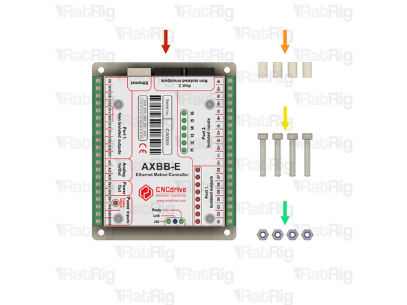
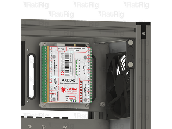
1x CNCDrive AXBB-E CNC controller
-
4x Spacer - Nylon - 4.2x6.3x10mm
-
4x M4x25 cap head screw
-
Install an M4x25 screw through each mounting hole on the AXBB-E CNC controller
-
Install a nylon spacer on to each M4x25 screw
-
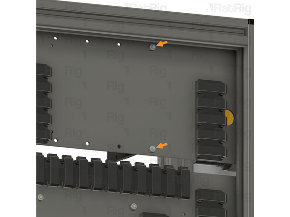
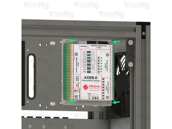
Align the M4x25 screws with the holes in the panel as shown
-
Keep supporting the AXBB-E CNC controller until the locking hex nuts are installed in the next step
-
-
-
4x M4 locking hex nut
-
Install an M4 locking hex nut on to each of the M4x25 screws and tighten them to secure the AXBB-E CNC controller to the panel
-
-
-
5x M3x6 cap head screw
-
5x M3 washer
-
1x Meanwell RS-15-5 5V power supply
-
1x Meanwell RSP-75-24 24V power supply
-
-
-
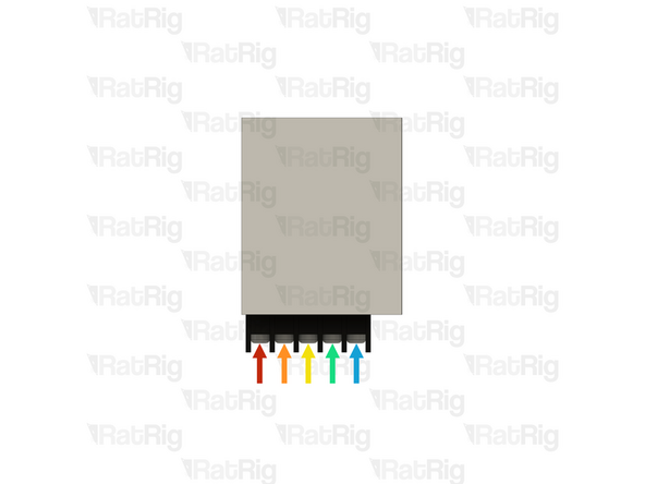
It is recommended to wire the power supply before installing it in the electronics enclosure. Please connect the following wires:
-
XXmm - 18AWG BROWN (A-Fork, B-Ferrule) (XX)
-
XXmm - 18AWG BLUE (A-Fork, B-Ferrule) (XX)
-
XXmm - 18AWG YELLOW/GREEN (A-Fork, B-Ferrule) (XX)
-
2x 400mm - 22AWG BLACK (A-Ferrule, B-Fork) (13) Overlay the two forks in the screw terminal.
-
400mm - 22AWG RED (A-Ferrule, B-Fork) (12)
-
Connect all the wires above to the power supply, using the fork connectors on each wire
-
After insertion, attempt to pull the wire to verify that it is securely attached
-
-
-
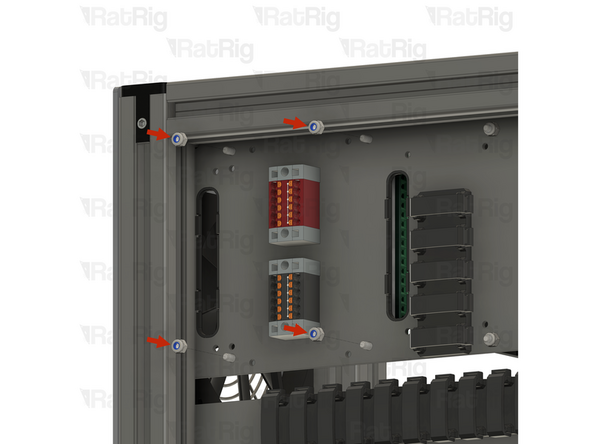
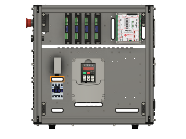
Install the component using the designated holes
-
2x M3x6 cap head screw
-
2x M3 washer
-
Install an M3 washer on to each M3x6 screw and insert them into the marked holes
-
-
-
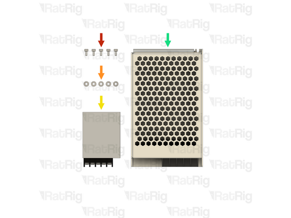
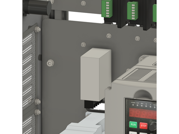
1x Meanwell RS-15-5 5V power supply
-
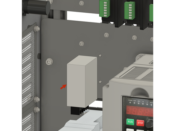
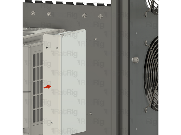
Install the power supply as shown, securing it by screwing the M3x6 screws into the threaded holes on the side of the PSU body
-
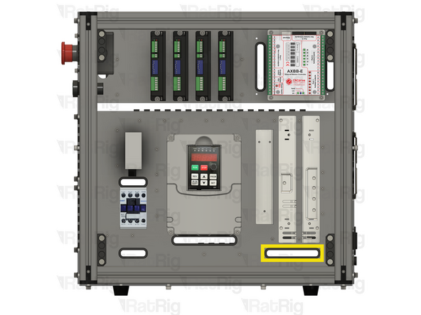
Feed all of the power supply wires through the designated slot
-
-
-
It is recommended to wire the power supply before installing it in the electronics enclosure. Please connect the following wires:
-
600mm - 16AWG RED (A-Fork, B-Ferrule) (7)
-
600mm - 22AWG BLACK (A-Fork, B-Ferrule) (8)
-
XXmm - 18AWG YELLOW/GREEN (A-Fork, B-Ferrule) (XX)
-
XXmm - 18AWG BLUE (A-Fork, B-Ferrule) (XX)
-
XXmm - 18AWG BROWN (A-Fork, B-Ferrule) (XX)
-
Connect all the wires above to the power supply, using the fork connectors on each wire
-
After insertion, attempt to pull the wire to verify that it is securely attached
-
-
-
Install the component using the designated holes
-
3x M3x6 cap head screw
-
3x M3 washer
-
Install an M3 washer on to each M3x6 screw and insert them into the marked holes
-
-
-
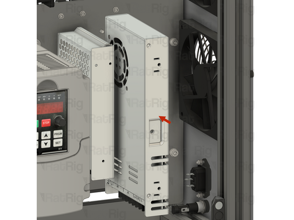
1x Meanwell RSP-75-24 24V power supply
-
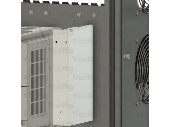
Install the power supply as shown, securing it by screwing the M3x6 screws into the threaded holes on the side of the PSU body
-
Feed all of the power supply wires through the designated slot
-
-
-
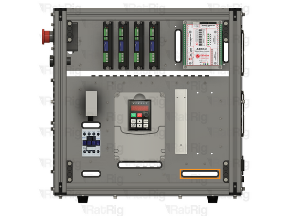
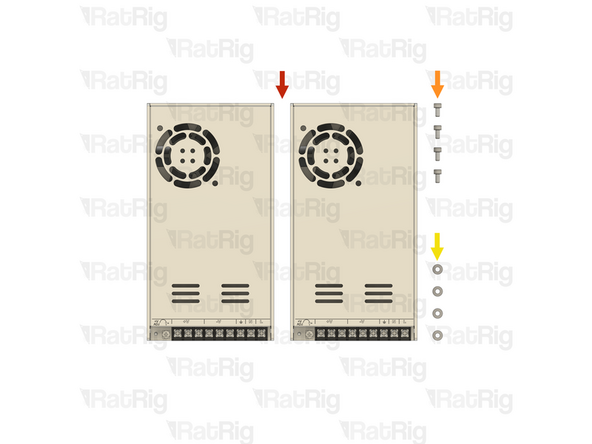
2x Meanwell RSP-320-48 48V power supply
-
4x M4x8 cap head screw
-
4x M4 washer
-
-
-
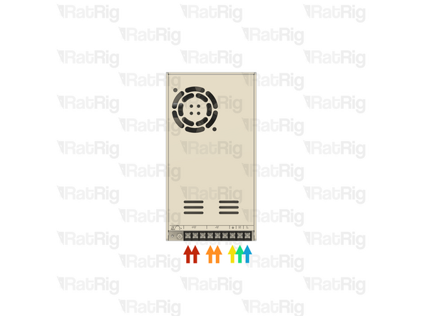
It is recommended to wire the power supply before installing it in the electronics enclosure. Please connect the following wires:
-
2x 800mm - 16AWG RED (A-Fork, B-Ferrule) (15)
-
2x 800mm - 16AWG BLACK (A-Fork, B-Ferrule) (16)
-
XXmm - 18AWG YELLOW/GREEN (A-Fork, B-Ferrule) (XX)
-
XXmm - 18AWG BLUE (A-Fork, B-Ferrule) (XX)
-
XXmm - 18AWG BROWN (A-Fork, B-Ferrule) (XX)
-
Connect all the wires above to the power supply, using the fork connectors on each wire
-
After insertion, attempt to pull the wire to verify that it is securely attached
-
-
-
Install the component using the designated holes
-
4x M4x8 cap head screw
-
4x M4 washer
-
Install an M4 washer on to each M4x8 screw and insert them into the marked holes
-
-
-
2x Meanwell RSP-320-48 48V power supply
-
Install the power supply as shown, securing it by screwing the M4x8 screws into the threaded holes on the side of the PSU body
-
Repeat to install the second power supply, paying attention to the orientation
-
Feed all of the wires from both power supplies through the designated slot
-
-
-
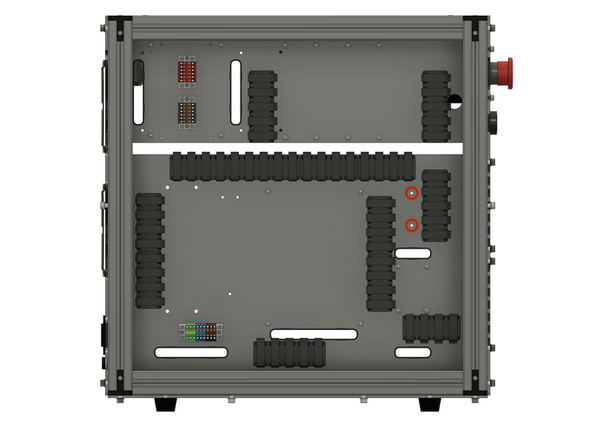
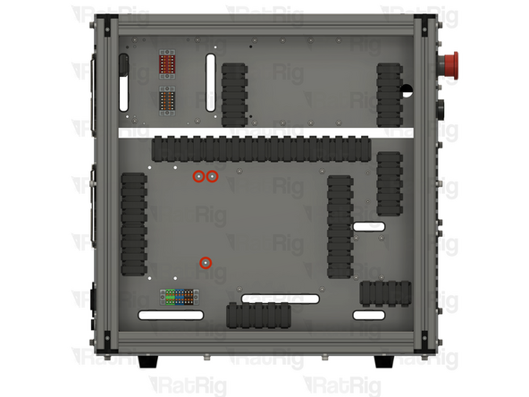
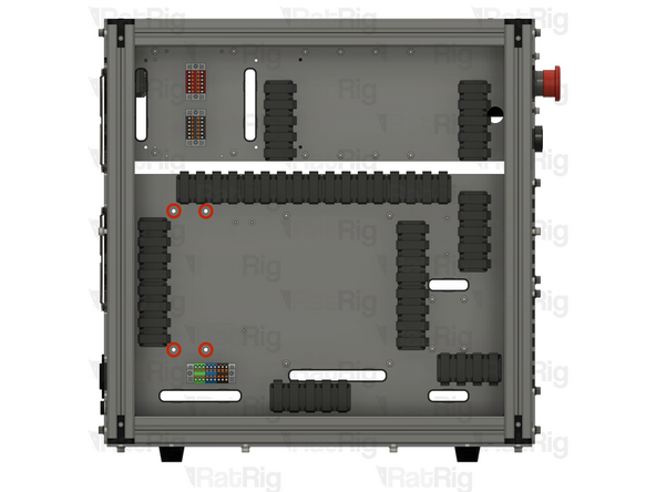
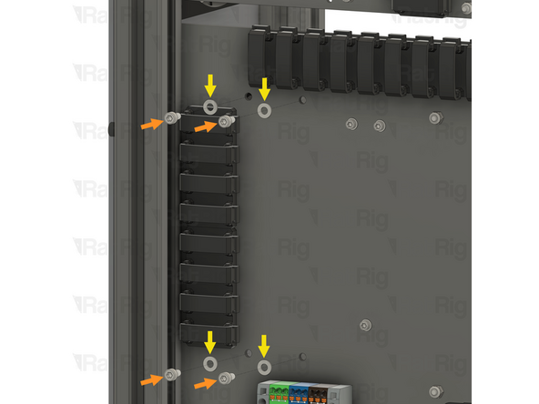
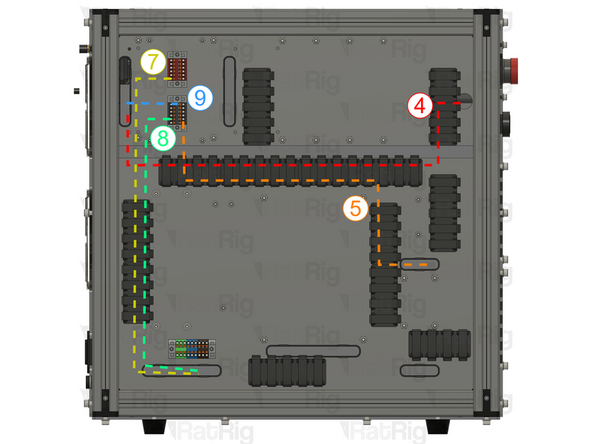
Route the wires on the back of the enclosure as shown.
-
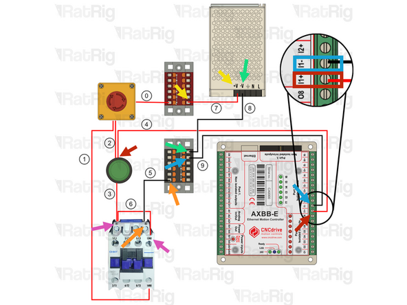
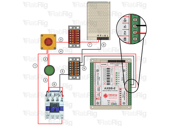
700mm - 16AWG RED (A-Ferrule, B-Ferrule) (4) Connect the wire from the start button (in) to the I1+ terminal on port2 of the AXBB-E
-
700mm - 16AWG BLACK (A-Ferrule, B-Fork) (5) Connect the ferrule in the Black PTFix block and the fork on the A2 terminal of the contactor.
-
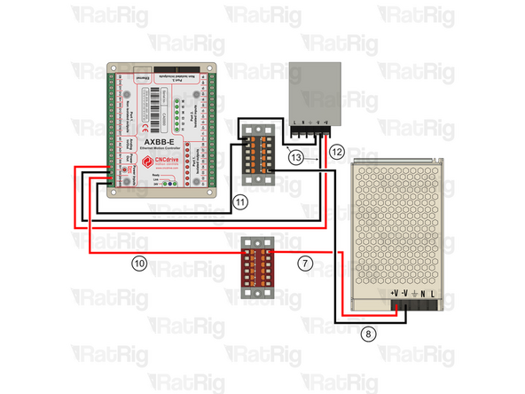
600mm - 16AWG RED (A-Fork, B-Ferrule) (7) Connect the ferrule into the Red PTFix block, the fork end should have been connected to the power supply here.
-
600mm - 16AWG BLACK (A-Fork, B-Ferrule) (8) Connect the ferrule into the Black PTFix block, the fork end should have been connected to the power supply here.
-
150mm - 22AWG BLACK (A-Fork, B-Ferrule) (9) Connect one end of the wire to the Black PTFix block and the other to the I1- terminal on port 2 of the AXBB-E
-
120mm - 16AWG RED (A-Fork, B-Fork) (6) Connect the wire from terminal 13NO on hte contactor to the A1 terminal on the contactor. A1 should have 2 Forks inserted.
-
-
-
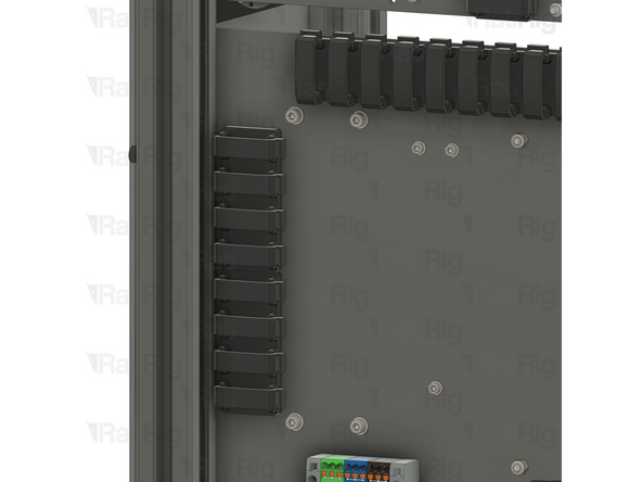
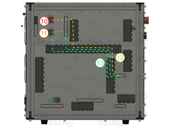
Route the wires on the back of the enclosure as shown.
-
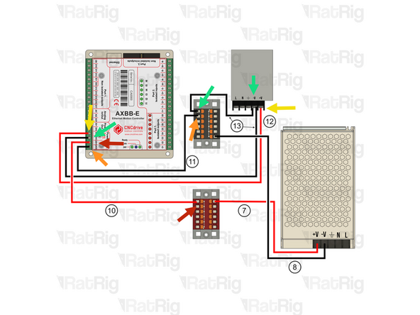
150mm - 22AWG RED (A-Ferrule, B-Ferrule) (10) Connect the wire from the Red PTFix block to the +24V input on the AXBB-E
-
150mm - 22AWG BLACK (A-Ferrule, B-Ferrule) (11) Connect the wire from the Black PTFix block to the -24V input on the AXBB-E
-
500mm - 22AWG RED (A-Ferrule, B-Fork) (12) Connect the fork end to the +V terminal on the 5V power supply and the ferrule end in the 5V+ terminal on the AXBB-E.
-
2x 500mm - 22AWG BLACK (A-Ferrule, B-Fork) (13) Connect the wire from the -V terminal on the 5V Power supply using the fork connector and connect the ferrule in the Black PTFix block. The second (13) wire should be connected from the -V terminal on the 5V Power supply using the fork connector and then connected to the AXBB-E 5V0 terminal
-
-
-
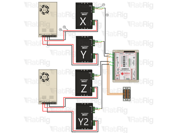
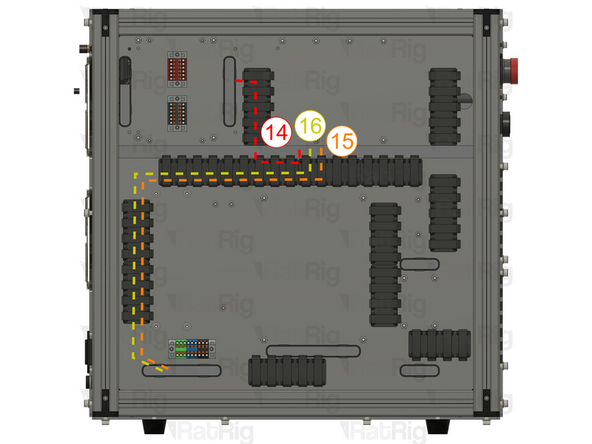
Ignore Y2 if you are wiring a Rat Rig Mill. Repeat the Steps to connect all drivers.
-
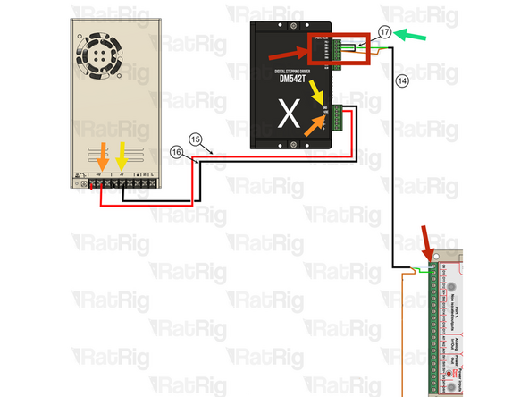
4x 550mm - Multicore 3 Conductor - 24AWG BLACK (A-(3x)Ferrule, B-(3x)Ferrule) (14)
-
DRIVER SIDE: Connect the white wire to PUL+ , the green wire to DIR+ and the brown wire to DIR-
-
AXBB-E Side: Connect the white wire to 09 , the green wire to 010 and the brown wire to the Black PTFix Block
-
Follow the order and connect stepper Y( PUL+ to 011, DIR+ to 012), then Z( PUL+ to 013, DIR+ to 014), Lastly Y2( PUL+ to 015, DIR+ to 016)
-
4x 30mm - 22AWG BLACK (A-Ferrule, B-Ferrule) (17) To jump DIR- with PUL-
-
4x 800mm - 16AWG RED (A-Fork, B-Ferrule) (15) The Fork terminals should be already wired to the 48V Power supplies here. Then connect it to +VDC on the driver.
-
4x 800mm - 16AWG BLACK (A-Fork, B-Ferrule) (16) The Fork terminals should be already wired to the 48V Power supplies here. Then connect it to GND on the driver.
-
-
-
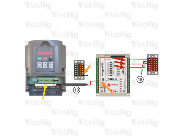
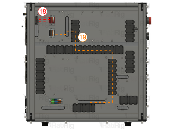
3x 100mm - 22AWG RED (A-Ferrule, B-Ferrule) (18) Connect one end to the Red PTFix block and the other to I6+ terminal on port 2 of the AXBB-E.
-
Repeat the previous Step and connect I5+ and I4+ the the Red PTFix Block.
-
900mm - Multicore 2 Conductor - 24AWG (A-2xFerrule, B-2xFerrule) (19) Connect the 2 wire cable to from the VFD and AXBB-E
-
Use the Red wire for the VI terminal on the VFD and A01 analog input on the AXBB-E
-
Use the Black wire for the black PTFix Block and ACM terminal on the VFD.
-
100mm - 16AWG BLACK (A-Ferrule, B-Ferrule) (20) Connect the FOR terminal with the DCM terminal on the VFD
-
-
-
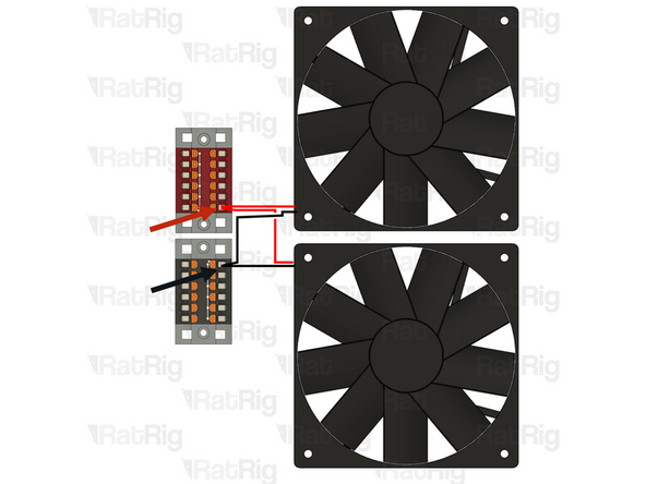
Cut the JST connectors on the cooling fans and crimp both red wires in the same ferrule, then insert it into the Red PTFix Block.
-
Cut the JST connectors on the cooling fans and crimp both black wires in the same ferrule, then insert it into the Black PTFix Block.
-