
Steps
13
- 04. CoreXY Idler Assemblies 13 steps

User-Contributed Guide
This guide is not managed by the site's staff.
Quiz
0
-
-
2x idler_plate
-
1x xy_idler_right_3.1 Printed Part
-
1x xy_idler_left_3.1 Printed Part
-
4x M6x14 Countersink Screw
-
10x M6x12 Cap Head Screw
-
14x 3030 Drop-in T-Nut - M6
-
2x M5 Nylon Locking Hex Nut
-
-
-
idler_plate
-
Make sure the idler plate is oriented as shown
-
M6x12 Cap Head Screw
-
3030 Drop-in T-Nut - M6
-
Loosely thread a 3030 T-Nut onto each of the M6x12 screws. Do not tighten them at this point
-
Set this assembly aside until Step 6
-
-
-
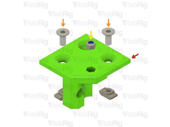
xy_idler_left_3.1 Printed Part
-
Each xy_idler printed part is stamped with "L" or "R", indicating left or right
-
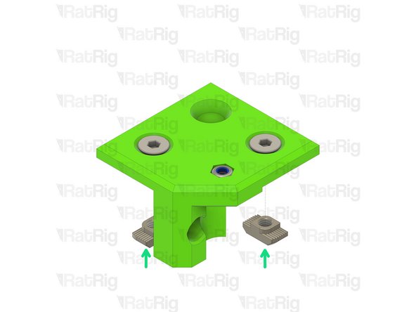
M6x14 Countersink Screw
-
M5 Nylon Locking Hex Nut
-
3030 Drop-in T-Nut - M6
-
Loosely thread a 3030 T-Nut onto each of the M6x14 screws. Do not tighten them at this point.
-
Set this assembly aside until Step 8
-
-
-
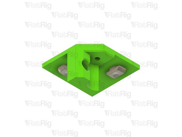
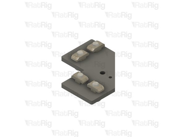
Repeat the previous two steps for the right CoreXY idler
-
Make sure the idler plate is oriented as shown when assembling the right side
-
Once both assemblies are complete, place them aside until Steps 10 & 11
-
-
-
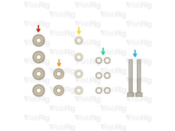
4x F695ZZ Ball Bearing
-
2x 695ZZ Ball Bearing
-
4x 6mm Aluminium Spacer
-
6x Mini Precision Shim
-
2x M5x40 Cap Head Screw
-
-
-
V-Core 3.1 Frame Assembly - Front Left Corner
-
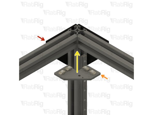
Assembly from Step 2
-
Install the left idler_plate assembly to the V-Core 3.1 frame as shown
-
Tighten the four M6x12 screws to secure the idler_plate assembly
-
Make sure the plate is fully seated against the 3030 extrusion before tightening the M6x12 screws
-
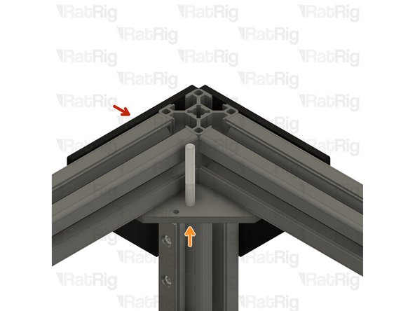
Insert one M5x40 Cap Head Screw into the idler_plate in preparation for the next step
-
-
-
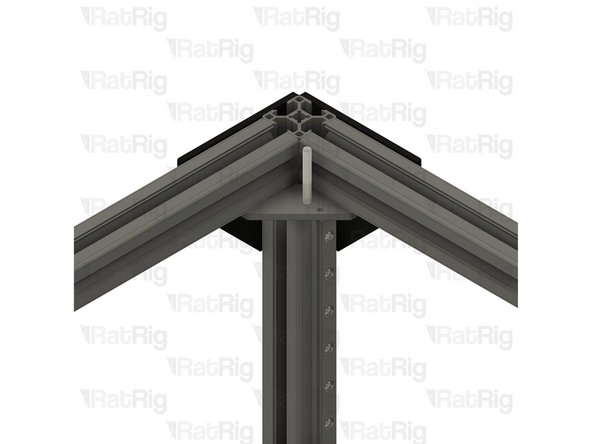
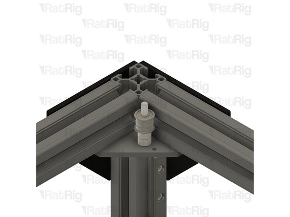
M5x40 Cap Head Screw
-
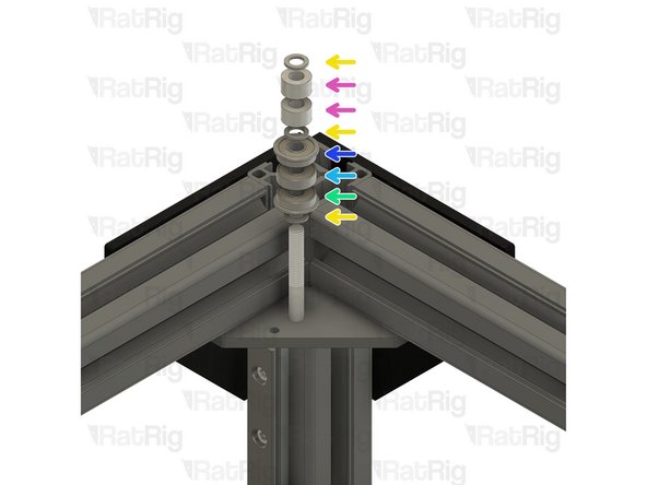
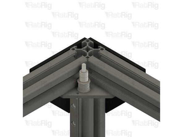
Install the following components in the order shown in the image
-
Mini Precision Shim
-
6mm Aluminium Spacer
-
F695ZZ Ball Bearing (Flange at the bottom)
-
695ZZ Ball Bearing
-
F695ZZ Ball Bearing (Flange at the top)
-
-
-
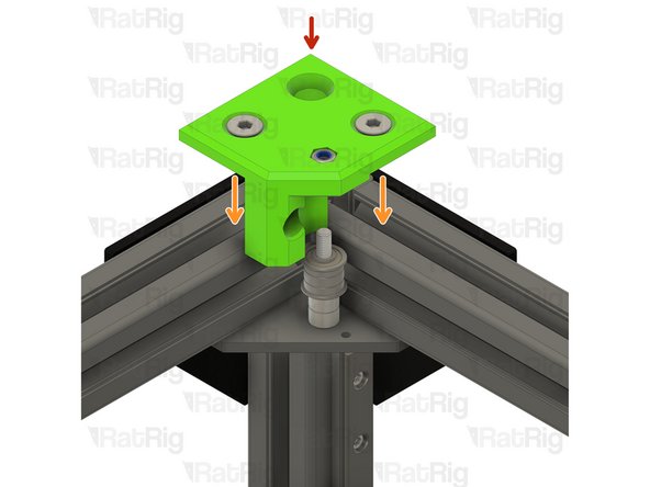
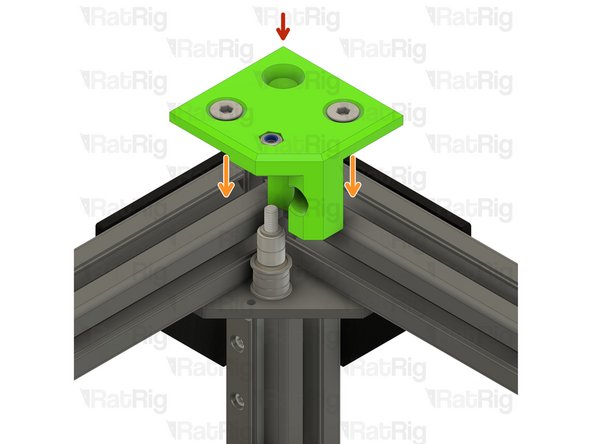
Assembly from Step 3
-
Install the left CoreXY idler onto the frame as shown
-
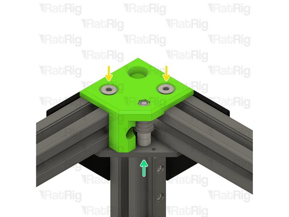
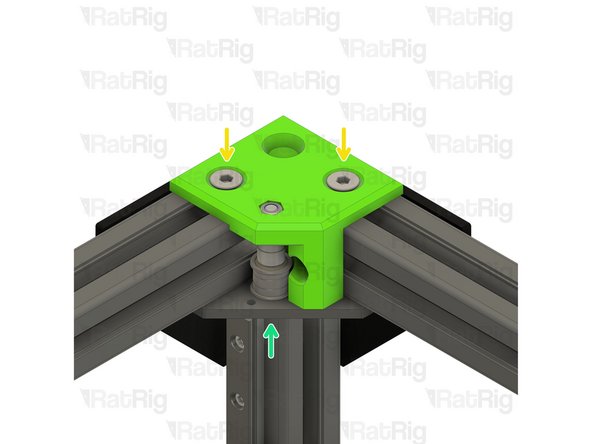
Tighten the two marked M6x14 screws to secure the CoreXY idler to the frame
-
Take care not to over tighten the M6x14 screws as you can damage the printed part
-
Tighten the M5x40 screw to secure the bearing stack into the CoreXY idler
-
-
-
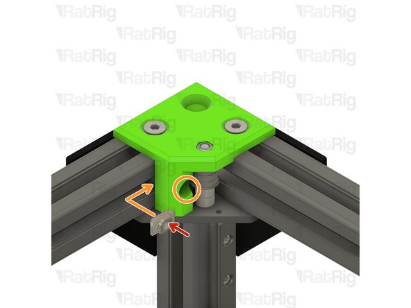
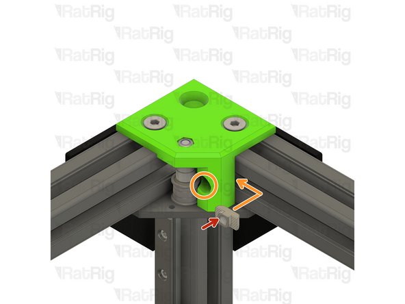
3030 Drop-in T-Nut - M6
-
Place the 3030 T-nut into the extrusion channel and slide it under the CoreXY idler as shown. Position the T-nut so that you are able to see it though the marked hole
-
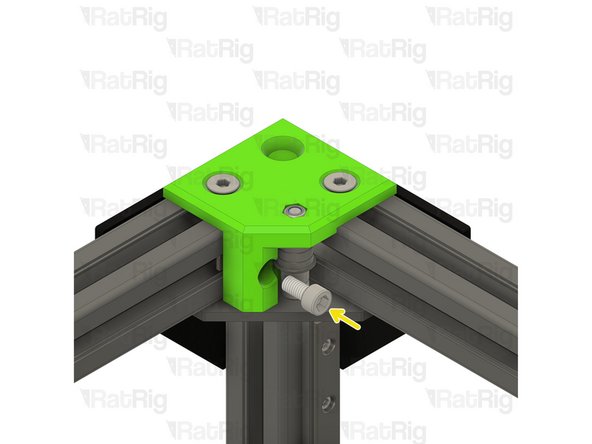
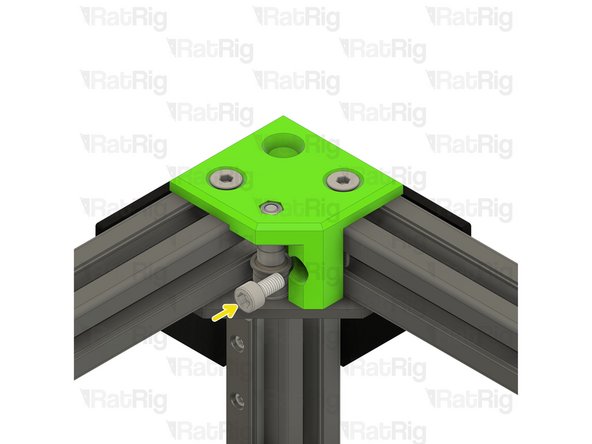
M6x12 Cap Head Screw
-
Insert the M6x12 screw as shown and secure it into the previously positioned 3030 T-nut
-
-
-
V-Core 3.1 Frame Assembly - Front Right Corner
-
Repeat Step 6 to install the right CoreXY idler plate to the frame
-
Install the following components in the order shown in the image
-
Mini Precision Shim
-
F695ZZ Ball Bearing (Flange at the bottom)
-
695ZZ Ball Bearing
-
F695ZZ Ball Bearing (Flange at the top)
-
6mm Aluminium Spacer
-
-
-
Assembly from Step 4
-
Install the right CoreXY idler onto the frame as shown
-
Tighten the two marked M6x14 screws to secure the CoreXY idler to the frame
-
Take care not to over tighten the M6x14 screws as you can damage the printed part
-
Tighten the M5x40 screw to secure the bearing stack into the CoreXY idler
-
-
-
3030 Drop-in T-Nut - M6
-
Place the 3030 T-nut into the extrusion channel and slide it under the CoreXY idler as shown. Position the T-nut so that you are able to see it though the marked hole
-
M6x12 Cap Head Screw
-
Insert the M6x12 screw as shown and secure it into the previously positioned 3030 T-nut
-


Cancel: I did not complete this guide.
33 other people completed this guide.