
Steps
21
- 05. CoreXY Motor Assemblies 21 steps

User-Contributed Guide
This guide is not managed by the site's staff.
Quiz
0
-
-
2x motor_plate
-
1x motor_support_left Printed Part
-
1x motor_support_right Printed Part
-
8x M6x12 Cap Head Screw
-
8x 3030 Drop-in T-Nut - M6
-
4x M5x40 Cap Head Screw
-
-
-
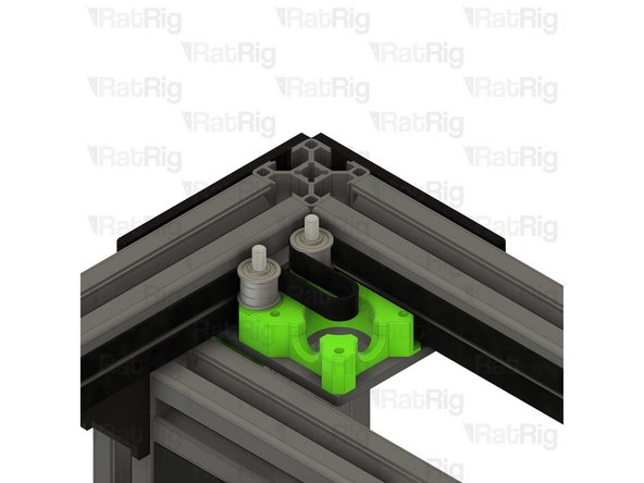
motor_plate
-
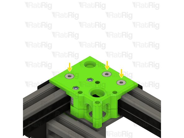
Make sure the motor plates are oriented as shown
-
motor_support_left Printed Part
-
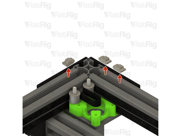
M6x12 Cap Head Screw
-
3030 Drop-in T-Nut - M6
-
Loosely thread a 3030 T-Nut onto each of the M6x12 screws. Do not tighten them at this point.
-
motor_support_right Printed Part
-
Set the right motor plate assembly, and two M5x40 Cap Head Screws, aside until Step 12
-
-
-
V-Core 3.1 Frame Assembly - Rear Left Corner
-
Left motor_plate assembly from Step 2
-
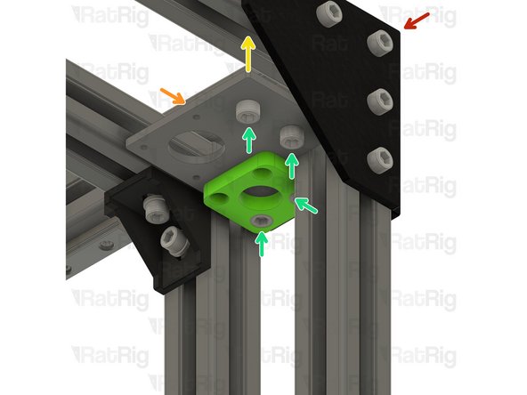
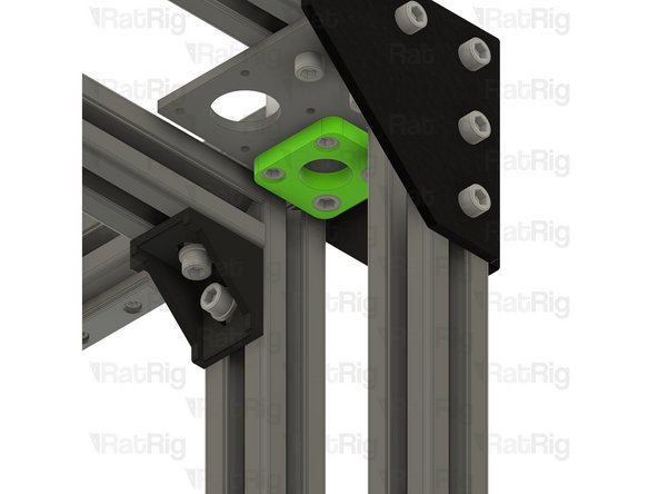
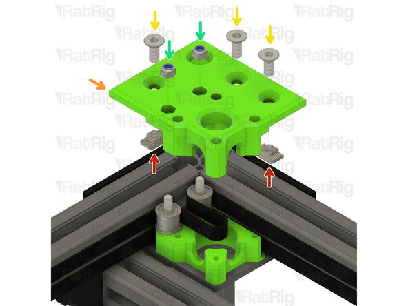
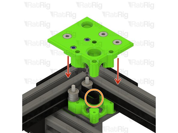
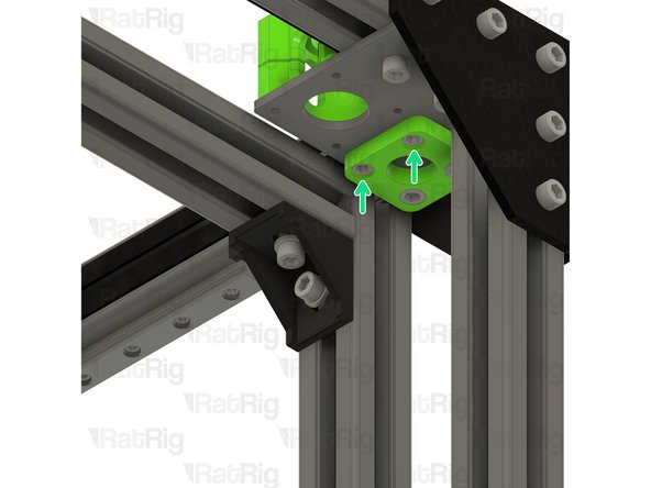
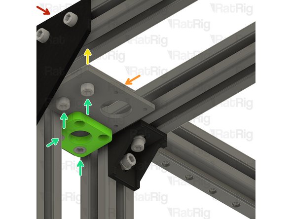
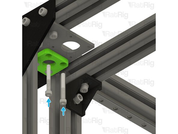
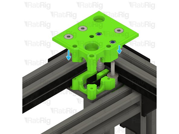
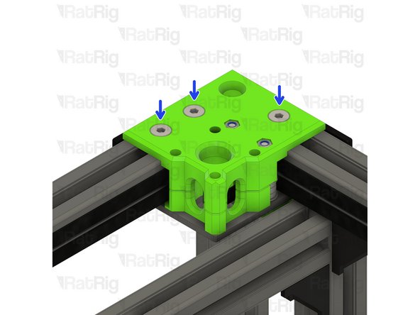
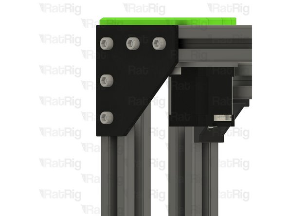
Install the left motor_plate assembly to the V-Core 3.1 frame as shown
-
Tighten the four M6x12 screws to secure the motor_plate assembly to the frame
-
Make sure the plate is fully seated against the 3030 extrusion before tightening the M6x12 screws
-
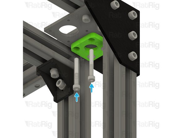
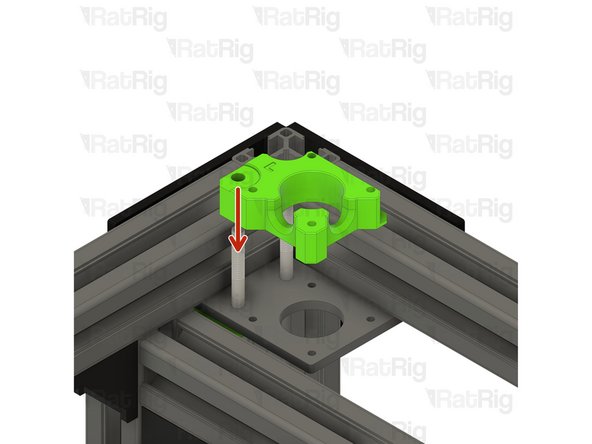
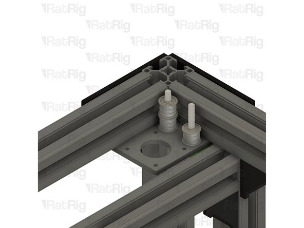
Insert two M5x40 screws into the motor_plate, as shown, in preparation for Step 5
-
-
-
3x M6x14 Countersink Screw
-
3x 3030 Drop-in T-Nut - M6
-
1x xy_motor_cage_bottom_left_3.1 Printed Part
-
1x xy_motor_cage_top_left_3.1 Printed Part
-
6x F695ZZ Ball Bearing
-
3x 695ZZ Ball Bearing
-
5x Mini Precision Shim
-
2x M5 Nylon Locking Hex Nut
-
-
-
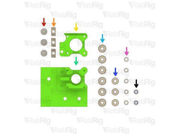
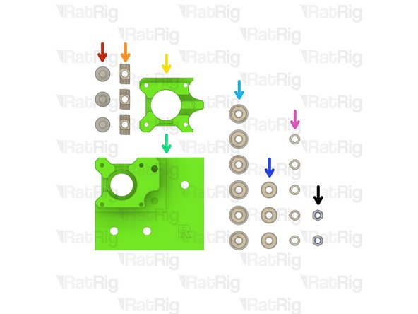
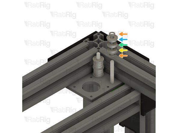
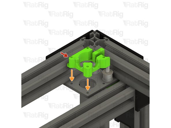
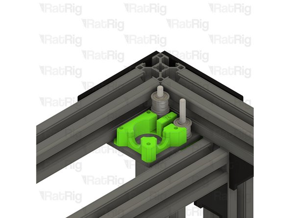
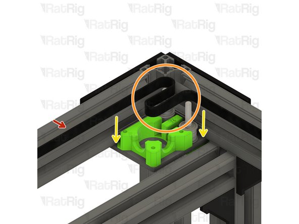
Install the xy_motor_cage_bottom_left printed part as shown
-
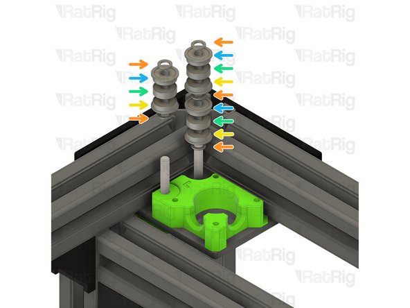
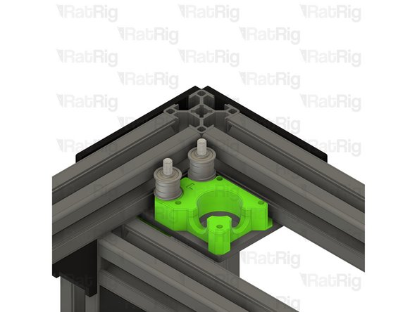
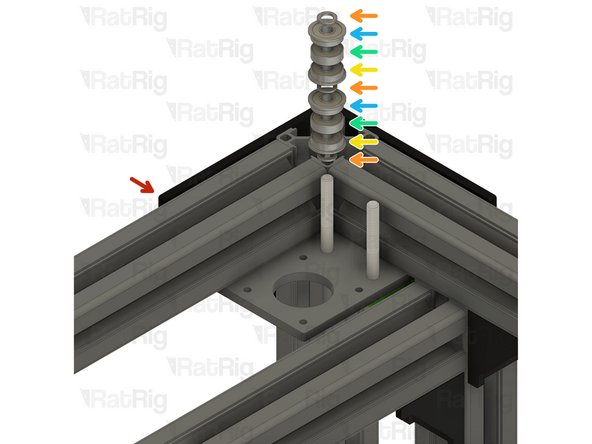
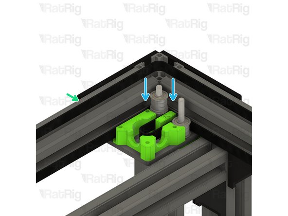
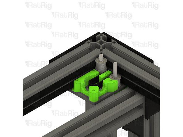
Install the following components in the order shown in the image:
-
Mini Precision Shim
-
F695ZZ Ball Bearing (Flange at the bottom)
-
695ZZ Ball Bearing
-
F695ZZ Ball Bearing (Flange at the top)
-
-
-
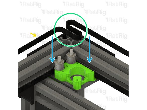
Proper installation of the belt is very important, failure to follow the instructions can lead to damage of the belt
-
The CoreXY belt is provided in one continuous length. Unroll the belt and cut it in half to give you two belts of the same length
-
Position one half of the belt so that the toothed side faces the frame, and the smooth side faces the bearing stacks
-
Slot this half to the bottom of the CoreXY motor assembly, it should align with the bottom bearing stack
-
Take the other half of the CoreXY belt. Again, position the belt so that the toothed side faces the frame and the smooth side faces the bearing stacks
-
Form a loop as shown, this will be used to engage with the NEMA17 motor pulley
-
Position the upper belt as shown
-
Make sure that both belts match the third image before proceeding
-
-
-
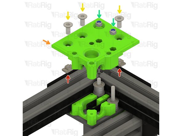
3030 Drop-in T-Nut - M6
-
xy_motor_cage_top_left_3.1 Printed Part
-
M6x14 Countersink Screw
-
Loosely thread a 3030 T-Nut onto each of the M6x14 screws. Do not tighten them at this point.
-
M5 Nylon Locking Hex Nut
-
-
-
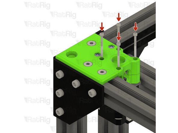
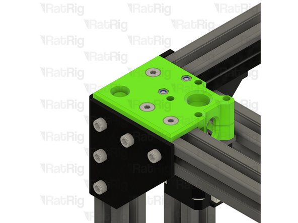
Install the xy_motor_cage_left_top assembly onto the frame as shown
-
Make sure the belt loop, created in Step 6, remains in the position shown
-
Tighten the three marked M6x14 screws to secure the CoreXY motor cage top to the frame
-
Take care not to over tighten the M6x14 screws as you can damage the printed part
-
Tighten the M5x40 screws to secure the bearing stacks into the CoreXY motor cage top
-
-
-
1x 20 Tooth 2GT Timing Pulley for 9mm Belt
-
1x 48mm NEMA17 Stepper Motor
-
4x M3x35 Cap Head Screw
-
-
-
20 Tooth 2GT Timing Pulley for 9mm Belt
-
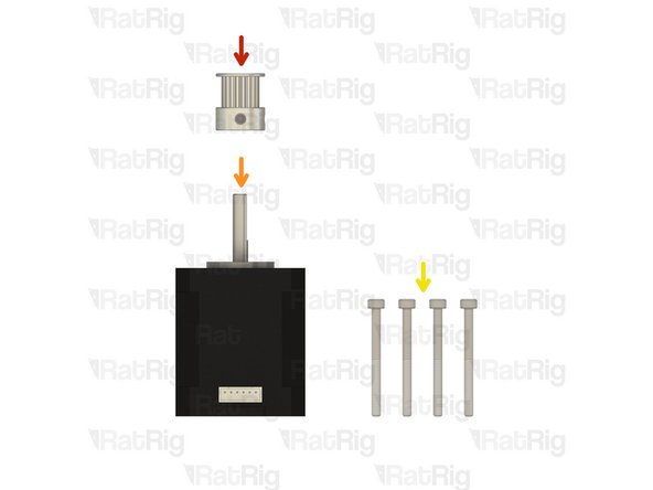
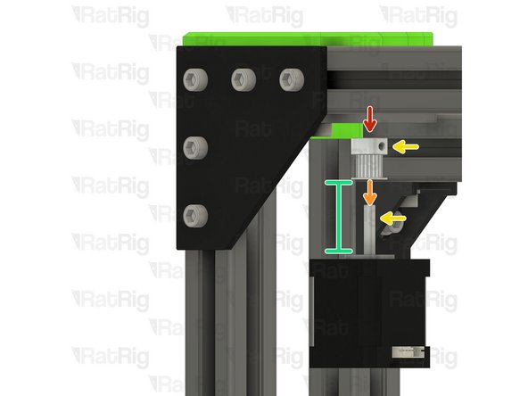
Install the timing pulley onto the NEMA17 shaft, oriented as shown
-
Align one of the M3 grub screws on the timing pulley so that it will tighten against the flat on the NEMA17 shaft
-
Position the timing pulley so the marked gap is 9.5mm
-
Slightly tighten one of the M3 grub screws to hold the timing pulley in position for now
-
The timing pulley will be aligned and fully secured in the next step
-
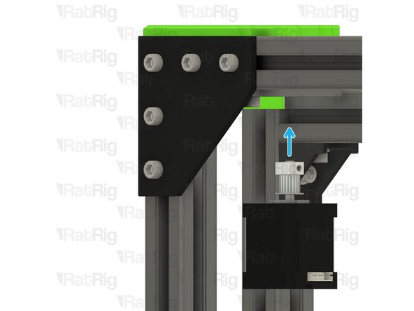
Position the NEMA17 motor up and into the motor cage from below, it will be secured in the next step
-
-
-
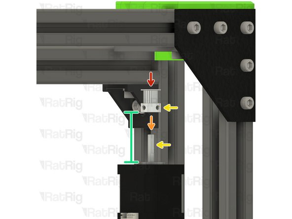
Insert the M3x35 screws into the xy_motor_cage_left_top as shown, and fasten them to secure the NEMA17 motor to the mount
-
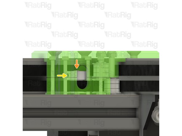
Check the alignment of the timing pulley, the belt should be on the middle of the pulley as shown
-
Adjust the pulley up or down if required to make sure the belt is in the middle of the pulley
-
Fasten both M3 grub screws to securely mount the timing pulley to the NEMA17 motor shaft
-
-
-
V-Core 3.1 Frame Assembly - Rear Right Corner
-
Right motor_plate assembly from Step 2
-
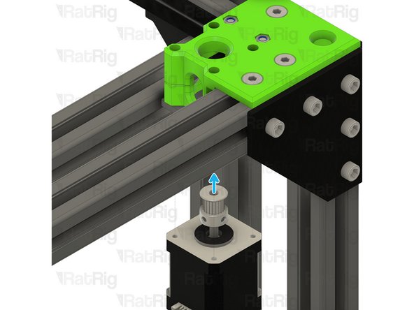
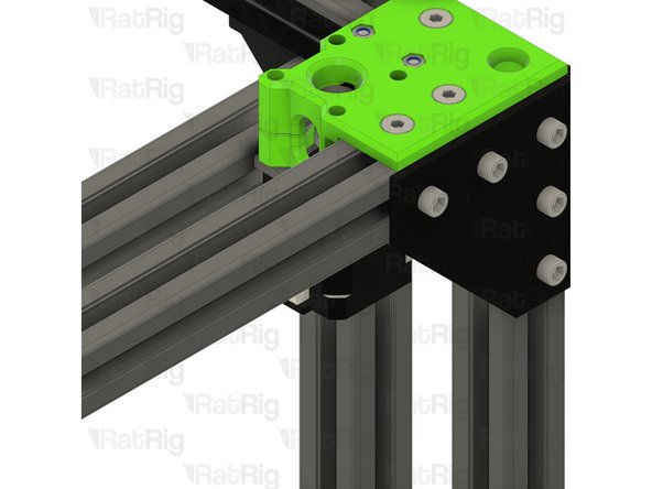
Install the right motor_plate assembly to the V-Core 3.1 frame as shown
-
Tighten the four M6x12 screws to secure the motor_plate assembly to the frame
-
Make sure the plate is fully seated against the 3030 extrusion before tightening the M6x12 screws
-
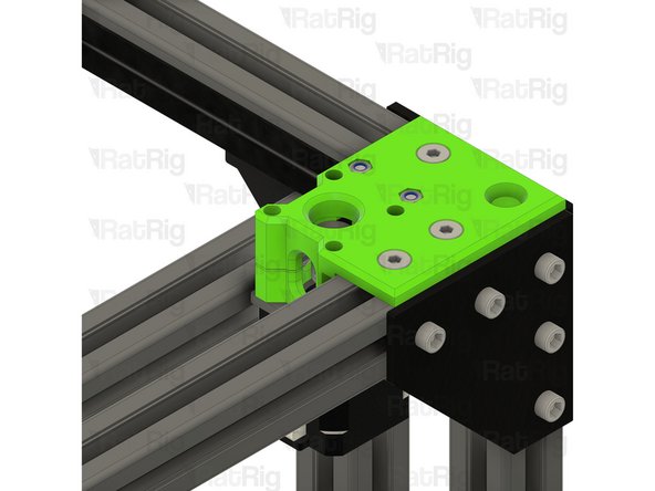
Insert two M5x40 Cap Head Screws into the motor_plate, as shown, in preparation for Step 14
-
-
-
3x M6x14 Countersink Screw
-
3x 3030 Drop-in T-Nut - M6
-
1x xy_motor_cage_bottom_right_3.1 Printed Part
-
1x xy_motor_cage_top_right_3.1 Printed Part
-
6x F695ZZ Ball Bearing
-
3x 695ZZ Ball Bearing
-
5x Mini Precision Shim
-
2x M5 Nylon Locking Hex Nut
-
-
-
V-Core 3.1 Frame Assembly - Rear Right Corner
-
Install the following components in the order shown in the image:
-
Mini Precision Shim
-
F695ZZ Ball Bearing (Flange at the bottom)
-
695ZZ Ball Bearing
-
F695ZZ Ball Bearing (Flange at the top)
-
-
-
xy_motor_cage_bottom_right_3.1 Printed Part
-
Place the xy_motor_cage_bottom_right_3.1 printed part as shown
-
The xy_motor_cage_bottom_right part will just sit on the plate for now, it will be secured in Step 20
-
-
-
Loose end of the bottom CoreXY belt
-
Form a loop as shown, this will be used to engage with the NEMA17 motor pulley
-
Position the bottom belt as shown
-
Loose end of the top CoreXY belt
-
Slot this end of the top CoreXY belt around the top bearing stack as shown
-
Make sure that both belts match the third image before proceeding
-
-
-
3030 Drop-in T-Nut - M6
-
xy_motor_cage_top_right_3.1 Printed Part
-
M6x14 Countersink Screw
-
Loosely thread a 3030 T-Nut onto each of the M6x14 screws. Do not tighten them at this point.
-
M5 Nylon Locking Hex Nut
-
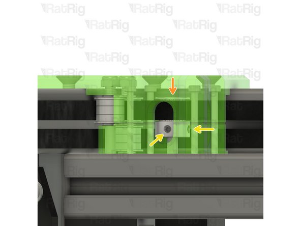
Install the xy_motor_cage_right_top assembly onto the frame as shown
-
Tighten the three marked M6x14 screws to secure the CoreXY motor cage top to the frame
-
Tighten the M5x40 screws, on the underside, to secure the bearing stacks into the CoreXY motor cage top
-
-
-
1x 20 Tooth 2GT Timing Pulley for 9mm Belt
-
1x 48mm NEMA17 Stepper Motor
-
4x M3x35 Cap Head Screw
-
-
-
20 Tooth 2GT Timing Pulley for 9mm Belt
-
Install the timing pulley onto the NEMA17 shaft, oriented as shown
-
Align one of the M3 grub screws on the timing pulley so that it will tighten against the flat on the NEMA17 shaft
-
Position the timing pulley so the marked gap is 3mm
-
Slightly tighten one of the M3 grub screws to hold the timing pulley in position for now
-
The timing pulley will be aligned and fully secured in the next step
-
Position the NEMA17 motor up and into the motor cage from below, it will be secured in the next step
-
-
-
Insert the M3x35 screws into the xy_motor_cage_right_top as shown, and fasten them to secure the NEMA17 motor to the mount
-
Check the alignment of the timing pulley, the belt should be on the middle of the pulley as shown
-
Adjust the pulley up or down if required to make sure the belt is in the middle of the pulley
-
Fasten both M3 grub screws to securely mount the timing pulley to the NEMA17 motor shaft
-


Cancel: I did not complete this guide.
33 other people completed this guide.