
Steps
19
- 06. X-Axis Assembly 19 steps

User-Contributed Guide
This guide is not managed by the site's staff.
Quiz
0
Introduction
Please note: All measurements and component counts provided in this guide are based upon building a 300x300 V-Core 3.
If you are building a machine of a different size, please refer to the following list for the linear rail length, 2020 extrusion length, and required number of fasteners:
- 200x200: 300mm Linear Rail, 322mm 2020 Extrusion, 6x M3x8 Screw & 2020 T-Nuts
- 300x300: 400mm Linear Rail, 422mm 2020 Extrusion, 8x M3x8 Screw & 2020 T-Nuts
- 400x400: 500mm Linear Rail, 522mm 2020 Extrusion, 10x M3x8 Screw & 2020 T-Nuts
- 500x500: 600mm Linear Rail, 622mm 2020 Extrusion, 12x M3x8 Screw & 2020 T-Nuts
-
-
1x xy_joiner_left_3.1 Printed Part
-
1x xy_joiner_right_3.1 Printed Part
-
4x 695ZZ Ball Bearing
-
8x F695ZZ Ball Bearing
-
12x Mini Precision Shim
-
8x 6mm Aluminium Spacer
-
4x M5x55 Cap Head Screw
-
-
-
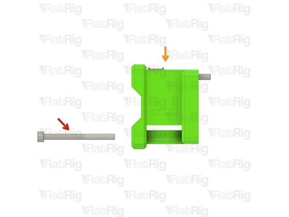
M5x55 Cap Head Screw
-
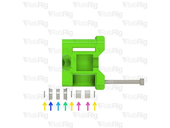
xy_joiner_left_3.1 Printed Part
-
Install the following components in the order shown in the image:
-
Mini Precision Shim
-
F695ZZ Ball Bearing (Flange at the top)
-
695ZZ Ball Bearing
-
F695ZZ Ball Bearing (Flange at the bottom)
-
6mm Aluminium Spacer
-
-
-
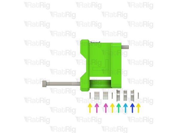
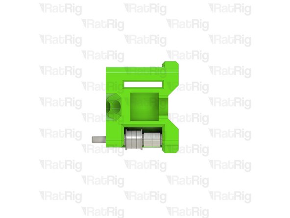
M5x55 Cap Head Screw
-
Assembly from the previous step
-
Install the following components in the order shown in the image:
-
Mini Precision Shim
-
F695ZZ Ball Bearing (Flange at the top)
-
695ZZ Ball Bearing
-
F695ZZ Ball Bearing (Flange at the bottom)
-
6mm Aluminium Spacer
-
-
-
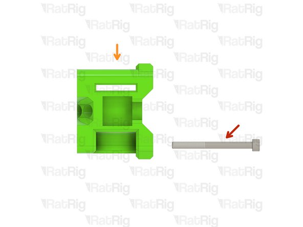
M5x55 Cap Head Screw
-
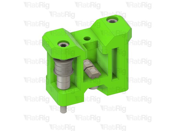
xy_joiner_right_3.1 Printed Part
-
Install the following components in the order shown in the image:
-
Mini Precision Shim
-
F695ZZ Ball Bearing (Flange at the top)
-
695ZZ Ball Bearing
-
F695ZZ Ball Bearing (Flange at the bottom)
-
6mm Aluminium Spacer
-
-
-
M5x55 Cap Head Screw
-
Assembly from the previous step
-
Install the following components in the order shown in the image:
-
Mini Precision Shim
-
F695ZZ Ball Bearing (Flange at the top)
-
695ZZ Ball Bearing
-
F695ZZ Ball Bearing (Flange at the bottom)
-
6mm Aluminium Spacer
-
-
-
1x 422mm 2020 Extrusion
-
1x 400mm MGN12 Linear Rail
-
8x M3x8 Cap Head Screw & 2020 Drop-in T-Nut - M3
-
4x M5x10 Cap Head Screw
-
6x 2020 Square T-Nut - M5
-
1x M5x18 Cap Head Screw
-
1x M5x12 Cap Head Screw
-
1x x_endstop_block_3.1 Printed Part
-
-
-
Assembly from Step 3
-
M5x10 Cap Head Screw
-
2020 Square T-Nut - M5
-
Loosely thread a 2020 Square T-Nut onto each of the M5x10 screws
-
Assembly from Step 5
-
-
-
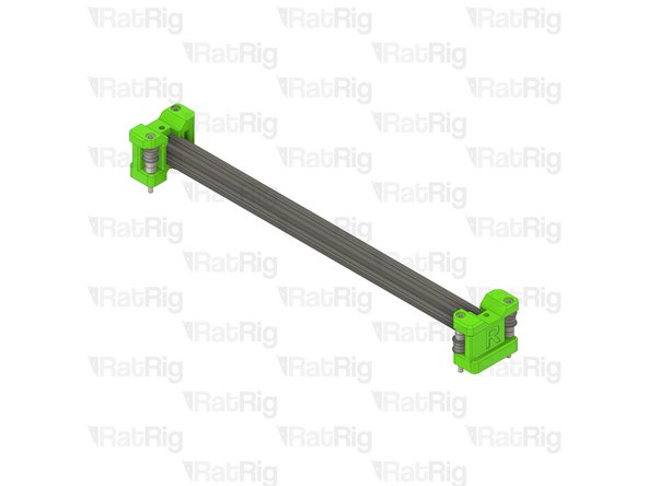
422mm 2020 Extrusion
-
2020 Square T-Nut - M5
-
Install one 2020 Square T-Nut into the top slot on each end of the 2020 extrusion
-
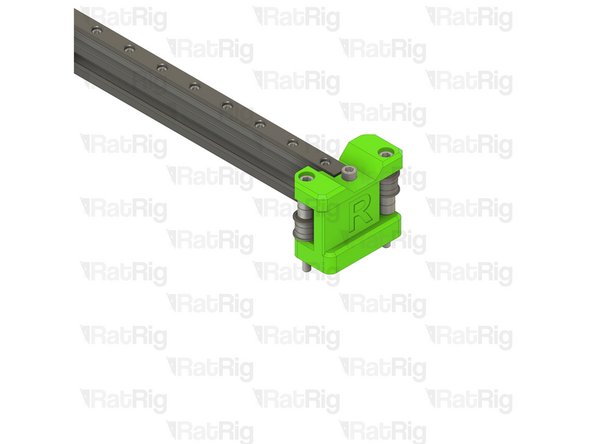
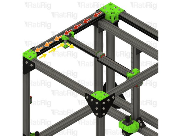
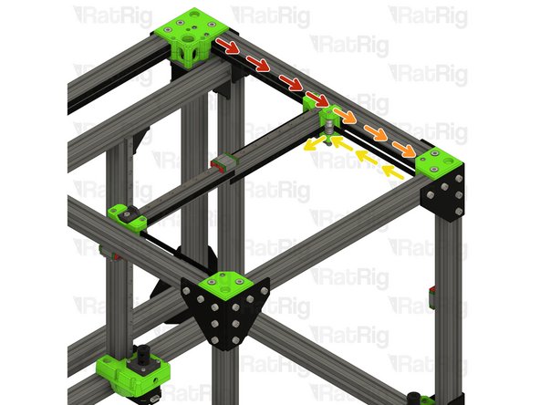
Install the left x-axis end onto one end of the 2020 Extrusion
-
Install the right x-axis end onto the other end of the 2020 Extrusion
-
Make sure the x-axis ends are fully installed on the 2020 extrusion before proceeding
-
-
-
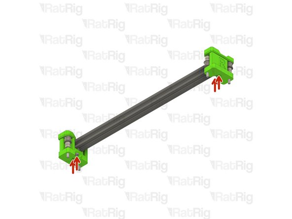
Tighten the marked M5x10 screws to secure the x-axis ends to the 2020 extrusion
-
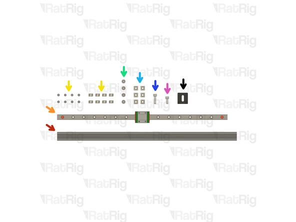
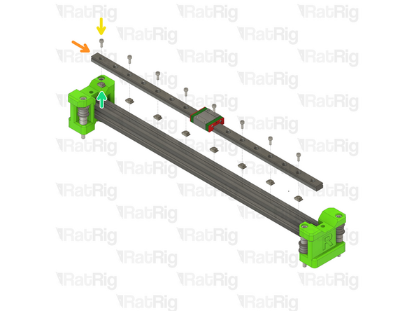
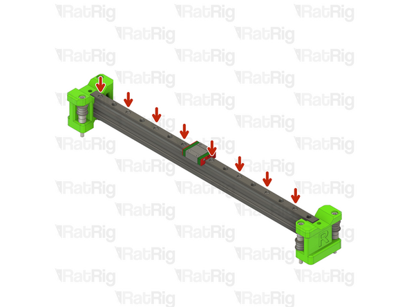
400mm MGN12 Linear Rail
-
Insert an M3x8 screw into every other hole in the linear rail
-
Loosely thread a 2020 T-Nut onto each of the M3x8 screws
-
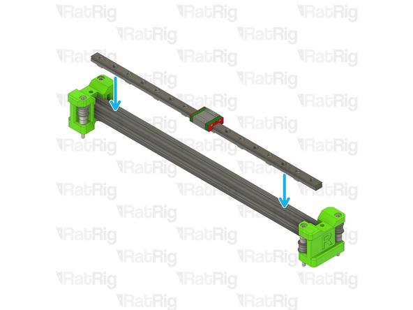
Install the linear rail into the 2020 extrusion as shown
-
-
-
Fasten the marked M3x8 screws, starting from the left
-
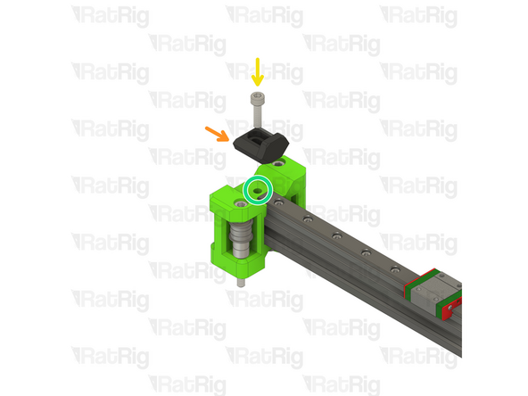
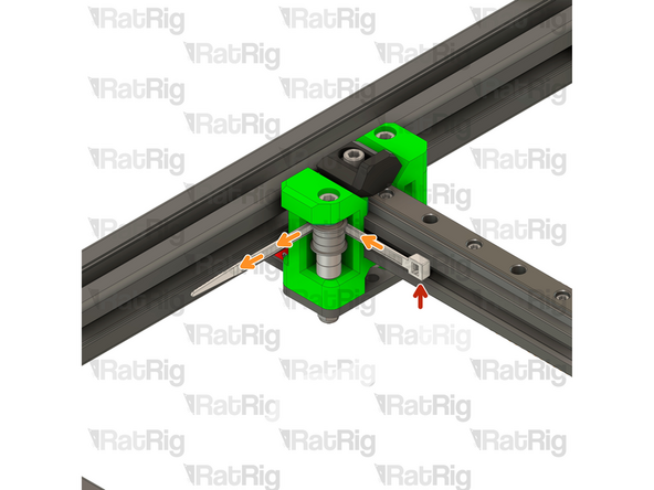
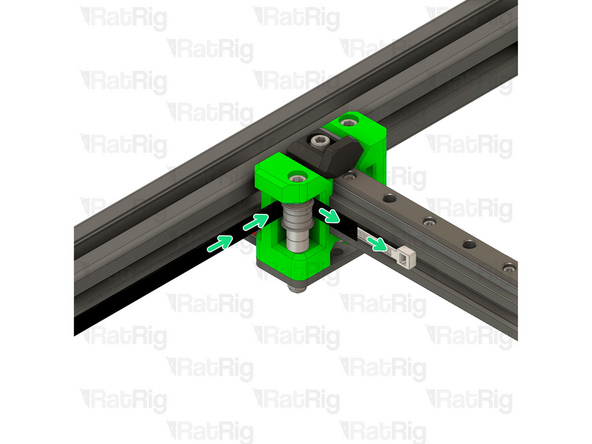
x_endstop_block_3.1 Printed Part
-
M5x18 Cap Head Screw
-
Make sure the previously installed 2020 square T-Nut is aligned with the marked hole. A small screwdriver or hex key can be used to help position it correctly
-
The correct positioning for the x_endstop_block will be set when building the EVA3 assembly at a later point
-
Take care not to over tighten the M5x18 screw as you can damage the printed parts
-
-
-
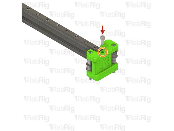
M5x12 Cap Head Screw
-
Make sure the previously installed 2020 square T-Nut is aligned with the marked hole. A small screwdriver or hex key can be used to help position it correctly
-
Take care not to over tighten the M5x12 screw as you can damage the printed parts
-
-
-
2x xy_joiner_plate
-
4x M5 Nylon Locking Hex Nut
-
8x M3x8 Cap Head Screw
-
-
-
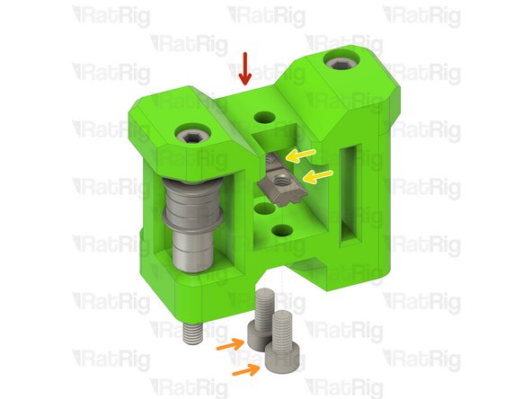
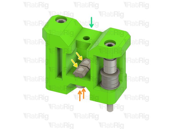
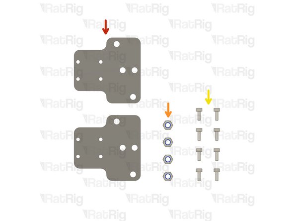
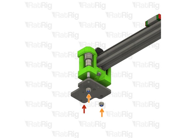
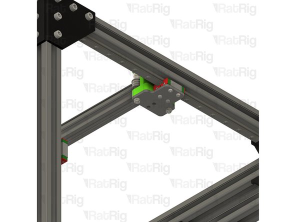
xy_joiner_plate
-
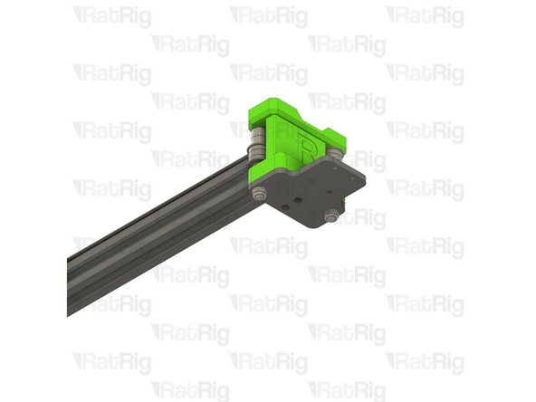
Check that the xy_joiner_plate is installed in the correct orientation. It should be flush with the xy_joiner printed part. If it is not, flip the plate upside down and check again
-
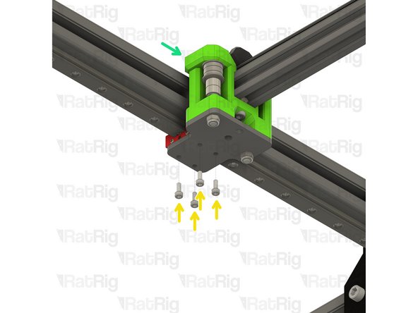
M5 Nylon Locking Hex Nut
-
Tighten the M5x55 screws into the M5 nylon locking hex nuts to secure the plate to the printed part
-
Repeat these steps for the right hand side
-
-
-
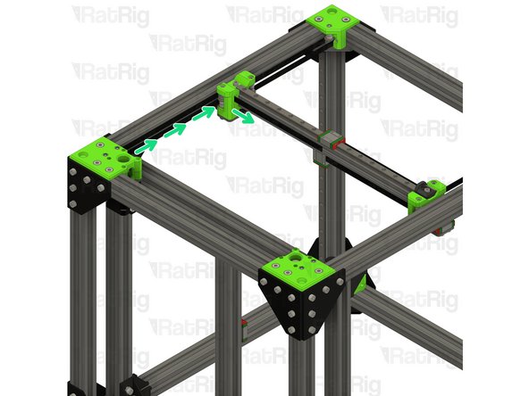
V-Core 3.1 Frame Assembly
-
X-axis Assembly (Right side)
-
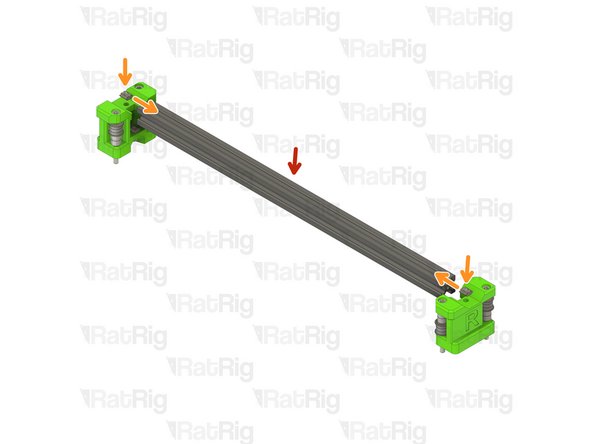
M3x8 Cap Head Screw
-
Secure the right side of the x-axis to the right y-axis linear rail as shown
-
X-axis Assembly (Left side)
-
Secure the left side of the x-axis to the left y-axis linear rail as shown
-
-
-
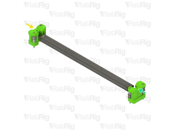
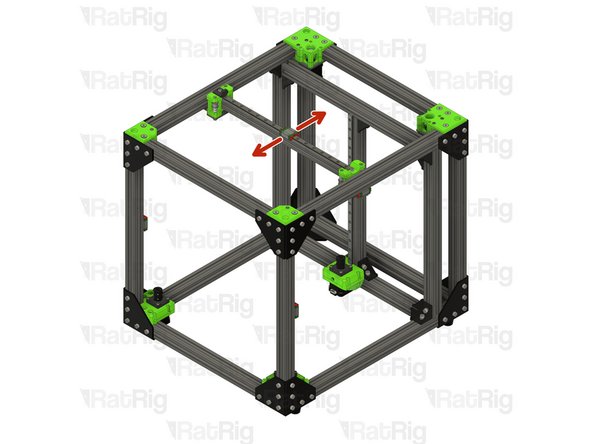
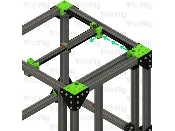
Test the movement of the y-axis over the full travel distance
-
Small changes in resistance are normal, but becoming much harder to push, or binding completely are not
-
-
-
This step is not mandatory, it's just a Rat Rig tip on how to feed the belts on the idlers.
-
Zip Tie
-
The wider the zip tie is, the easier the process will be
-
Bend the tip of the zip tie a little bit and feed it between the printed part and the idler, as shown
-
Insert the belt between the zip tie and the idler
-
Slowly feed the belt and pull the zip tie at the same time
-
-
-
Take the loose end of the top CoreXY belt on the left hand side:
-
Feed the belt behind the left xy_joiner
-
Down and around the front xy_idler
-
Around the front bearing stack on the left xy_joiner
-
Take the loose end of the bottom CoreXY belt on the left hand side:
-
Feed the belt around the rear bearing stack on the xy_joiner
-
-
-
Take the loose end of the bottom CoreXY belt on the right hand side:
-
Feed the belt behind the right xy_joiner
-
Down and around the front xy_idler
-
Around the front bearing stack on the right xy_joiner
-
Take the loose end of the top CoreXY belt on the right hand side:
-
Feed the belt around the rear bearing stack on the xy_joiner
-


Cancel: I did not complete this guide.
29 other people completed this guide.
One Comment
The correct positioning for the x_endstop_block will be set when building the EVA3 assembly at a later point
The rest of the guide never goes into detail of how to set the x and y endstops position correctly? The EVA section doesn't have it nor the last section after it. which it goes over tensioning of the belt.