
Steps
19
- 06. X-Axis Assembly 19 steps

User-Contributed Guide
This guide is not managed by the site's staff.
Quiz
0
Introduction
Please note: All measurements and component counts provided in this guide are based upon building a 300x300 V-Core 3.
If you are building a machine of a different size, please refer to the following list for the linear rail length, 2020 extrusion length, and required number of fasteners:
- 200x200: 300mm Linear Rail, 322mm 2020 Extrusion, 6x M3x8 Screw & 2020 T-Nuts
- 300x300: 400mm Linear Rail, 422mm 2020 Extrusion, 8x M3x8 Screw & 2020 T-Nuts
- 400x400: 500mm Linear Rail, 522mm 2020 Extrusion, 10x M3x8 Screw & 2020 T-Nuts
- 500x500: 600mm Linear Rail, 622mm 2020 Extrusion, 12x M3x8 Screw & 2020 T-Nuts
-
-
1x xy_joiner_left_3.1 Printed Part
-
1x xy_joiner_right_3.1 Printed Part
-
4x 695ZZ Ball Bearing
-
8x F695ZZ Ball Bearing
-
12x Mini Precision Shim
-
8x 6mm Aluminium Spacer
-
4x M5x55 Cap Head Screw
-
-
-
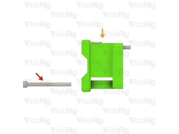
M5x55 Cap Head Screw
-
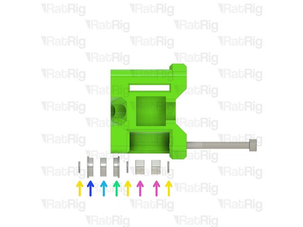
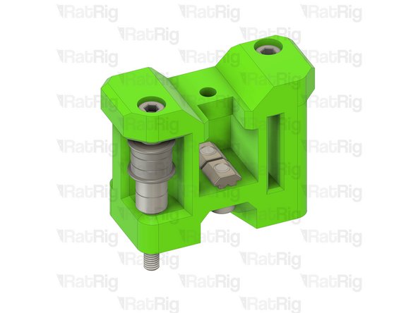
xy_joiner_left_3.1 Printed Part
-
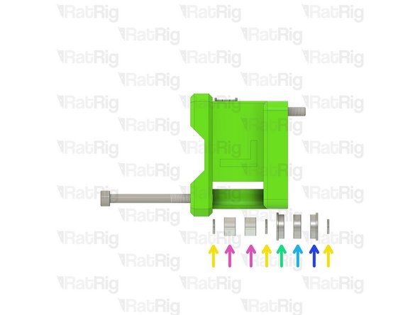
Install the following components in the order shown in the image:
-
Mini Precision Shim
-
F695ZZ Ball Bearing (Flange at the top)
-
695ZZ Ball Bearing
-
F695ZZ Ball Bearing (Flange at the bottom)
-
6mm Aluminium Spacer
-
-
-
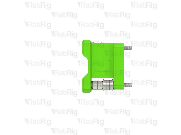
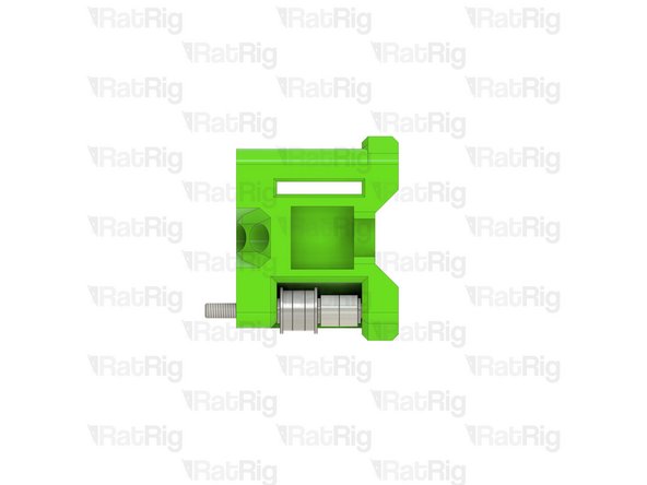
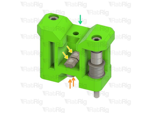
M5x55 Cap Head Screw
-
Assembly from the previous step
-
Install the following components in the order shown in the image:
-
Mini Precision Shim
-
F695ZZ Ball Bearing (Flange at the top)
-
695ZZ Ball Bearing
-
F695ZZ Ball Bearing (Flange at the bottom)
-
6mm Aluminium Spacer
-
-
-
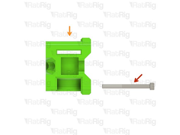
M5x55 Cap Head Screw
-
xy_joiner_right_3.1 Printed Part
-
Install the following components in the order shown in the image:
-
Mini Precision Shim
-
F695ZZ Ball Bearing (Flange at the top)
-
695ZZ Ball Bearing
-
F695ZZ Ball Bearing (Flange at the bottom)
-
6mm Aluminium Spacer
-
-
-
M5x55 Cap Head Screw
-
Assembly from the previous step
-
Install the following components in the order shown in the image:
-
Mini Precision Shim
-
F695ZZ Ball Bearing (Flange at the top)
-
695ZZ Ball Bearing
-
F695ZZ Ball Bearing (Flange at the bottom)
-
6mm Aluminium Spacer
-
-
-
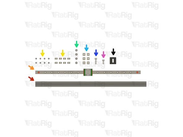
1x 422mm 2020 Extrusion
-
1x 400mm MGN12 Linear Rail
-
8x M3x8 Cap Head Screw & 2020 Drop-in T-Nut - M3
-
4x M5x10 Cap Head Screw
-
6x 2020 Square T-Nut - M5
-
1x M5x18 Cap Head Screw
-
1x M5x12 Cap Head Screw
-
1x x_endstop_block_3.1 Printed Part
200x200: 300mm Linear Rail, 322mm 2020 Extrusion, 12x M3x8 Screw & 2020 T-Nuts
300x300: 400mm Linear Rail, 422mm 2020 Extrusion, 16x M3x8 Screw & 2020 T-Nuts
400x400: 500mm Linear Rail, 522mm 2020 Extrusion, 20x M3x8 Screw & 2020 T-Nuts
500x500: 600mm Linear Rail, 622mm 2020 Extrusion, 24x M3x8 Screw & 2020 T-Nuts
-
-
-
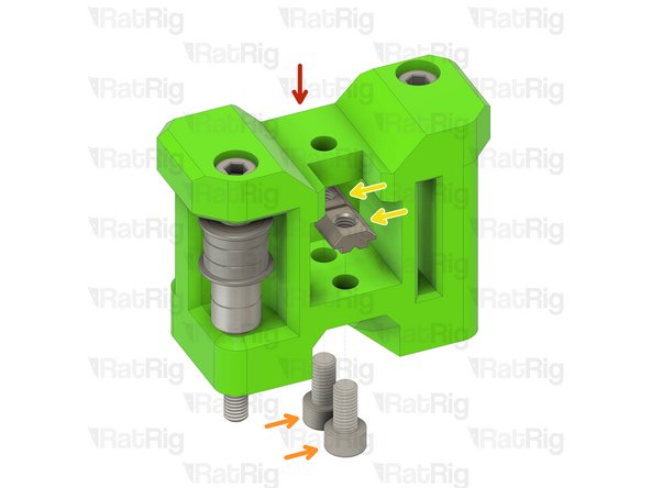
Assembly from Step 3
-
M5x10 Cap Head Screw
-
2020 Square T-Nut - M5
-
Loosely thread a 2020 Square T-Nut onto each of the M5x10 screws
-
Assembly from Step 5
Easier to just slide the T-nuts in the gantry then slide them into position
Absolute Prodigy - Resolved on Release Reply
-
-
-
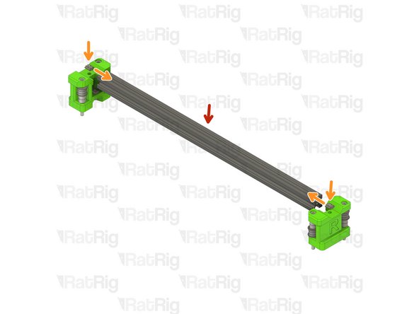
422mm 2020 Extrusion
-
2020 Square T-Nut - M5
-
Install one 2020 Square T-Nut into the top slot on each end of the 2020 extrusion
-
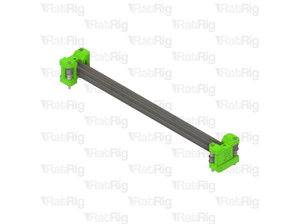
Install the left x-axis end onto one end of the 2020 Extrusion
-
Install the right x-axis end onto the other end of the 2020 Extrusion
-
Make sure the x-axis ends are fully installed on the 2020 extrusion before proceeding
Screw in a M5 Cap head screw into each free M5 square nut avoid their sliding beetwen the printed part and the extrusion.
Mihály Farkas - Resolved on Release Reply
i gave up trying to do it per instructions.
instead i took of t-nuts, slid them on to the extrusion, and placed 3d printed assembly on the extrusion, and slid t-nuts back in... much simpler
out of marbles - Resolved on Release Reply
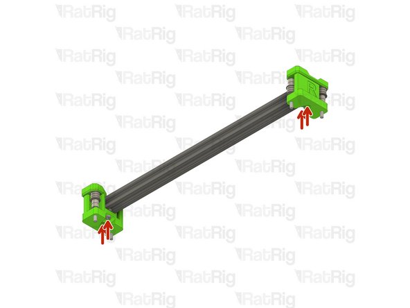
-
-
-
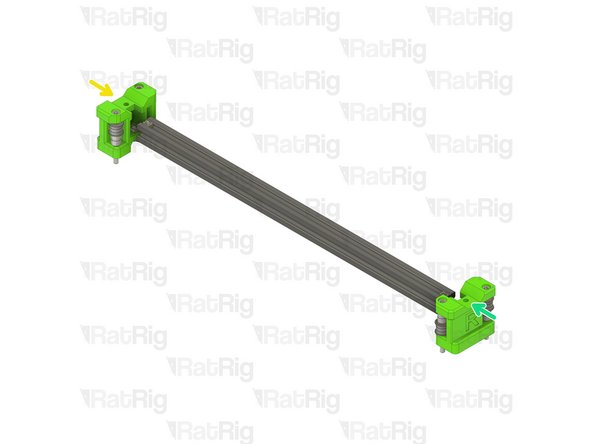
Tighten the marked M5x10 screws to secure the x-axis ends to the 2020 extrusion
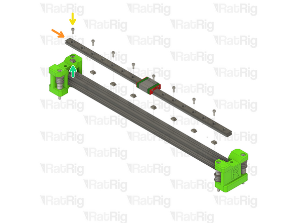
-
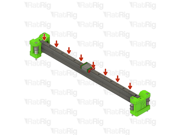
400mm MGN12 Linear Rail
-
Insert an M3x8 screw into every other hole in the linear rail
-
Loosely thread a 2020 T-Nut onto each of the M3x8 screws
-
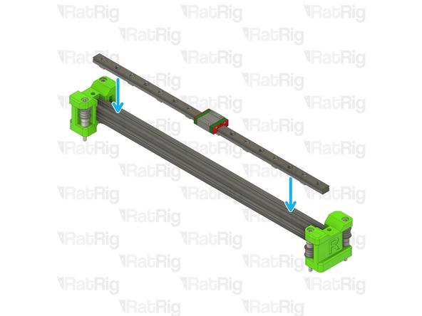
Install the linear rail into the 2020 extrusion as shown
-
-
-
Fasten the marked M3x8 screws, starting from the left
-
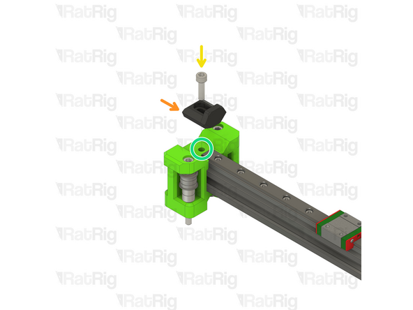
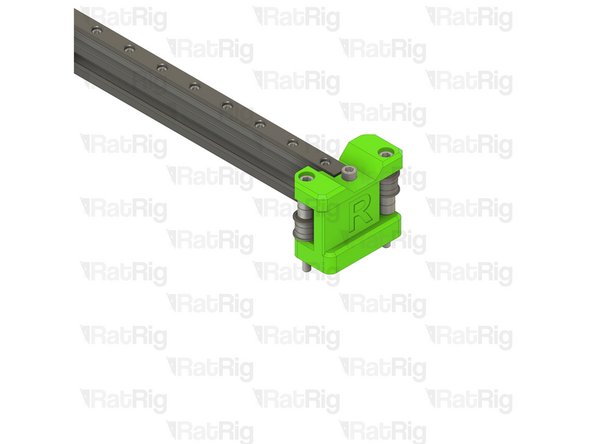
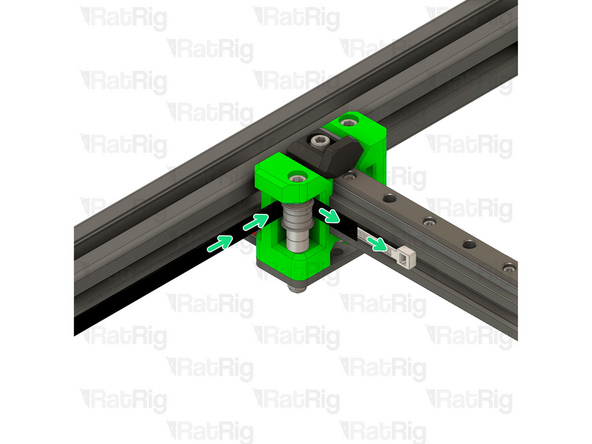
x_endstop_block_3.1 Printed Part
-
M5x18 Cap Head Screw
-
Make sure the previously installed 2020 square T-Nut is aligned with the marked hole. A small screwdriver or hex key can be used to help position it correctly
-
The correct positioning for the x_endstop_block will be set when building the EVA3 assembly at a later point
-
Take care not to over tighten the M5x18 screw as you can damage the printed parts
-
-
-
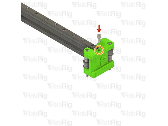
M5x12 Cap Head Screw
-
Make sure the previously installed 2020 square T-Nut is aligned with the marked hole. A small screwdriver or hex key can be used to help position it correctly
-
Take care not to over tighten the M5x12 screw as you can damage the printed parts
-
-
-
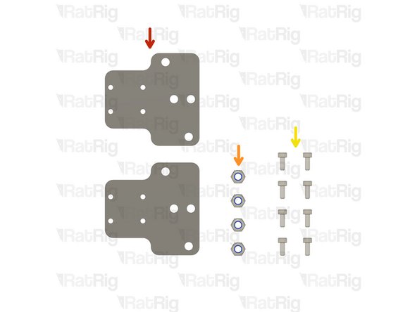
2x xy_joiner_plate
-
4x M5 Nylon Locking Hex Nut
-
8x M3x8 Cap Head Screw
-
-
-
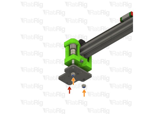
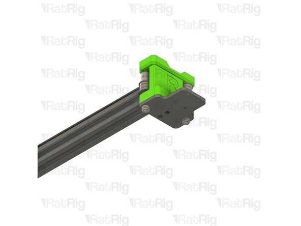
xy_joiner_plate
-
Check that the xy_joiner_plate is installed in the correct orientation. It should be flush with the xy_joiner printed part. If it is not, flip the plate upside down and check again
-
M5 Nylon Locking Hex Nut
-
Tighten the M5x55 screws into the M5 nylon locking hex nuts to secure the plate to the printed part
-
Repeat these steps for the right hand side
-
-
-
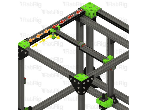
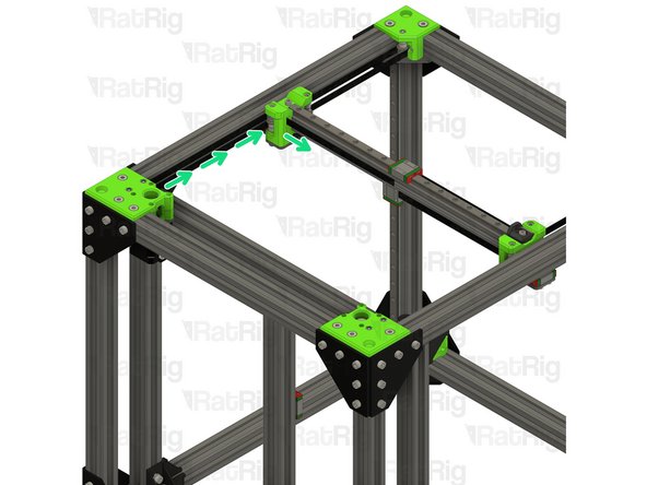
V-Core 3.1 Frame Assembly
-
X-axis Assembly (Right side)
-
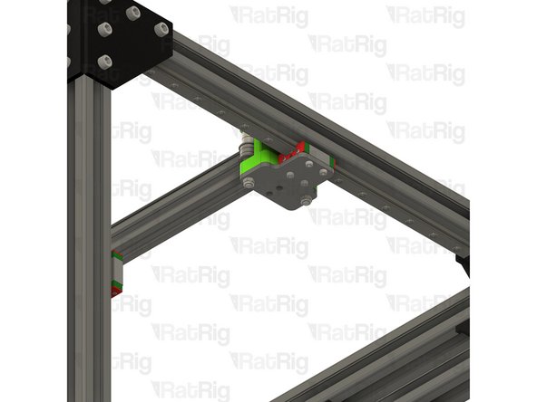
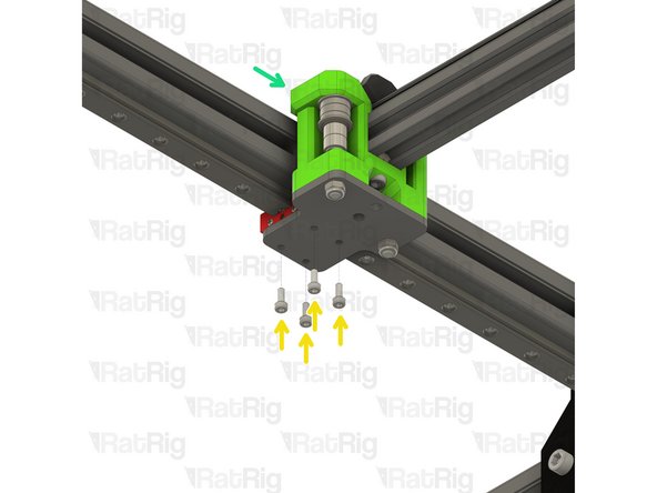
M3x8 Cap Head Screw
-
Secure the right side of the x-axis to the right y-axis linear rail as shown
-
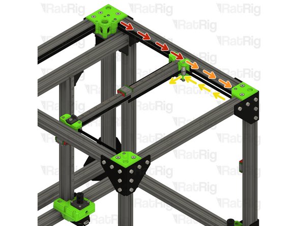
X-axis Assembly (Left side)
-
Secure the left side of the x-axis to the left y-axis linear rail as shown
I found that it was actually infinitely easier to route the belts through the gantry at this step, rather than later. Especially through the rear pulleys, those become near impossible to route once the gantry is installed. The belts should have enough slack to reach the pulleys even when the gantry is resting on the bottom of the machine.
Fabian Leijström - Resolved on Release Reply
-
-
-
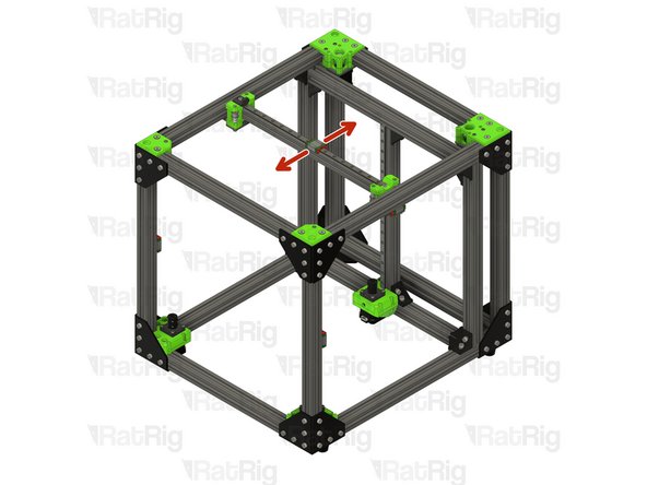
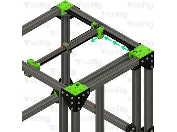
Test the movement of the y-axis over the full travel distance
-
Small changes in resistance are normal, but becoming much harder to push, or binding completely are not
I tried the above methods from Jakob V. and David W. (thank you both for posting). For me those things didn’t work. I noticed that the 2020 extrusion was a hair too long. I was able to determine this by mounting one side of the assembly to the rail and looked at the holes between the Joiner plate and the rail block on the opposite side and saw they were off by about 1-2mm. I trimmed the bar by this amount and re-assembled. Works amazing now. It truly is silky smooth now when all is setup right.
Maxwell Hormilla - Resolved on Release Reply
I noticed some slight binding and the x axis seemed to not be square to the top. I loosened the two bottom M5 x 10 bolts on each side and the top M5 bolts. This allowed the length to assume the correct size and then I squared it to the front extrusion. I used some tape to hold it against the front and tightened the M5 bolts This made it much smoother and corrected the skew to the frame. It is now very smooth and square.
david wilson - Resolved on Release Reply
Thanks for the tip. My printed parts were super tight around the 2020 extrusion so loosening those M5 bolts and then forcefully making them skew back and forth and then pushing and pulling in the Z axis slowly worked it to a point where it was loose enough to slide freely.
Troy -
I took my gantry off again during this process as I noticed the right x-axis gantry fastener was not sitting flat on the right XY Joiner Plate. To correct this I put the gantry, with both gantry fasteners attached, on a flat table and put sandpaper under the right side gantry fastener. I then moved the right side gantry fastener back and forth on the sandpaper to flatten the bottom which made it sit flat on the table.
After having reattached it to the two Joiner Plates, I still had to work a bit with how tight I bolted the gantry down, which ended up not being very much, to avoid the carriages gripping the rail so much that the movement became uneven as I tested moving the gantry on the Y-axis.
Jakob Ventzel - Resolved on Release Reply
-
-
-
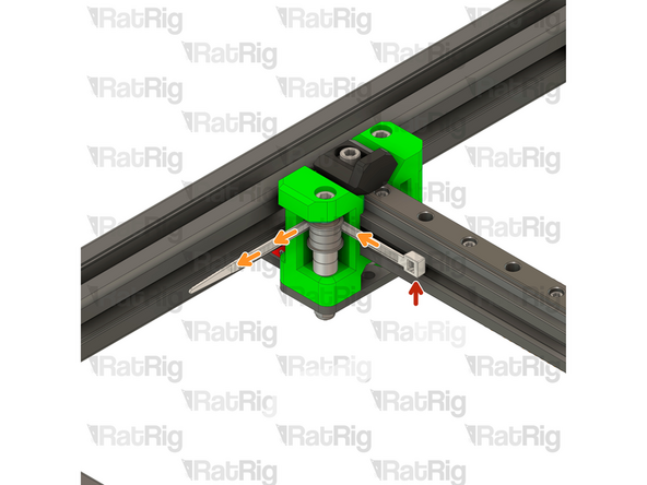
This step is not mandatory, it's just a Rat Rig tip on how to feed the belts on the idlers.
-
Zip Tie
-
The wider the zip tie is, the easier the process will be
-
Bend the tip of the zip tie a little bit and feed it between the printed part and the idler, as shown
-
Insert the belt between the zip tie and the idler
-
Slowly feed the belt and pull the zip tie at the same time
-
-
-
Take the loose end of the top CoreXY belt on the left hand side:
-
Feed the belt behind the left xy_joiner
-
Down and around the front xy_idler
-
Around the front bearing stack on the left xy_joiner
-
Take the loose end of the bottom CoreXY belt on the left hand side:
-
Feed the belt around the rear bearing stack on the xy_joiner
Fiddled with this for some time thinking it was not possible….
But you can feed the other end of the belt back through the wrong way though, so do this with it tooth to tooth with the correct belt, then engage about an inch of belt tooth to tooth and its stiff but you can pull the belt through to where its suposed to go.
Andy Collins - Resolved on Release Reply
The zip tie trick worked well for all but the very last step. For that one, I had to use Josh Ward's trick, meshing the teeth of two pieces of belt together and holding them thus with a small piece of very thin adhesive tape, then pulling them both thru the rear bearing stack on the xy_joiner.
John Vybiral - Resolved on Release Reply
The new system seems much tighter than the old metal ones. I could not get the front idlers to thread even with a zip tie, I removed the M6 x 10 bolt that fastens from the back and was able to get just enough give to thread the belt using the zip tie. I had used an old piece of belt with the original 3.0, but that is no longer an option. It seems every thing is just a little too tight. I like the new roller system, but a little more gap could have been built in.
david wilson - Resolved on Release Reply
+1 for the zip tie trick. Worked perfectly from the very first try.
Kenneth Jensen - Resolved on Release Reply
I used a small piece of tape to initiate the roll and the push the belt and it went around. Took me about 5 seconds belt/corner. Works very good on these new idlers.
Roberto Hernandez - Resolved on Release Reply
Use a small zip tie inserted from the other direction to easily make the turn. Interest the belt between the bearings stack and the zip tie, keep pushing the belt as you gently pull the zip tie and done. Then just move the belt back and forth to move it up or down into the gap between flanges.
Lance Taylor-Warren - Resolved on Release Reply
This is most impossible instruction, good luck everyone who got to this step.
vitalii.topoliuk@gmail.com - Resolved on Release Reply
To route around the front idlers, it may be helpful to insert the other end of the belt through from the exit, with teeth facing out, then meshing that belt and the one you want to feed, and pulling back out.
I did this but instead of using the teeth to mesh, I used tape to connect the two loose ends. Worked first try.
this trick is very useful if you have 10 cm or so of belt from your last printer or just another scrap.
-
-
-
Take the loose end of the bottom CoreXY belt on the right hand side:
-
Feed the belt behind the right xy_joiner
-
Down and around the front xy_idler
-
Around the front bearing stack on the right xy_joiner
-
Take the loose end of the top CoreXY belt on the right hand side:
-
Feed the belt around the rear bearing stack on the xy_joiner
I found that I had to keep the belts under a small amount of tension or the belt would slip out of place so I used paper clips to hold them in place without damaging the teeth.
Bruce Mackinlay - Resolved on Release Reply
-


Cancel: I did not complete this guide.
29 other people completed this guide.
One Comment
The correct positioning for the x_endstop_block will be set when building the EVA3 assembly at a later point
The rest of the guide never goes into detail of how to set the x and y endstops position correctly? The EVA section doesn't have it nor the last section after it. which it goes over tensioning of the belt.
I would avoid Step 1 trough 6 until you install the ends. Literally no reason why you cant do it the other way. If you follow this way, youll end up struggling with not having all the bearings fall out.
Roberto Hernandez - Resolved on Release Reply
Thanks for the tip. I followed your suggestion starting at step 6 to 11 and then 1 to 5 (with step 12 and 13 when finishing each x axis end) and then step 14 onward. Worked well without parts going everywhere
Troy -