Reputation over time
It looks like this user hasn't gained any reputation yet.
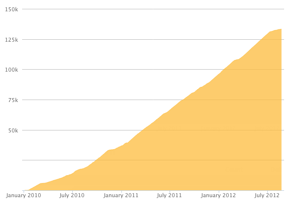
Once they have, you'll be able to view a graph of their reputation gained over time.
Here's a preview of what the graph will look like:
Reputation Breakdown
No reputation gained yet.
377
Print quality of the four holes is very bad. Had to spend a lot of time with various drills in the drill press, hemostats, channel locks, jeweler's hammer, etc,.
I could not get the nut to seat deep enough into it's cavity for the probe to go through, so I inserted the shank end of an 8mm. diameter drill into the probe bore and tapped on the printed part until the drill would slide thru freely. The nut was then fully seated. This all took WAY too much time.
Okay, I clamped the printed part so it wouldn't move around on me, with the “ fin” down, as per Josh' excellent idea. Next I used a tiny drop of super glue to attach one of the 6 flats on the nut to the long end of a hex wrench. Once the nut had been “stabbed” with a/much longer m3 screw and pulled into it's cavity, I twisted the wrench to break it free of the super glue.
This is a real challenge. A better design would eliminate the nut, and reduce the diameter of the hole that goes thru to the bore so that the m3 screw forms it's own tight threads into the printed part.
I found 2 pieces of tubing, same I.D., same O.D.. One is very straight, and very precisely cut to exactly 30.mm.. The other one has quite a pronounced curve, both ends are cut at a noticeable angle, and is roughly 77mm. long. Should I cut the long one down to 43.7mm. and use that?
The zip tie trick worked well for all but the very last step. For that one, I had to use Josh Ward's trick, meshing the teeth of two pieces of belt together and holding them thus with a small piece of very thin adhesive tape, then pulling them both thru the rear bearing stack on the xy_joiner.
To prevent the belts from slipping out of position, getting stepped on or otherwise pinched/damaged, consider wrapping the four loose belt ends temporarily around the 3030 extrusions and hold them in place with painter's tape. It's working well for me.
This step (3) is a lot easier with the entire frame assembly upside down.
The CAD assembly model available via OnShape shows a different orientation of the motor electrical connector from that shown in Step 8, below. Maybe either one is OK, as long as the connector is not facing a 3030 extrusion?
With the electronics panel firmly attached as shown in Step 15, I believe the thickness of that panel (in my case 1/8”, or 3.2mm.) should be subtracted from the 47mm. dimension, correct?
Page 1 of 2
Next