-
-
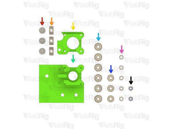
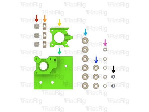
2x motor_plate
-
1x motor_support_left Printed Part
-
1x motor_support_right Printed Part
-
8x M6x12 Cap Head Screw
-
8x 3030 Drop-in T-Nut - M6
-
4x M5x40 Cap Head Screw
-
-
-
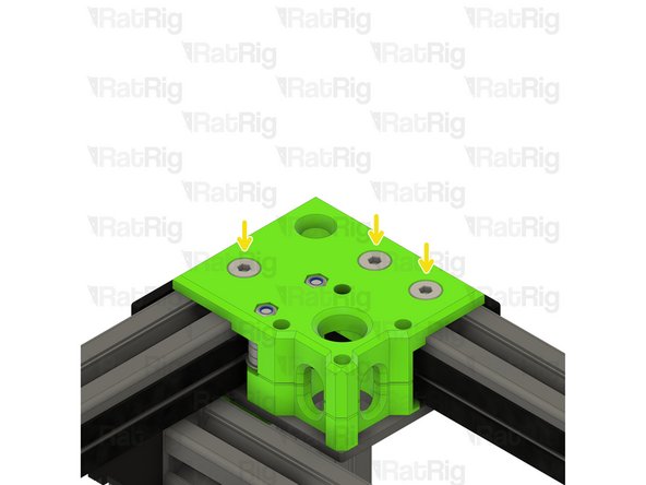
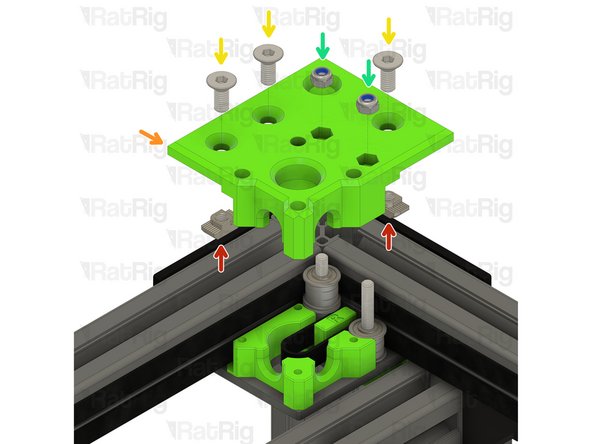
motor_plate
-
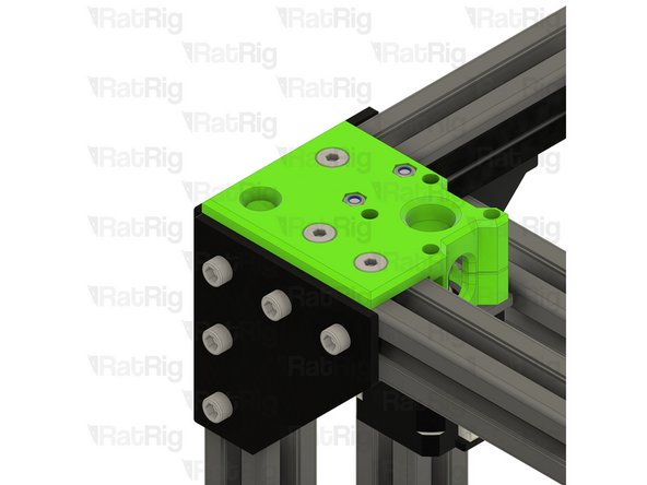
Make sure the motor plates are oriented as shown
-
motor_support_left Printed Part
-
M6x12 Cap Head Screw
-
3030 Drop-in T-Nut - M6
-
Loosely thread a 3030 T-Nut onto each of the M6x12 screws. Do not tighten them at this point.
-
motor_support_right Printed Part
-
Set the right motor plate assembly, and two M5x40 Cap Head Screws, aside until Step 12
-
-
-
V-Core 3.1 Frame Assembly - Rear Left Corner
-
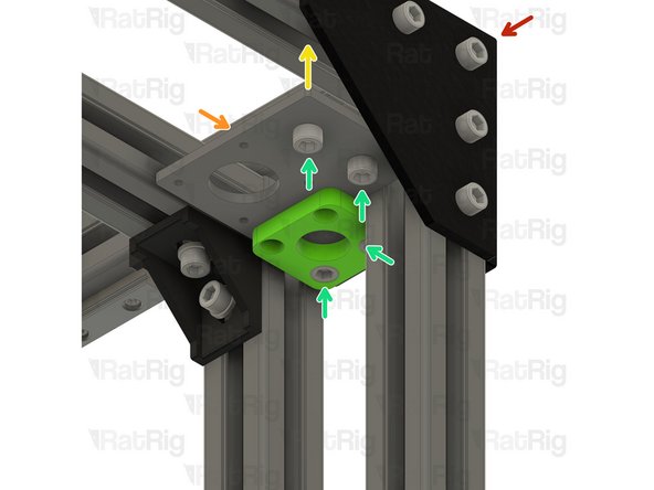
Left motor_plate assembly from Step 2
-
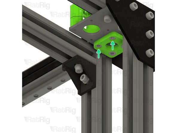
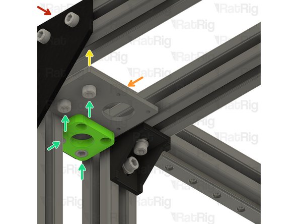
Install the left motor_plate assembly to the V-Core 3.1 frame as shown
-
Tighten the four M6x12 screws to secure the motor_plate assembly to the frame
-
Make sure the plate is fully seated against the 3030 extrusion before tightening the M6x12 screws
-
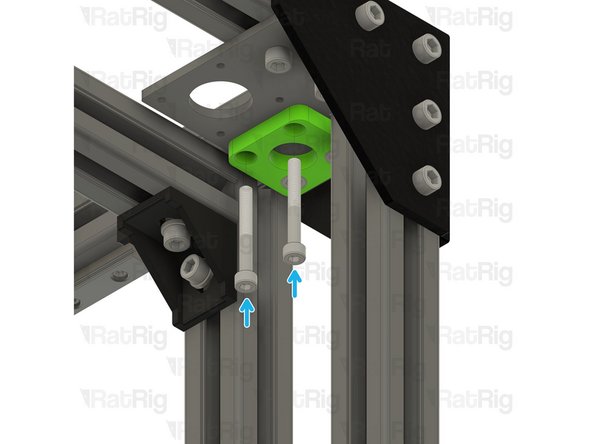
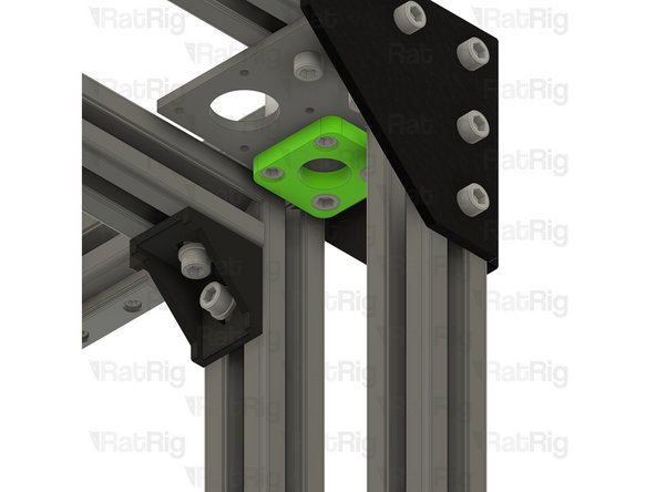
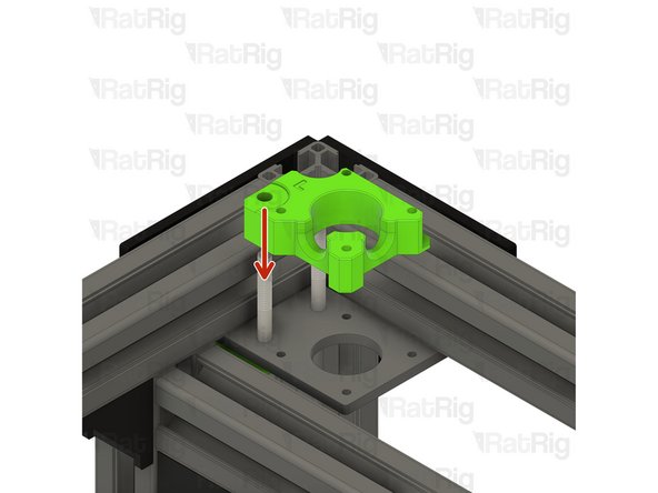
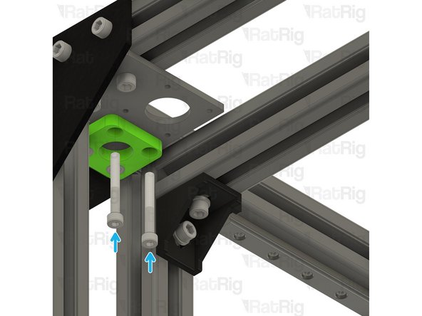
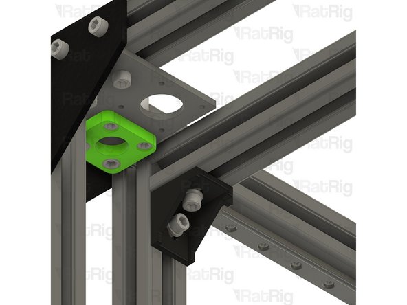
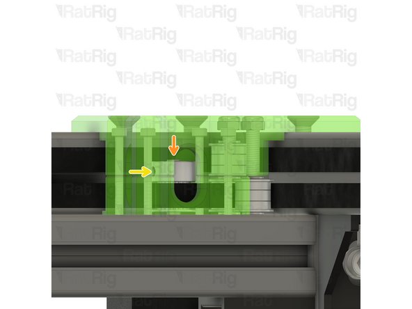
Insert two M5x40 screws into the motor_plate, as shown, in preparation for Step 5
-
-
-
3x M6x14 Countersink Screw
-
3x 3030 Drop-in T-Nut - M6
-
1x xy_motor_cage_bottom_left_3.1 Printed Part
-
1x xy_motor_cage_top_left_3.1 Printed Part
-
6x F695ZZ Ball Bearing
-
3x 695ZZ Ball Bearing
-
5x Mini Precision Shim
-
2x M5 Nylon Locking Hex Nut
-
-
-
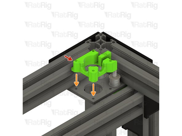
Install the xy_motor_cage_bottom_left printed part as shown
-
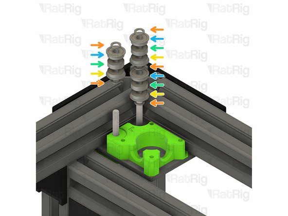
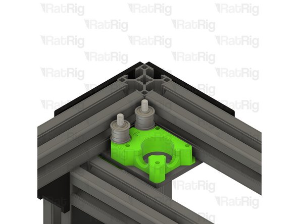
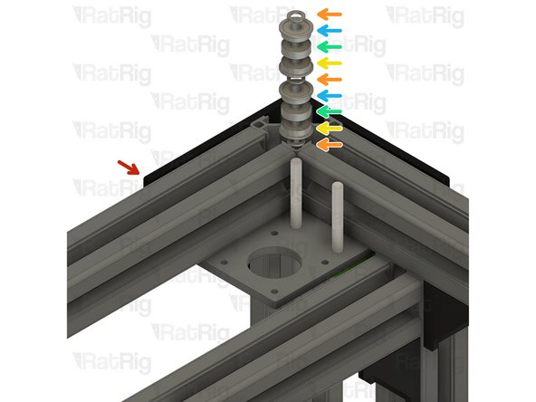
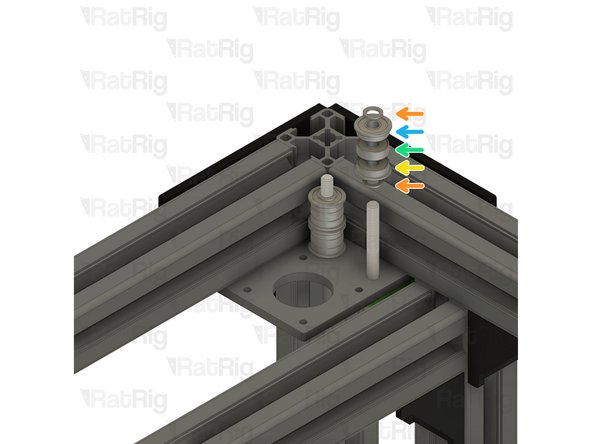
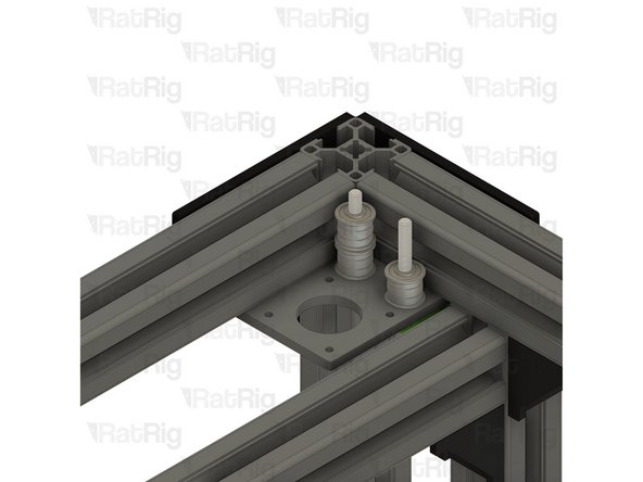
Install the following components in the order shown in the image:
-
Mini Precision Shim
-
F695ZZ Ball Bearing (Flange at the bottom)
-
695ZZ Ball Bearing
-
F695ZZ Ball Bearing (Flange at the top)
-
-
-
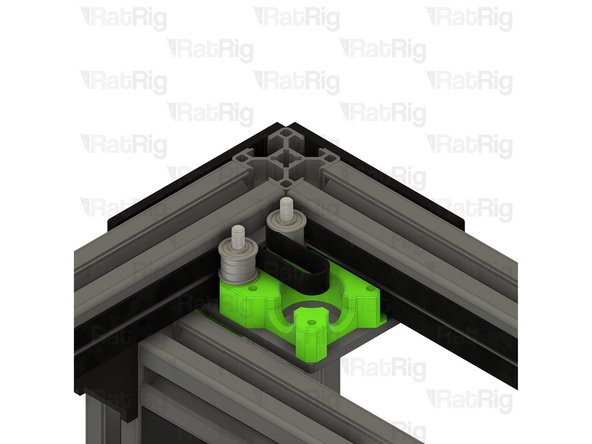
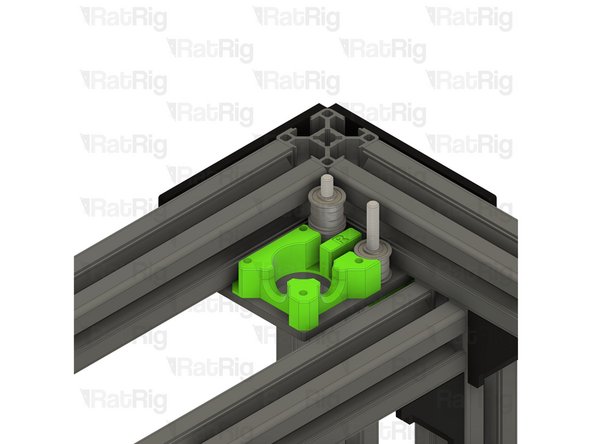
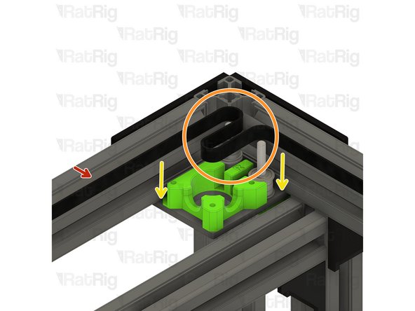
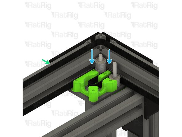
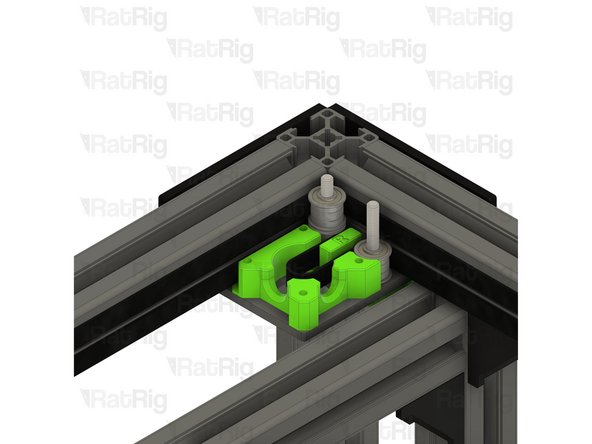
Proper installation of the belt is very important, failure to follow the instructions can lead to damage of the belt
-
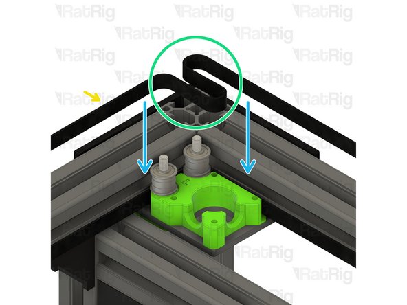
The CoreXY belt is provided in one continuous length. Unroll the belt and cut it in half to give you two belts of the same length
-
Position one half of the belt so that the toothed side faces the frame, and the smooth side faces the bearing stacks
-
Slot this half to the bottom of the CoreXY motor assembly, it should align with the bottom bearing stack
-
Take the other half of the CoreXY belt. Again, position the belt so that the toothed side faces the frame and the smooth side faces the bearing stacks
-
Form a loop as shown, this will be used to engage with the NEMA17 motor pulley
-
Position the upper belt as shown
-
Make sure that both belts match the third image before proceeding
-
-
-
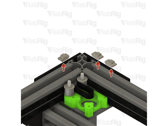
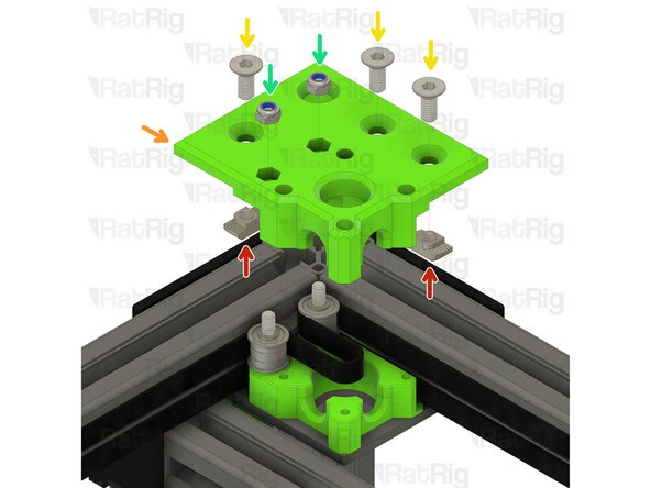
3030 Drop-in T-Nut - M6
-
xy_motor_cage_top_left_3.1 Printed Part
-
M6x14 Countersink Screw
-
Loosely thread a 3030 T-Nut onto each of the M6x14 screws. Do not tighten them at this point.
-
M5 Nylon Locking Hex Nut
-
-
-
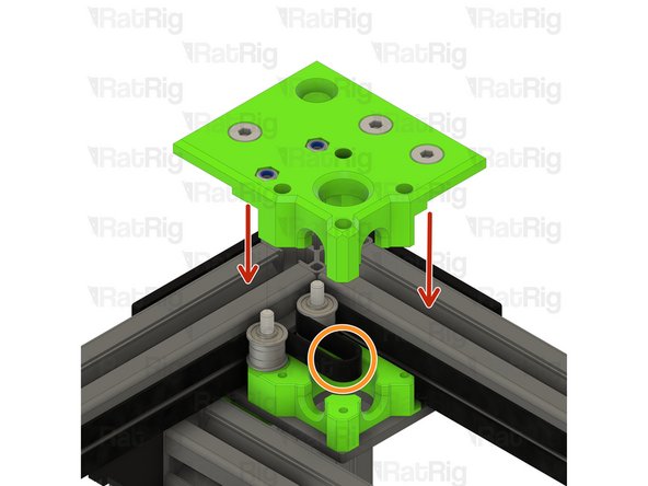
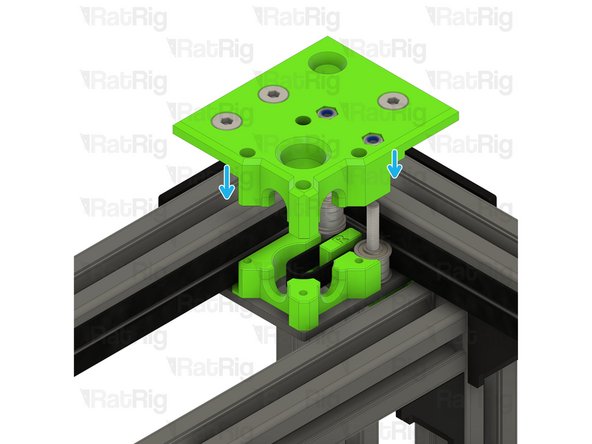
Install the xy_motor_cage_left_top assembly onto the frame as shown
-
Make sure the belt loop, created in Step 6, remains in the position shown
-
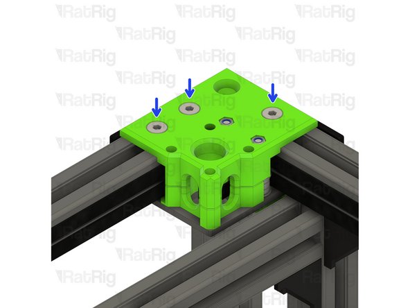
Tighten the three marked M6x14 screws to secure the CoreXY motor cage top to the frame
-
Take care not to over tighten the M6x14 screws as you can damage the printed part
-
Tighten the M5x40 screws to secure the bearing stacks into the CoreXY motor cage top
-
-
-
1x 20 Tooth 2GT Timing Pulley for 9mm Belt
-
1x 48mm NEMA17 Stepper Motor
-
4x M3x35 Cap Head Screw
-
-
-
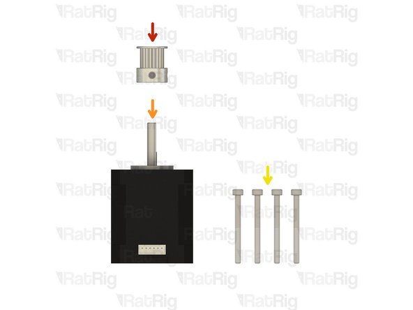
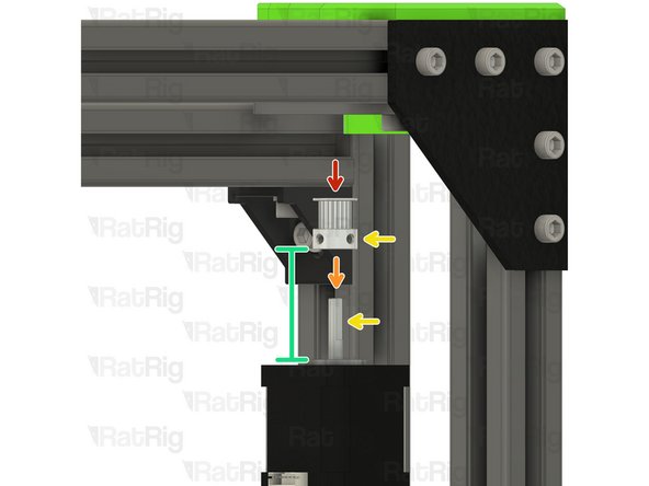
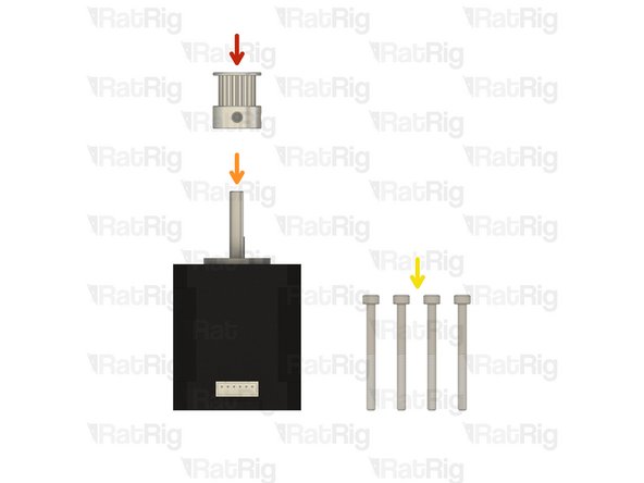
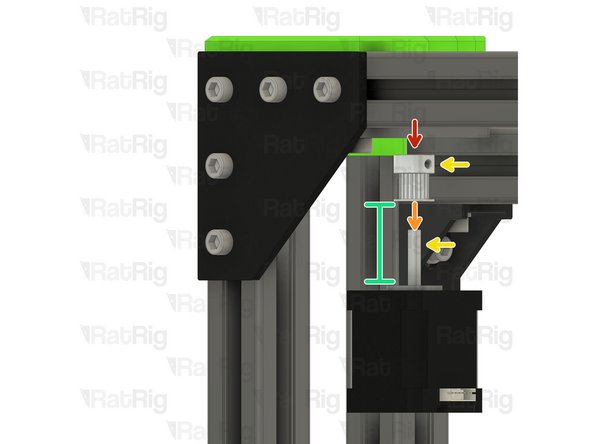
20 Tooth 2GT Timing Pulley for 9mm Belt
-
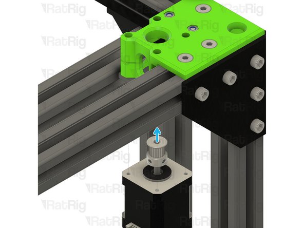
Install the timing pulley onto the NEMA17 shaft, oriented as shown
-
Align one of the M3 grub screws on the timing pulley so that it will tighten against the flat on the NEMA17 shaft
-
Position the timing pulley so the marked gap is 9.5mm
-
Slightly tighten one of the M3 grub screws to hold the timing pulley in position for now
-
The timing pulley will be aligned and fully secured in the next step
-
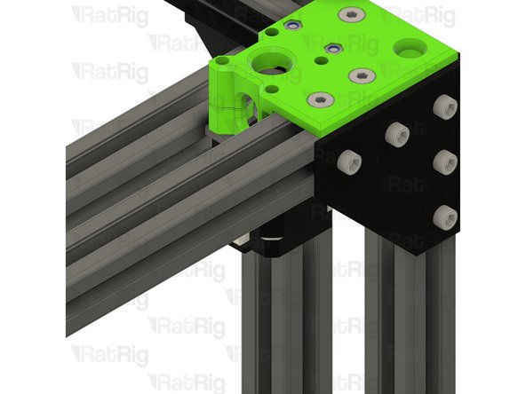
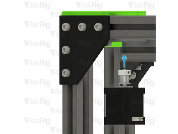
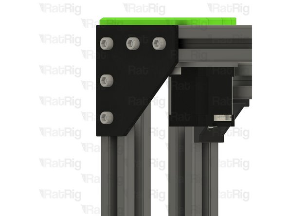
Position the NEMA17 motor up and into the motor cage from below, it will be secured in the next step
-
-
-
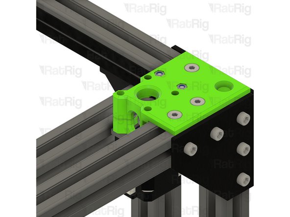
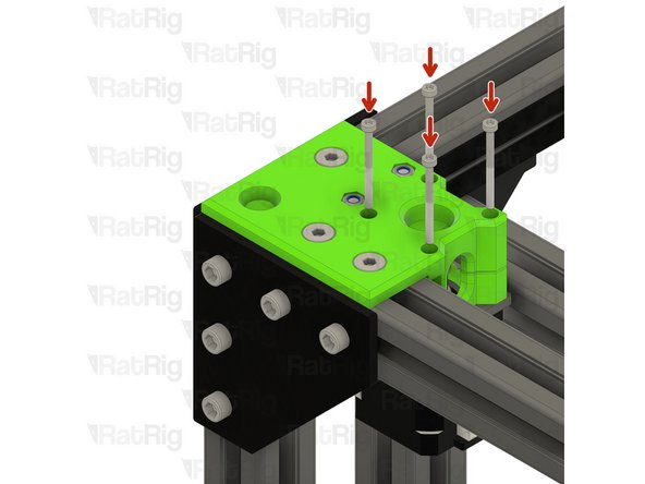
Insert the M3x35 screws into the xy_motor_cage_left_top as shown, and fasten them to secure the NEMA17 motor to the mount
-
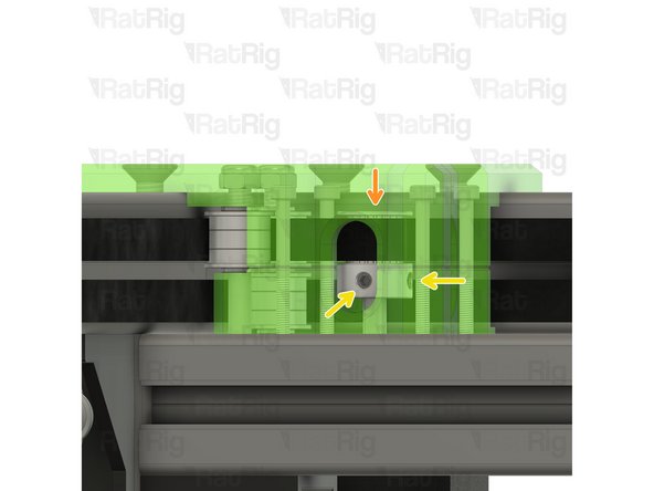
Check the alignment of the timing pulley, the belt should be on the middle of the pulley as shown
-
Adjust the pulley up or down if required to make sure the belt is in the middle of the pulley
-
Fasten both M3 grub screws to securely mount the timing pulley to the NEMA17 motor shaft
-
-
-
V-Core 3.1 Frame Assembly - Rear Right Corner
-
Right motor_plate assembly from Step 2
-
Install the right motor_plate assembly to the V-Core 3.1 frame as shown
-
Tighten the four M6x12 screws to secure the motor_plate assembly to the frame
-
Make sure the plate is fully seated against the 3030 extrusion before tightening the M6x12 screws
-
Insert two M5x40 Cap Head Screws into the motor_plate, as shown, in preparation for Step 14
-
-
-
3x M6x14 Countersink Screw
-
3x 3030 Drop-in T-Nut - M6
-
1x xy_motor_cage_bottom_right_3.1 Printed Part
-
1x xy_motor_cage_top_right_3.1 Printed Part
-
6x F695ZZ Ball Bearing
-
3x 695ZZ Ball Bearing
-
5x Mini Precision Shim
-
2x M5 Nylon Locking Hex Nut
-
-
-
V-Core 3.1 Frame Assembly - Rear Right Corner
-
Install the following components in the order shown in the image:
-
Mini Precision Shim
-
F695ZZ Ball Bearing (Flange at the bottom)
-
695ZZ Ball Bearing
-
F695ZZ Ball Bearing (Flange at the top)
-
-
-
xy_motor_cage_bottom_right_3.1 Printed Part
-
Place the xy_motor_cage_bottom_right_3.1 printed part as shown
-
The xy_motor_cage_bottom_right part will just sit on the plate for now, it will be secured in Step 20
-
-
-
Loose end of the bottom CoreXY belt
-
Form a loop as shown, with the toothed side of the belt facing the frame and the smooth side facing the bearing stacks. This will be used to engage with the NEMA17 motor pulley
-
Position the bottom belt as shown
-
Loose end of the top CoreXY belt
-
Slot this end of the top CoreXY belt around the top bearing stack as shown
-
Make sure that both belts match the third image before proceeding
-
-
-
3030 Drop-in T-Nut - M6
-
xy_motor_cage_top_right_3.1 Printed Part
-
M6x14 Countersink Screw
-
Loosely thread a 3030 T-Nut onto each of the M6x14 screws. Do not tighten them at this point.
-
M5 Nylon Locking Hex Nut
-
Install the xy_motor_cage_right_top assembly onto the frame as shown
-
Tighten the three marked M6x14 screws to secure the CoreXY motor cage top to the frame
-
Tighten the M5x40 screws, on the underside, to secure the bearing stacks into the CoreXY motor cage top
-
-
-
1x 20 Tooth 2GT Timing Pulley for 9mm Belt
-
1x 48mm NEMA17 Stepper Motor
-
4x M3x35 Cap Head Screw
-
-
-
20 Tooth 2GT Timing Pulley for 9mm Belt
-
Install the timing pulley onto the NEMA17 shaft, oriented as shown
-
Align one of the M3 grub screws on the timing pulley so that it will tighten against the flat on the NEMA17 shaft
-
Position the timing pulley so the marked gap is 3mm
-
Slightly tighten one of the M3 grub screws to hold the timing pulley in position for now
-
The timing pulley will be aligned and fully secured in the next step
-
Position the NEMA17 motor up and into the motor cage from below, it will be secured in the next step
-
-
-
Insert the M3x35 screws into the xy_motor_cage_right_top as shown, and fasten them to secure the NEMA17 motor to the mount
-
Check the alignment of the timing pulley, the belt should be on the middle of the pulley as shown
-
Adjust the pulley up or down if required to make sure the belt is in the middle of the pulley
-
Fasten both M3 grub screws to securely mount the timing pulley to the NEMA17 motor shaft
-
Cancel: I did not complete this guide.
33 other people completed this guide.


