
-
-
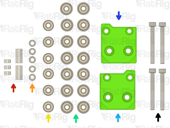
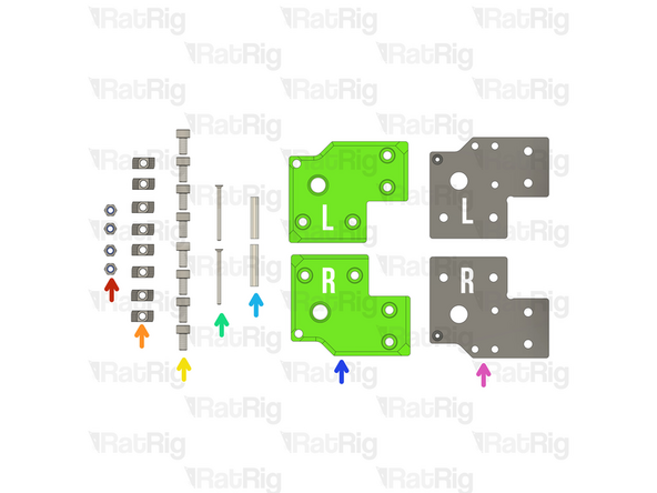
Right Stepper motor plate assembly from Step 27 of chapter 01.Frame assembly
-
Left Stepper motor plate assembly from Step 27 of chapter 01.Frame assembly
-
2x Nema 17 Stepper motor - HT - 48mm
-
2x 20 Tooth 2GT Timing Pulley for 9mm Belt
-
6x M3x6 Countersink Screws
-
-
-
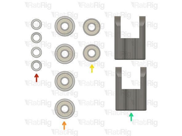
3x Aluminium spacer 5x8x4mm + 1x Aluminium spacer 5x8x14mm + Aluminium spacer 5x8x17mm
-
5x Mini precision shim 8x5x1mm
-
6x Ball bearing 695ZZ
-
14x Ball bearing F695ZZ
-
Right vc4_motor_spacer
-
Left vc4_motor_spacer
-
4x M5x45 Cap Head Screws
-
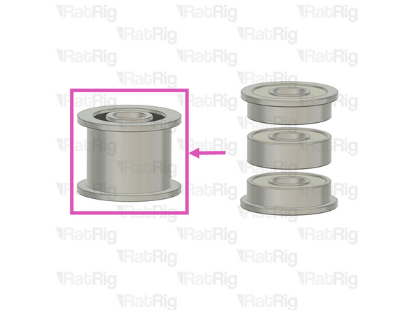
6x Heavy-Duty Idler – The latest V-Core 4 kits now feature these heavy-duty idlers as a replacement for the previously used bearing stack assemblies.
-
-
-
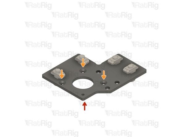
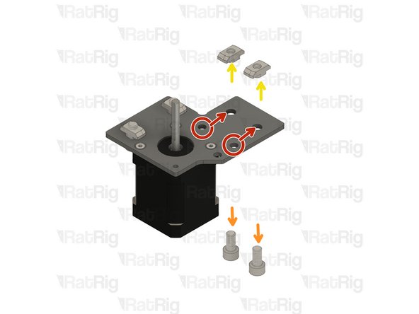
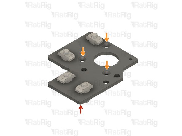
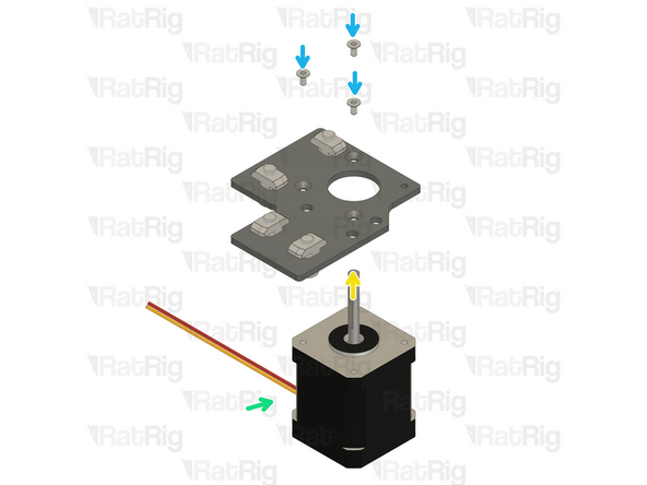
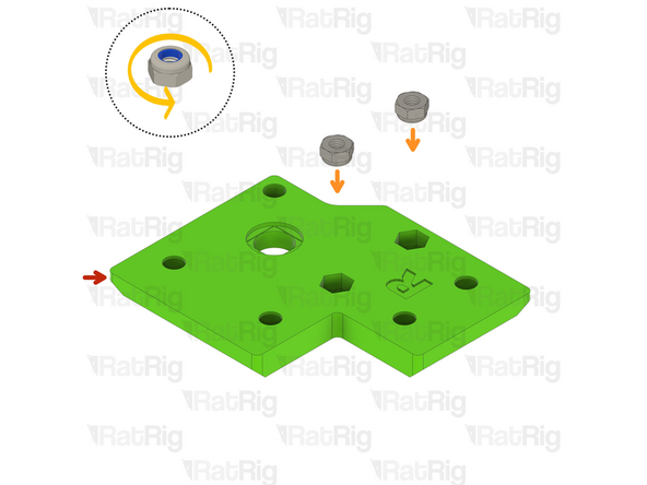
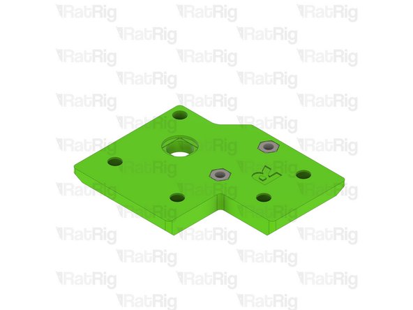
Right Stepper motor plate assembly from Step 27 of chapter 01.Frame assembly
-
Ensure the t-nuts are on the same side as the countersink bores.
-
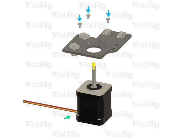
Nema 17 Stepper motor - HT - 48mm
-
Be mindful of the cable orientation, it should replicate the image.
-
3x M3x6 Countersink Screws
-
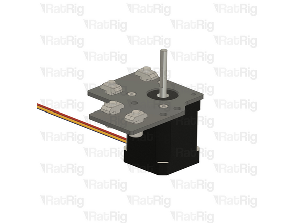
Insert the M3x6 screws into the Right Stepper motor plate assembly as shown, and fasten them to secure the NEMA17 motor.
-
-
-
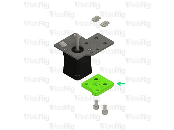
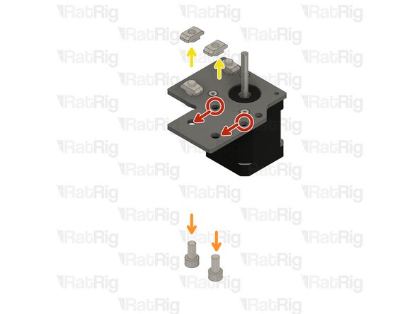
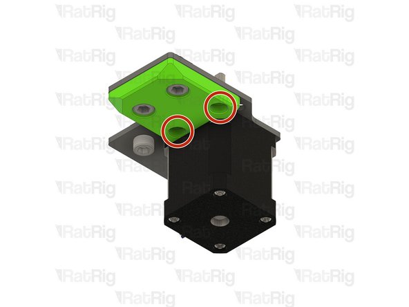
Refer to the side of the assembly which has the M5 holes
-
Remove the two M6x12 Cap Head Screws
-
Remove the two 3030 Drop-in T-Nut - M6
-
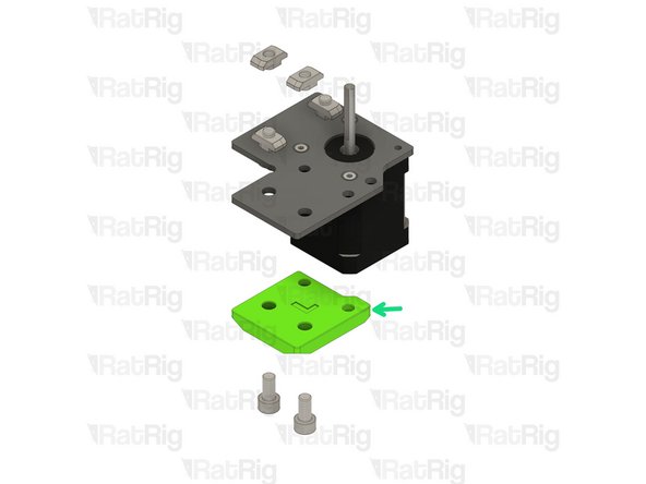
Right vc4_motor_spacer
-
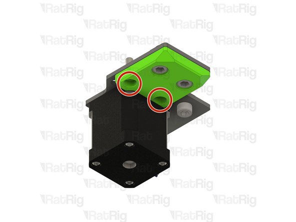
Install the printed part next to the nema 17 stepper motors, and make sure the holes are aligned.
-
Insert the two M6x12 Cap Head Screws
-
Insert the two 3030 Drop-in T-Nut - M6
-
Loosely thread a 3030 T-Nut onto each of the M6x12 screws. Do not tighten them at this point.
-
-
-
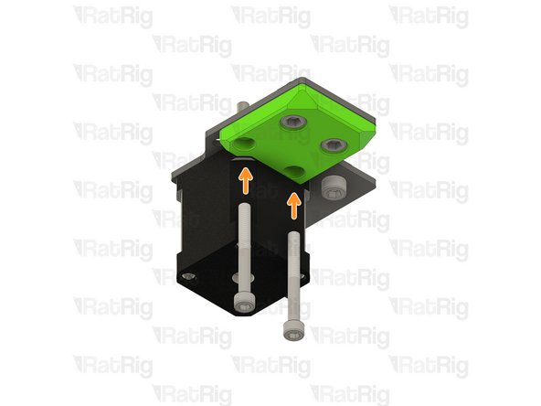
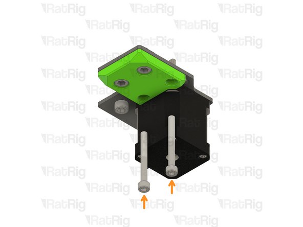
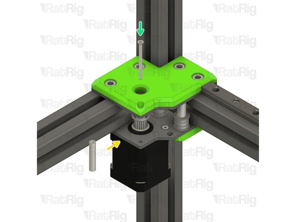
Ensure the right vc4_motor_spacer printed part is aligned with the plate
-
Insert the M5x45 Cap Head Screws all the way
-
Once inserted, the printed part should be able to hold them in place
-
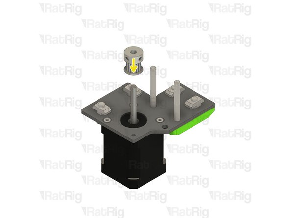
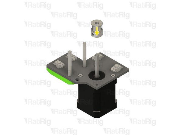
Install the timing pulley onto the NEMA17 shaft, oriented as shown
-
The timing pulley will be aligned and fully secured in a later step.. Do not tighten the M3 grub screws
-
-
-
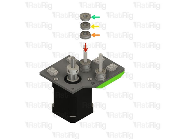
Install the following components in the order shown in the image:
-
Mini Precision Shim
-
F695ZZ Ball Bearing (Flange at the bottom)
-
695ZZ Ball Bearing
-
F695ZZ Ball Bearing (Flange at the top)
-
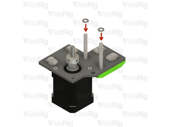
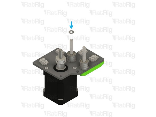
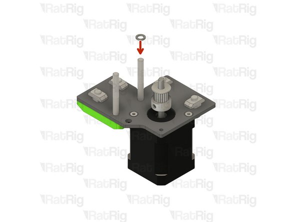
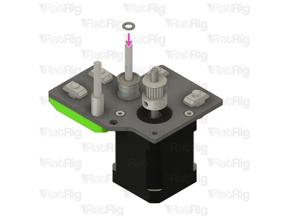
Insert a Mini Precision Shim on the rear M5x45 Screw
-
-
-
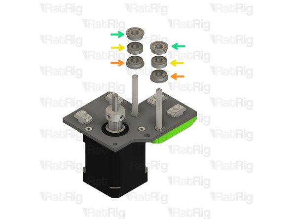
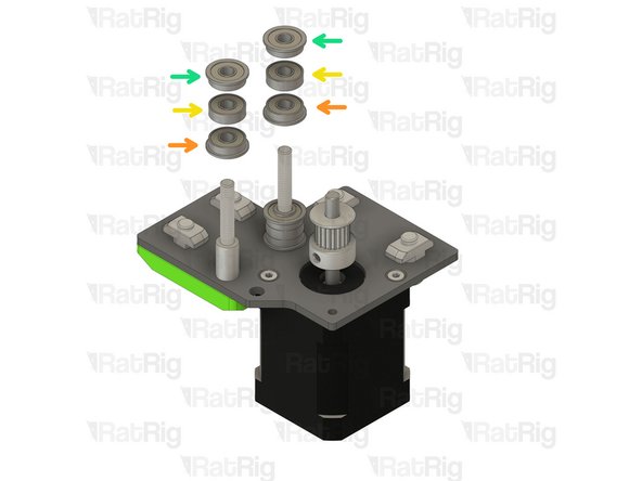
Install the following components on the rear M5x45 Screw in the order shown in the image:
-
F695ZZ Ball Bearing (Flange at the bottom)
-
695ZZ Ball Bearing
-
F695ZZ Ball Bearing (Flange at the top)
-
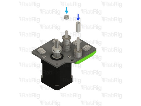
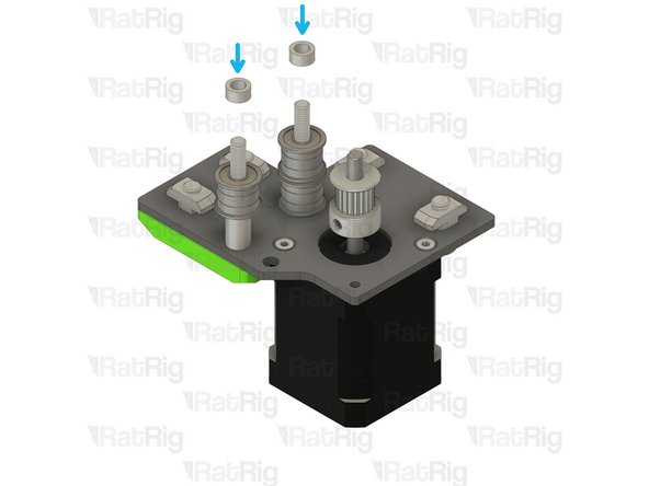
Install an Aluminium spacer 5x8x4mm on the rear M5x45 Screw
-
Install an Aluminium spacer 5x8x17mm on the front M5x45 Screw
-
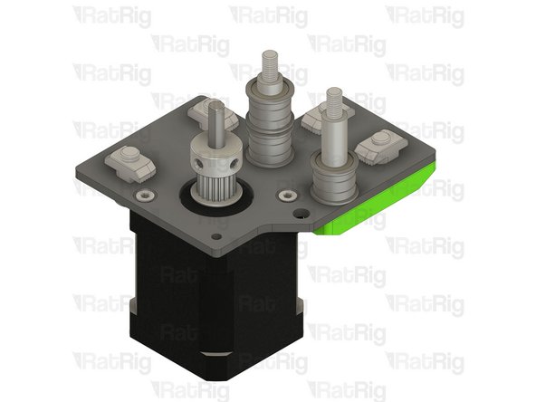
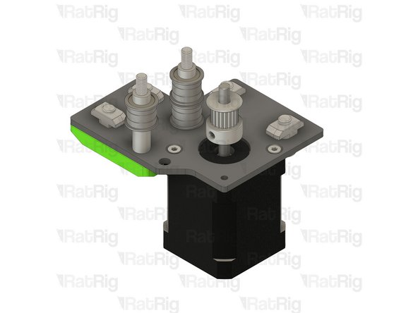
Set the assembly aside, let's assemble the left stepper motor.
-
-
-
Left Stepper motor plate assembly from Step 27 of chapter 01.Frame assembly
-
Ensure the t-nuts are on the same side as the countersink bores.
-
Nema 17 Stepper motor - HT - 48mm
-
Be mindful of the cable orientation, it should replicate the image.
-
3x M3x6 Countersink Screws
-
Insert the M3x6 screws into the Right Stepper motor plate assembly as shown, and fasten them to secure the NEMA17 motor.
-
-
-
Refer to the side of the assembly which has the M5 holes
-
Remove the two M6x12 Cap Head Screws
-
Remove the two 3030 Drop-in T-Nut - M6
-
Left vc4_motor_spacer
-
Install the printed part next to the nema 17 stepper motors, and make sure the holes are aligned.
-
Insert the two M6x12 Cap Head Screws
-
Insert the two 3030 Drop-in T-Nut - M6
-
Loosely thread a 3030 T-Nut onto each of the M6x12 screws. Do not tighten them at this point.
-
-
-
Ensure the left vc4_motor_spacer printed part is aligned with the plate
-
Insert the M5x45 Cap Head Screws all the way
-
Once inserted, the printed part should be able to hold them in place
-
Install the timing pulley onto the NEMA17 shaft, oriented as shown
-
The timing pulley will be aligned and fully secured in a later step. Do not tighten the M3 grub screws
-
-
-
Insert a Mini Precision Shim on the rear M5x45 Screw
-
Install an Aluminium spacer 5x8x14mm on the front M5x45 Screw
-
Install the following components on the rear M5x45 Screw in the order shown in the image:
-
F695ZZ Ball Bearing (Flange at the bottom)
-
695ZZ Ball Bearing
-
F695ZZ Ball Bearing (Flange at the top)
-
Insert a Mini Precision Shim on the rear M5x45 Screw
-
-
-
Install the following components in the order shown in the image:
-
F695ZZ Ball Bearing (Flange at the bottom)
-
695ZZ Ball Bearing
-
F695ZZ Ball Bearing (Flange at the top)
-
Aluminium spacer 5x8x4mm
-
Set the assembly aside. it will be used in a few steps
-
-
-
4x M5 Hex Locking nut
-
8x 3030 Drop-in T-Nut - M6
-
8x M6x12 Cap Head Screws
-
2x M3x40 Countersink Screw
-
2x Aluminium Spacer 3x6x30mm
-
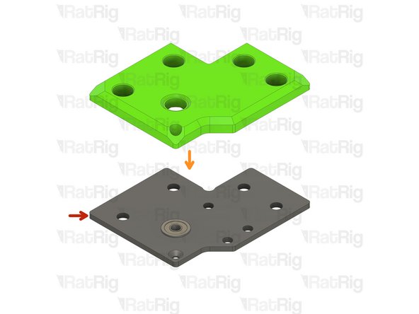
The metal plates are not marked with "R" or "L" Please refer to the orientation to help identify them.
-
vc4_trim_coreXY_right and vc4_trim_coreXY_left
-
vc4_xy_motor_upper_right and vc4_xy_motor_upper_left
-
-
-
vc4_trim_coreXY_right
-
2x M5 Hex Locking nut
-
Insert the M5 Hex Locking nut upside down.
-
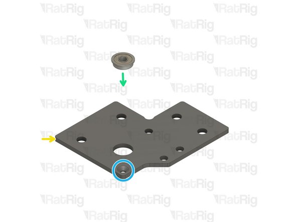
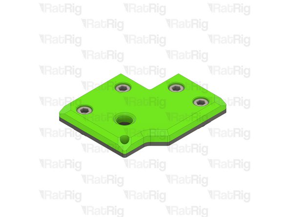
vc4_xy_motor_upper_right
-
Ball bearing F695ZZ
-
Insert the Ball bearing F695ZZ with the flange at the top
-
Ensure the bearing flange is on the same side as the countersink bore.
-
-
-
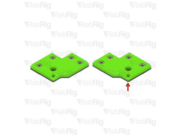
vc4_xy_motor_upper_right assembly
-
vc4_trim_coreXY_right assembly
-
Insert the four M6x12 Cap Head Screws
-
Insert the four 3030 Drop-in T-Nut - M6
-
Loosely thread a 3030 T-Nut onto each of the M6x12 screws. Do not tighten them at this point.
-
-
-
Repeat Steps 14 and 15 and complete the left assembly
-
-
-
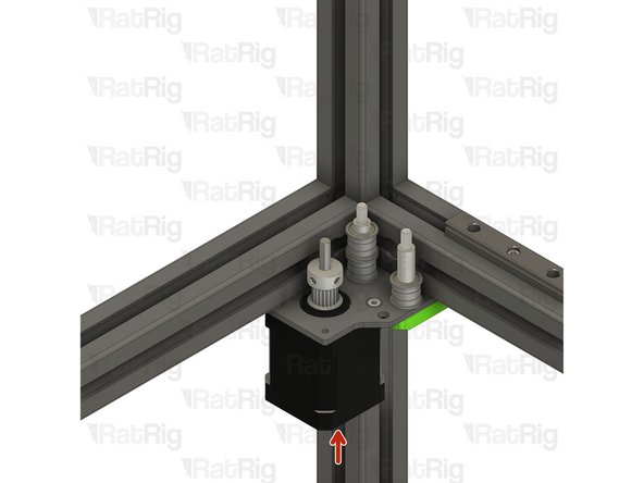
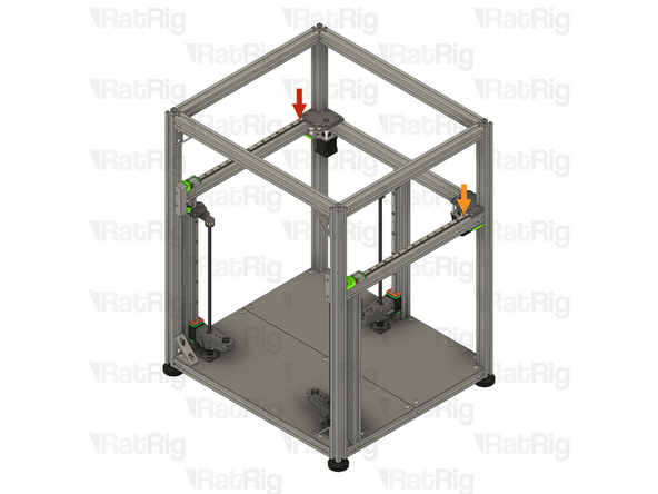
Place the right stepper motor assembly from Step 7 in the frame
-
-
-
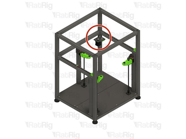
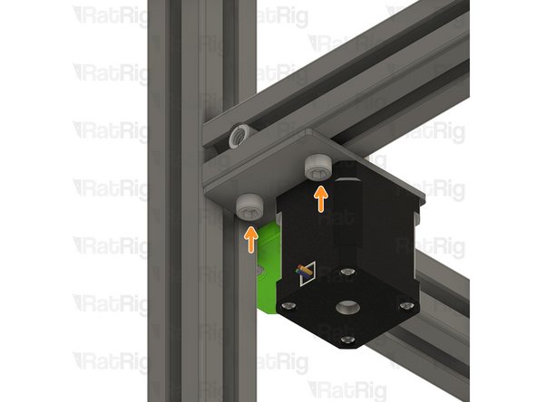
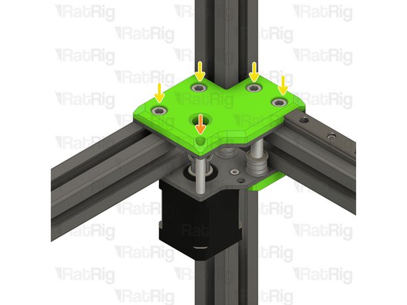
Install the right stepper motor assembly to the V-Core 4 frame as shown
-
Tighten the four M6x12 screws to secure the motor_plate assembly to the frame
-
Make sure the plate is fully seated against the 3030 extrusion before tightening the M6x12 screws
-
Take care not to over tighten the M6x12 screws as you can damage the printed parts
-
-
-
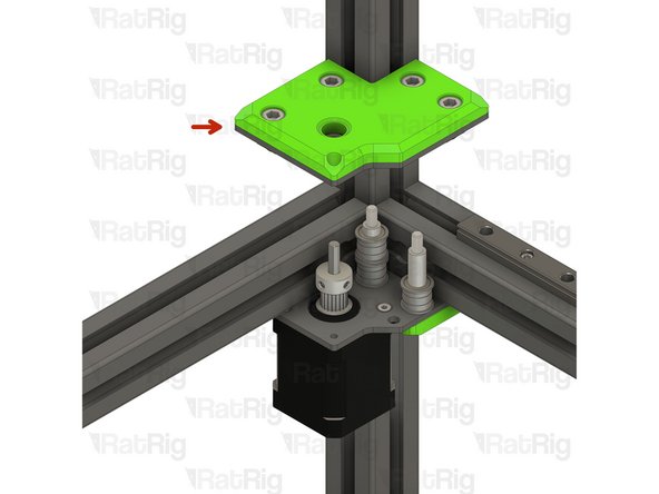
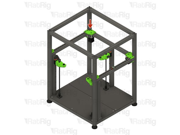
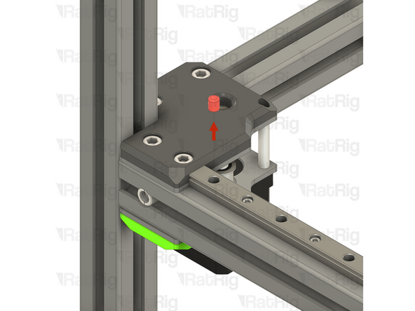
Right top stepper motor assembly from Step 15
-
Make sure the plate is fully seated against the 3030 extrusion.
-
Insert the Aluminium Spacer 3x6x30mm between the top and bottom plates
-
Insert the M3x40 countersink screw through the top plate, the aluminium spacer 3x6x30mm, and the bottom plate. Do not thread it to the stepper motor at this stage
-
-
-
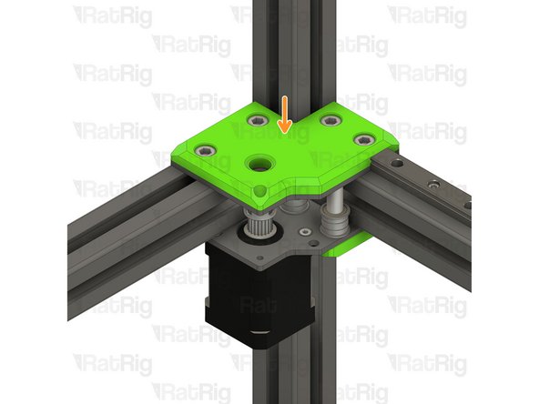
Progressively tighten both M5x45 screws, alternating between them, so the top plate assembly is pulled down uniformly.
-
Take care not to over tighten the M5x45 screws as you can damage the printed parts
-
Tighten the M3x40 countersink screw to to nema 17 stepper motor thread.
-
Tighten the four M6x12 screws to secure the motor_plate assembly to the frame
-
Make sure the plate is fully seated against the 3030 extrusion before tightening the M6x12 screws
-
Take care not to over tighten the M6x12 screws as you can damage the printed parts
-
-
-
Repeat Steps 17 to 20 and install the left stepper motor to the V-Core 4 frame.
-
-
-
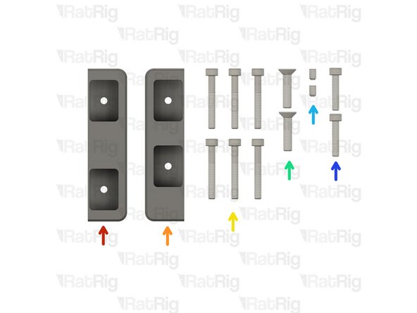
Rat Rig V-Core 4.0 - Tensioner Body - Right v1.0
-
Rat Rig V-Core 4.0 - Tensioner Body - Left v1.0
-
6x M4x30 Cap Head Screw
-
2x M5x22 Countersink Screw
-
2x M4x6 Set Screw
-
2x M4x20 Cap Head Screw
-
-
-
4x Mini precision shim 8x5x1mm
-
4x Ball bearing F695ZZ
-
2x Ball bearing 695ZZ
-
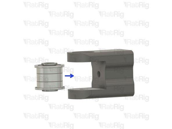
2x Rat Rig V-Core 4.0 - Tensioner Arm v1.0
-
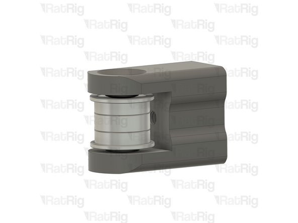
2x Heavy-Duty Idler – The latest V-Core 4 kits now feature these heavy-duty idlers as a replacement for the previously used bearing stack assemblies.
-
-
-
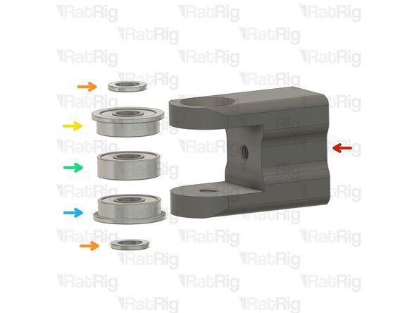
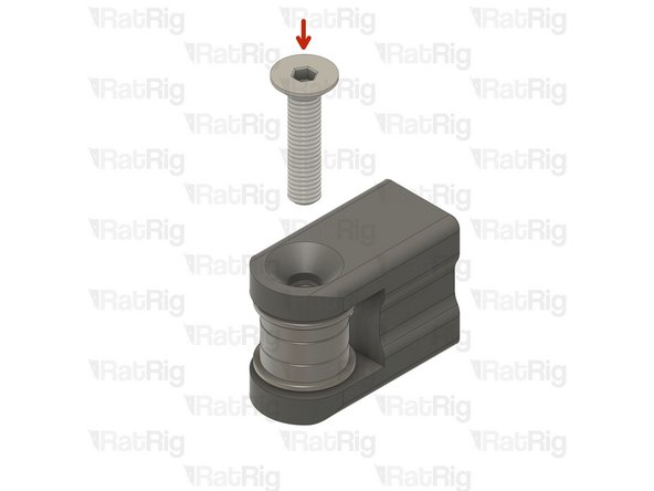
Rat Rig V-Core 4.0 - Tensioner Arm v1.0
-
Install the following components in the order shown in the image:
-
Mini Precision Shim
-
F695ZZ Ball Bearing (Flange at the top)
-
695ZZ Ball Bearing
-
F695ZZ Ball Bearing (Flange at the bottom)
-
Mini Precision Shim
-
-
-
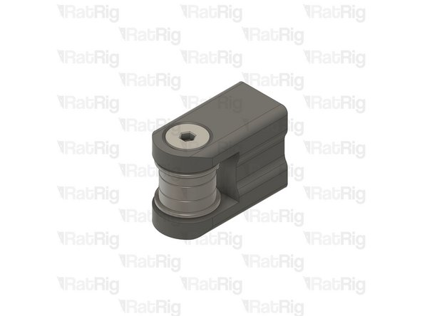
Insert the M5x22 Countersink Screw and tighten it to secure the assembly.
-
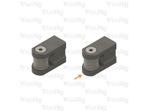
Repeat Steps 25 and 26 to assemble another tensioner arm
-
-
-
Rat Rig V-Core 4.0 - Tensioner Body - Right v1.0
-
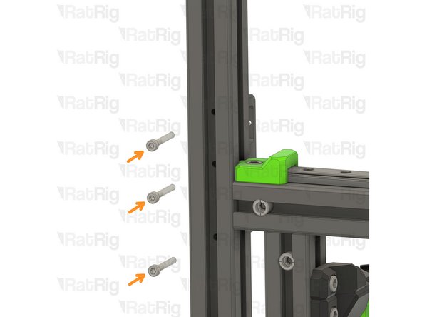
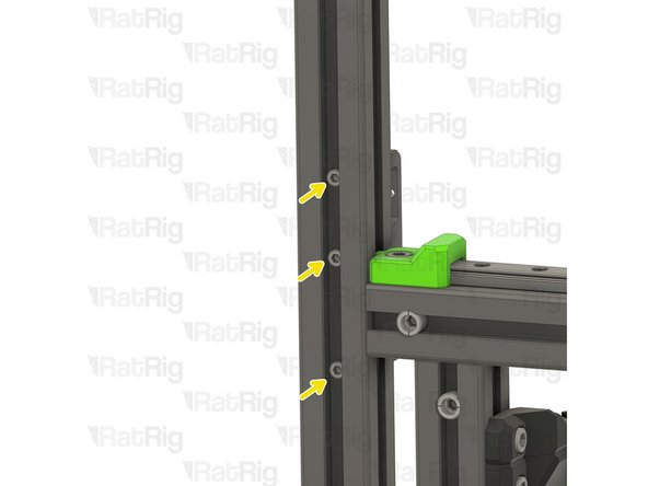
3x M4x30 Cap Head Screws
-
Insert the screws through the holes on the V-Core 4 frame extrusion and thread them in the Tensioner Body - Right v1.0.
-
Tighten the M4x30 cap head screws.
-
-
-
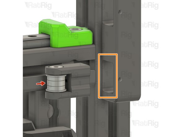
Front tensioner arm assembly from Step 26
-
Insert the tensioner arm in the lower slot of the tensioner body.
-
Make sure the tensioner arm has cleared the hole on the tensioner body.
-
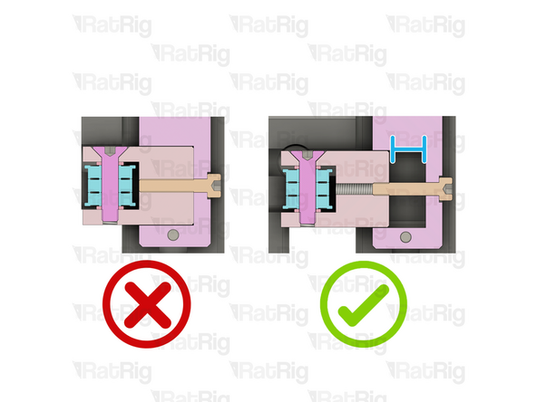
M4x20 Cap Head Screw
-
Insert the screw trough the tensioner body and lightly thread it to the tensioner arm.
-
The M4x20 screw must be partially, but not fully, threaded into the tensioner arm. This allows the largest possible range for tensioning the belts further in the guide.
-
-
-
M4x6 Set Screw
-
Tighten the Screw to secure the tensioner arm in place
-
Repeat Steps 27 to 29 and assemble the Left front tensioner
-
-
-
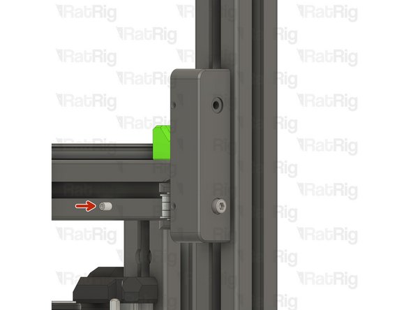
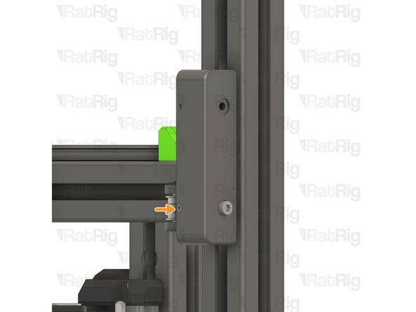
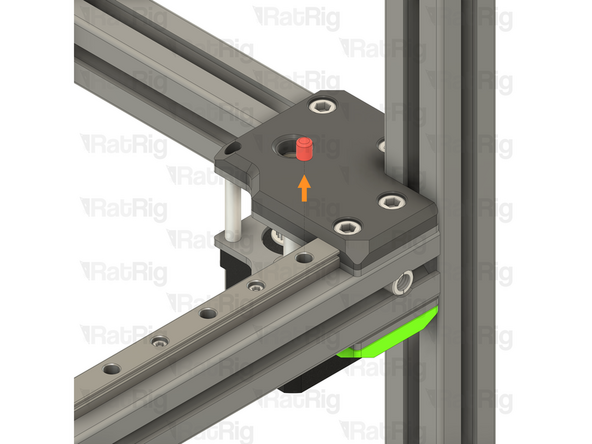
If you installed the Y-axis linear rail plastic stops in step 12 and step 14 of the Y-Axis Assembly guide, remove them now
-
Left-hand Y-axis linear rail plastic stop
-
Right-hand Y-axis linear rail plastic stop
-
The plastic stops are no longer required and can be discarded
-


Cancel: I did not complete this guide.
10 other people completed this guide.
