
-
-
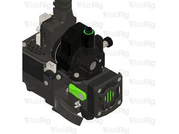
Orbiter 2 smart sensor
-
1x M3x25 Button head (included in the orbiter 2 smart sensor box)
-
1x M3 washer (M3x6x0.5) (included in the orbiter 2 smart sensor box)
-
1x M3x16mm Hex Spacer
-
-
-
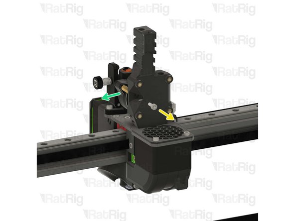
Remove the top right M3 Button head screw, it will not be used.
-
Remove the lower left M3 button head screw by 5-8mm.
-
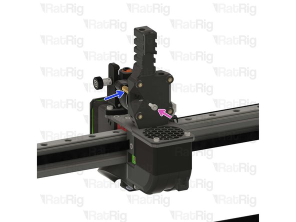
Remove the PTFE retaining clip.
-
Remove the PTFE locking mechanism by pulling it upwards.
-
-
-
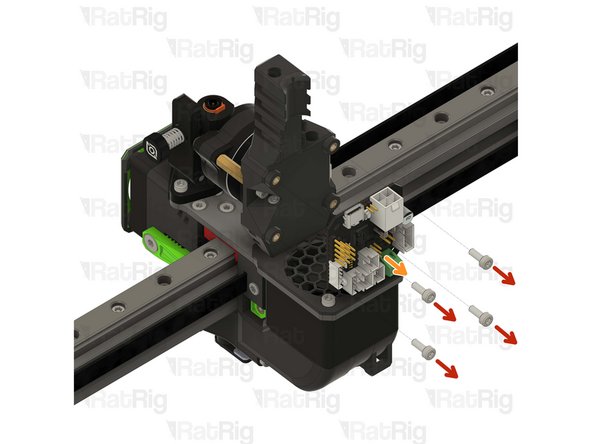
Remove the toolboard screws
-
If you are careful, there is no need to disconnect the wires from the toolboard.
-
Partially remove the toolboard.
-
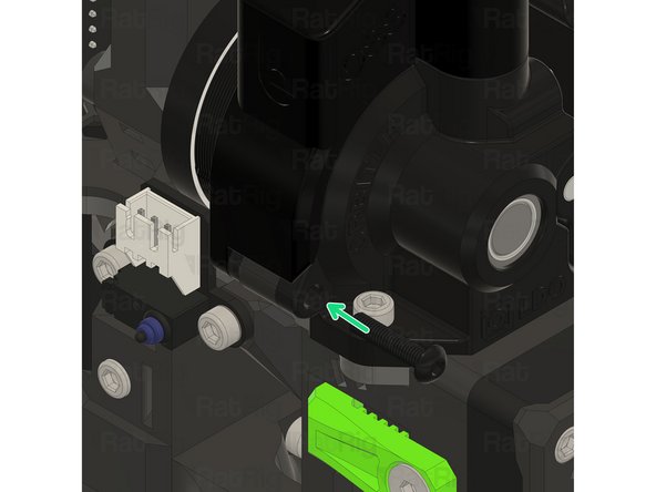
Remove the M3 Cap Head Screw holding the M3 Hex spacer.
-
Remove the M3 Hex spacer. (It will not be used again).
-
Install the new M3x16mm Hex Spacer.
-
Re-install the M3 Cap Head Screw.
-
Re-install the toolboard and its screws.
-
-
-
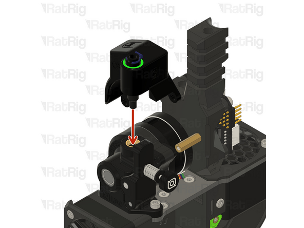
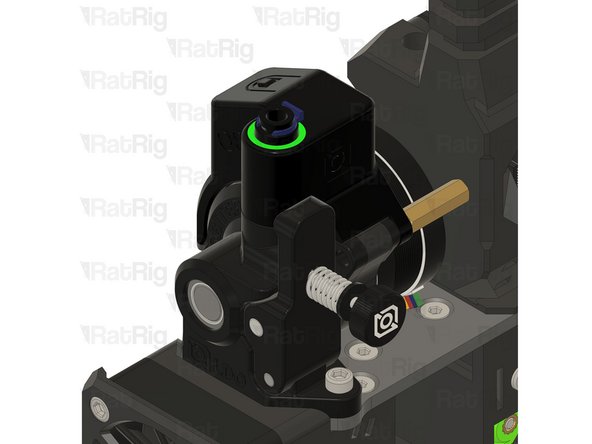
Insert the orbiter 2 smart sensor inside the PTFE hole, carefully align it.
-
Do not force it in, you may damage the orbiter 2 smart sensor.
-
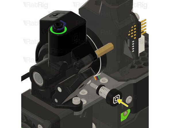
Remove the tensioning screw and open the orbiter arm.
-
-
-
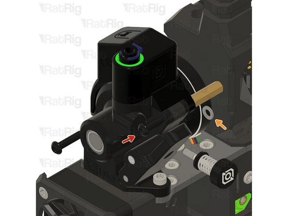
Thread the M3x25 Button head screw half way.
-
Insert the M3 washer between the orbiter 2 smart sensor and the M3 Hex spacer.
-
Fully tighten the M3x25 Button head screw.
-
Tighten the lower left M3 Button head, ensuring it is fed trough the orbiter 2 smart sensor hole.
-
-
-
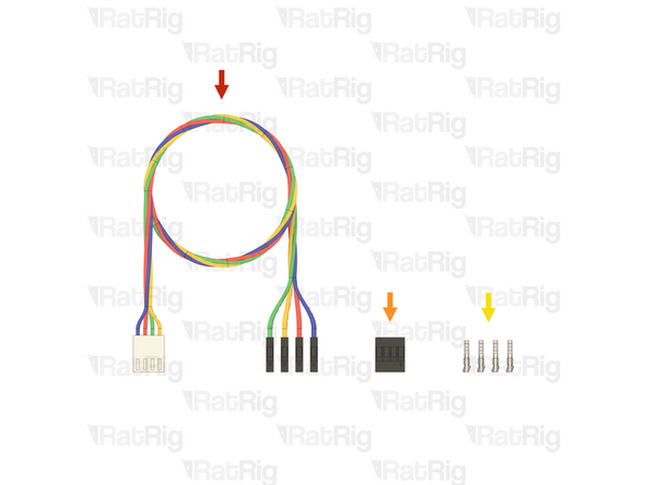
The following part is included in the Orbiter 2 smart sensor box (SKU: HW3990EC)
-
1x Orbiter 2 Smart Sensor Wiring Harness
-
1x Connector - 4 Pin - Dupont Housing 4x1 - 2.54mm (SKU: HW4160EC )
-
4x Crimp - Dupont 2.54mm Female (SKU: HW4161EC)
-
-
-
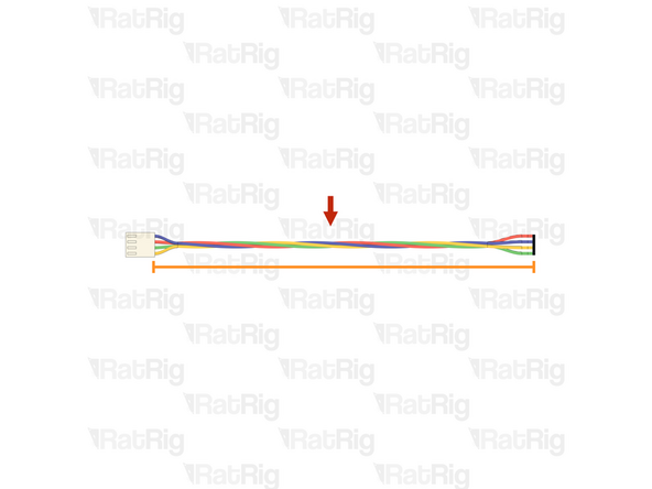
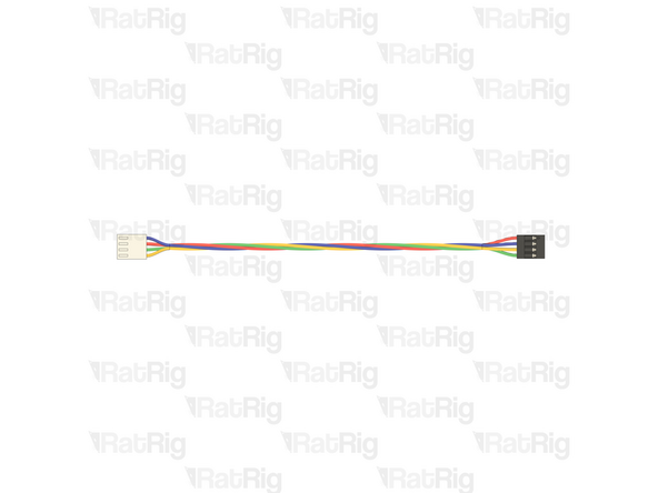
Orbiter 2 Smart Sensor Wiring Harness
-
Measure 160mm from the back of the single white connector
-
Use wire cutters to cut the wiring harness the measured length
-
The remaining wire can be discarded, it is no longer needed
-
Strip 2mm of the insulation from the end of each of the bare wires
-
-
-
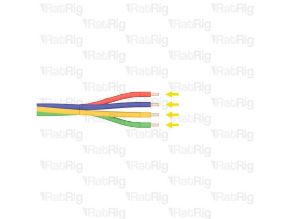
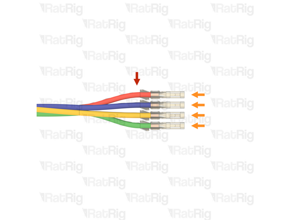
Prepared wires from the previous step
-
Crimp - Dupont 2.54mm Female
-
Crimp a female Dupont terminal onto each of the four stripped wires
-
Before proceeding, verify that all four crimp terminals are correctly crimped to the wires
-
-
-
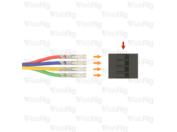
Connector - 4 Pin - Dupont Housing 4x1 - 2.54mm
-
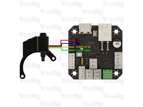
Please note: The wiring colour shown may not match your Orbiter smart sensor harness. It is very important to use the provided wiring diagram to correctly assembly the cable. Do not blindly follow the wire colours
-
Make sure the wires are inserted into the correct positions. Incorrect wiring will damage the Orbiter smart sensor, toolboard, and other electronics
-
Insert the crimped terminals into the Dupont connector, using the wiring diagram provided. The crimp terminals will "click" when fully inserted
-
-
-
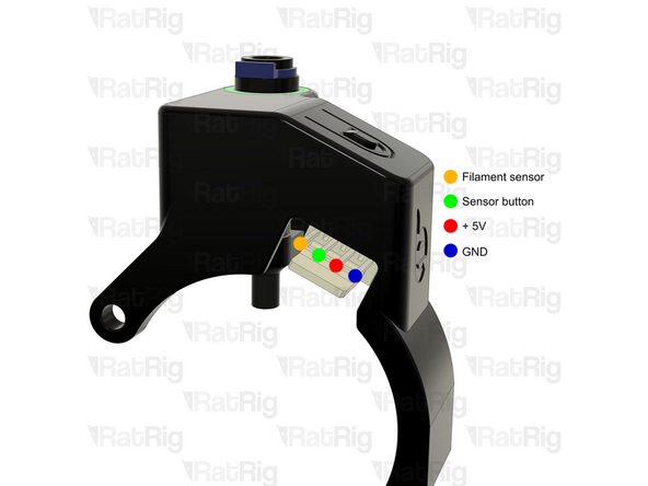
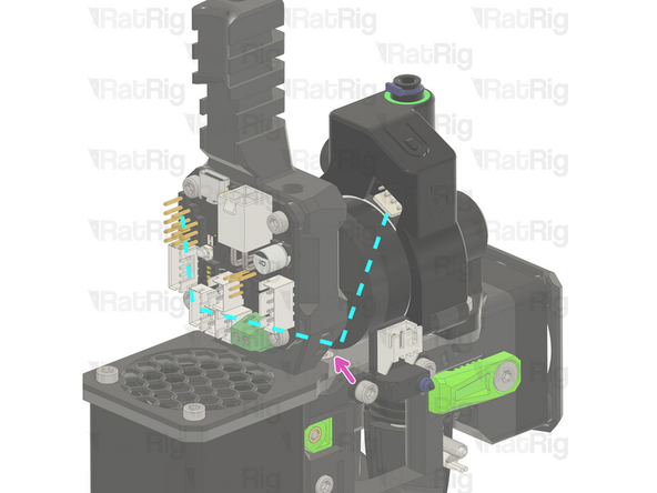
Connect the cable prepared in the previous steps to the Orbiter smart sensor to the EBB42 toolboard
-
Pay close attention to the connection to the EBB42 toolboard. The Dupont connector is not keyed and can be installed backwards. Verify the connection before continuing
-
Route the cable as shown, using zip ties to secure it in place.
-
For more information about the Orbiter Smart Sensor V2 - Click Here
-
-
-
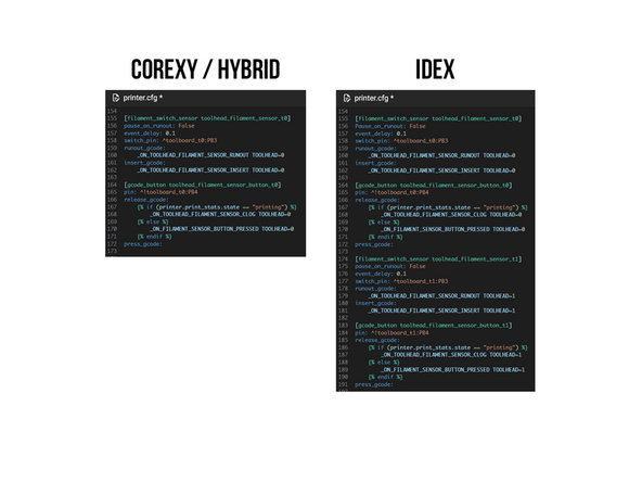
Test!
-
Click here to be redirected to the config page where you can COPY the text.
-
For more information about the Orbiter Smart Sensor V2 - Click Here
-


Cancel: I did not complete this guide.
One other person completed this guide.
