
-
-
If you intend on installing a base panel on your V-Core 3, it is highly recommended to do so before continuing.
-
Follow Step 39 of the enclosure assembly guide to prepare the base panel
-
Follow Step 48 of the enclosure assembly guide to install the base panel
-
Once the panel is installed, continue with this guide
-
-
-
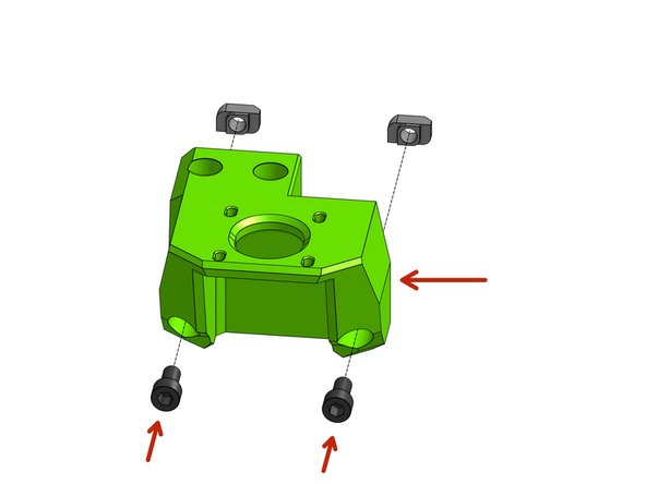
Thread the Cap Head Screws M6x20 screws through the lead_screw_motor_cage_front part
-
Attach the 3030 M6 T-nuts
-
Repeat the same twice - in the case of those Z mounts the left and right assemblies are the same
-
-
-
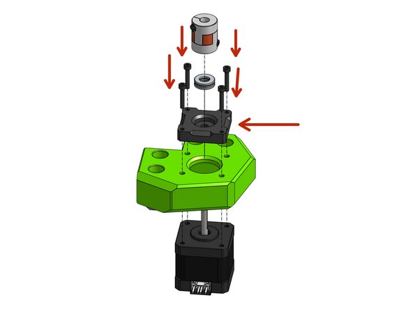
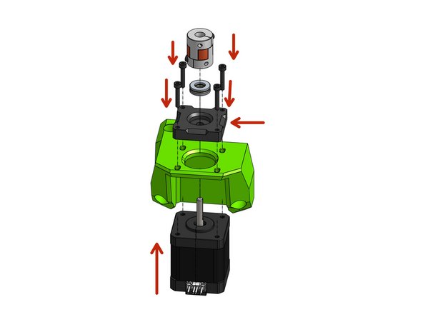
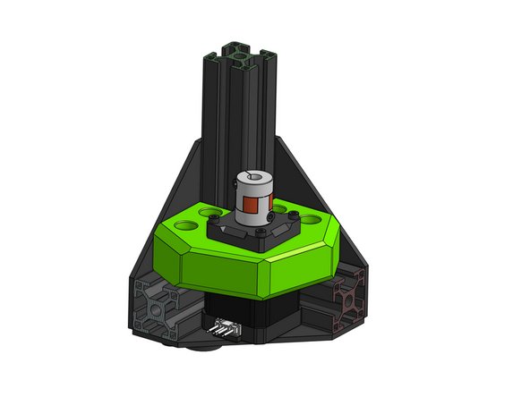
Attach the NEMA17 stepper motor to the printed part through the pillow_block part with the Cap Head M3x18 screws
-
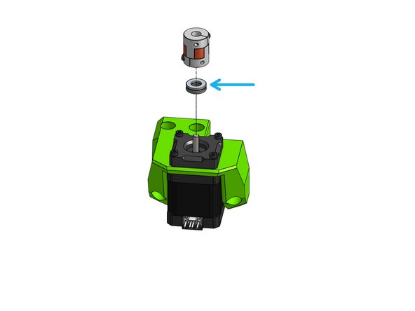
Apply a small amount of bearing grease to the thrust bearing. this will decrease wear and prolong the life of the bearing. Regular servicing should include cleaning and replacing grease.
-
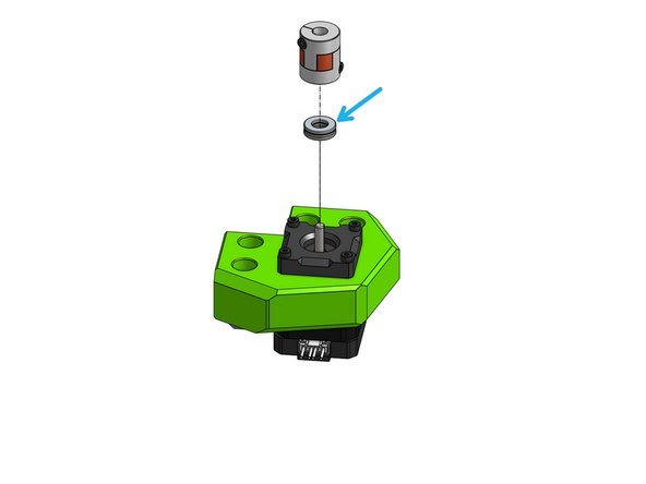
Insert the thrust bearing into the pillow block
-
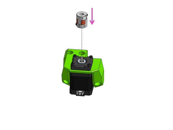
Attach the coupler
-
The coupler needs to rest on the thrust bearing for the bearing to take the load off the motor shaft. Use the coupler to press the bearing down into the printed part until you hear a "click".
-
Repeat this step for the other side of the printer
-
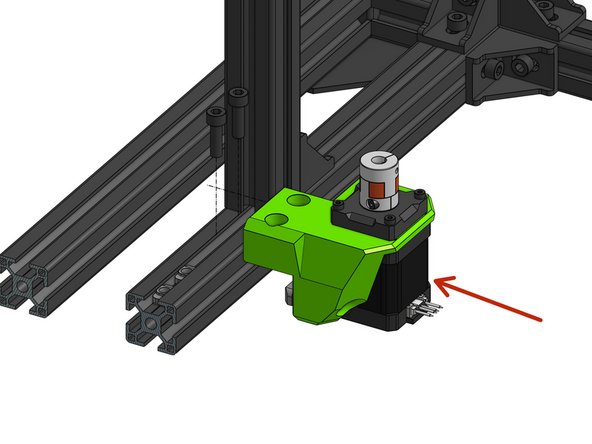
Be mindful about how the motor wires are aligned, rotate the motor if needed. Routing the wires to the back of the printer gives the opportunity for a clean build
-
-
-
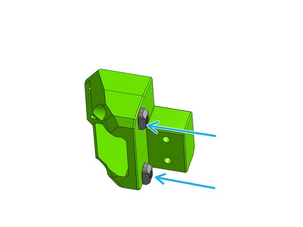
Thread the two Cap Head M6x12 screws through the lead_screw_motor_cage_back printed part
-
Attach the 3030 M6 T-nuts on the back
-
-
-
Attach the NEMA17 stepper motor to the printed part through the pillow_block part with the Cap Head M3x18 screws
-
Apply a small amount of bearing grease to the thrust bearing. this will decrease wear and prolong the life of the bearing. Regular servicing should include cleaning and replacing grease.
-
Insert the thrust bearing into the pillow block
-
Attach the coupler
-
The coupler needs to rest on the thrust bearing for the bearing to take the load of the motor shaft
-
-
-
If you want to install a bottom panel: DO IT NOW, before you install Z motor mounts
-
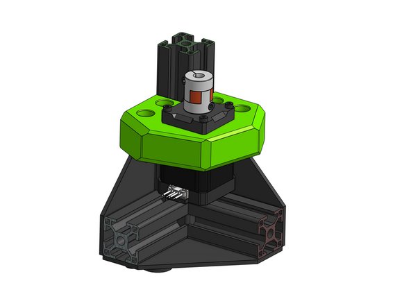
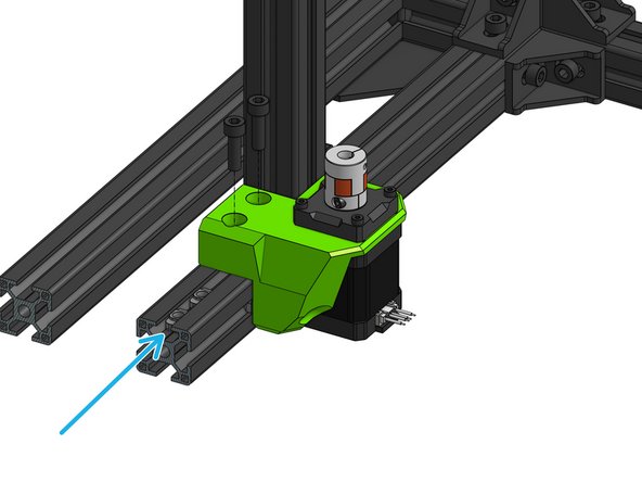
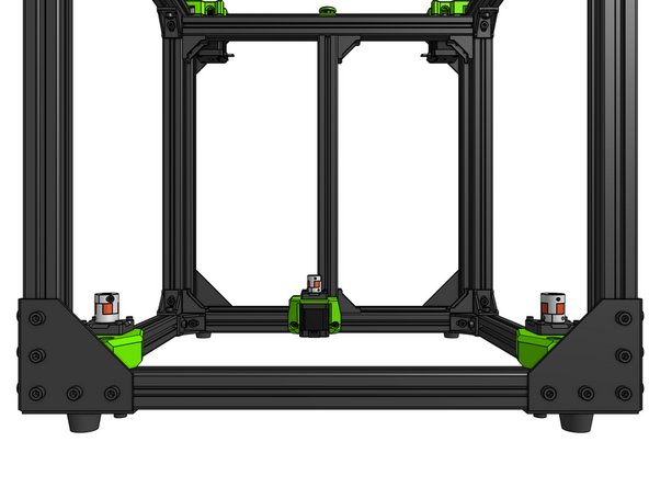
Put the assembly in the bottom-front corner of the frame
-
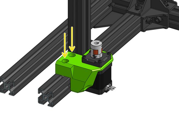
Loosely bolt the assembly
-
You'll likely notice there's room for adjustment - this will be important later
-


Cancel: I did not complete this guide.
47 other people completed this guide.
