Steps
27
- 04. Rat Rig Toolhead V2.0 27 steps

In Progress
This guide is currently being written. Reload periodically to see the latest changes.

Private
This guide will not appear in search results and can only be viewed by team members!
Quiz
0
Introduction
This guide provides a thorough overview of the disassembly of the EVA3, the preparation of the V-Core 3.1 frame, and the installation procedure for the Rat Rig toolhead V1.0 Upgrade Kit.
The Rat Rig Toolheads are streamlined to be used specifically with our favourite combination:
Orbiter V2
Phaetus Rapido UHF hot end
4028 part cooling fan
Rat Rig “SuperPinda” Probe by P&F
-
-
This guide is divided into 3 parts, to help you quickly find the instructions you need:
-
Disassembling the EVA 3.0
-
Preparing the V-Core 3.1 for the upgrade kit
-
Installing the Rat Rig toolhead v1.0 upgrade kit
-
-
-
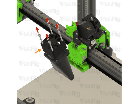
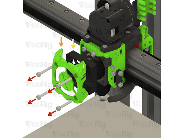
Remove the M3x25 Cap Head Screw
-
Remove the Hex Nut - M3
-
Remove the M3 Nylon Locking Hex Nut
-
Remove the M3x35 Cap Head Screw
-
Remove the 40mm_fan_duct assembly as shown
-
-
-
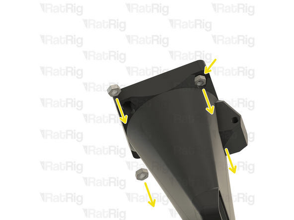
Remove the four M3x35 Cap Head Screws
-
Remove the 4028 Part Cooling Fan from the printed part, it will be re-used on the Rat Rig Toolhead V1.0
-
Remove the four Hex Nuts - M3
-
-
-
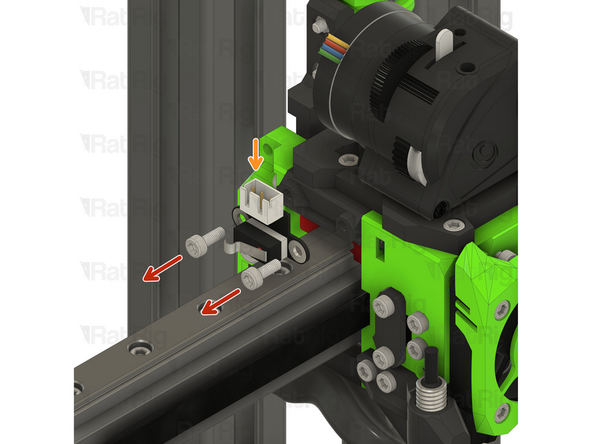
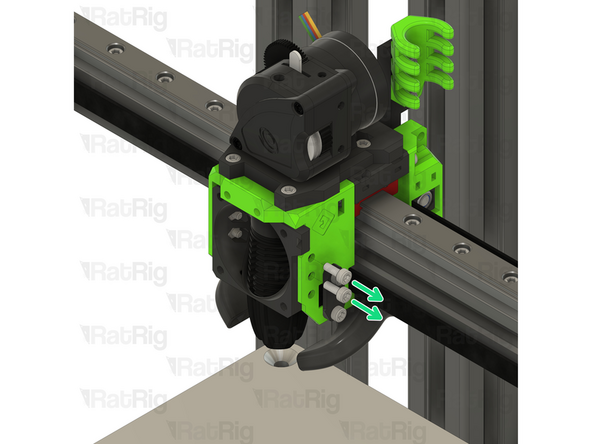
Remove the two M3x8 Cap Head Screws
-
Disconnect the Endstop Module and set it aside, it will be re-used on the Rat Rig Toolhead V1.0
-
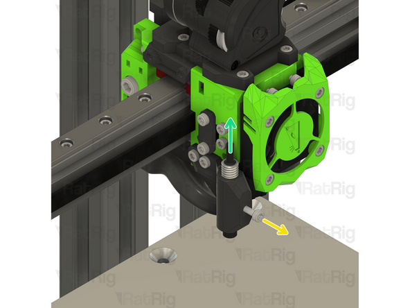
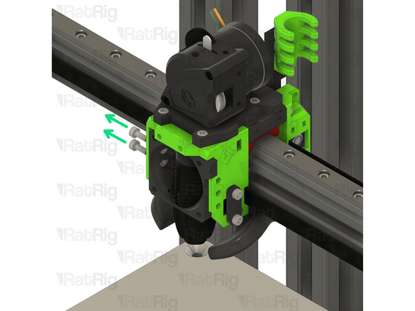
Loosen the M3x8 Cap Head Screw
-
Remove the Z-probe from the printed part, it will be re-used on the Rat Rig Toolhead V1.0
-
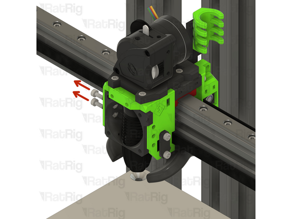
Remove the three M3x8 Cap Head Screws
-
-
-
Remove the four M3x20 Cap Head Screws
-
Remove the ratrig_eva3_shroud Printed Part
-
Remove the 4010 Axial Fan from the assembly, it will be re-used on the Rat Rig Toolhead V1.0
-
Remove the four M3x8 Cap Head Screws
-
-
-
Remove the four M3x8 Cap Head Screws
-
Gently push the hotend assembly down and away from the toolhead-
-
Rotate the hot end assembly into position as shown
-
-
-
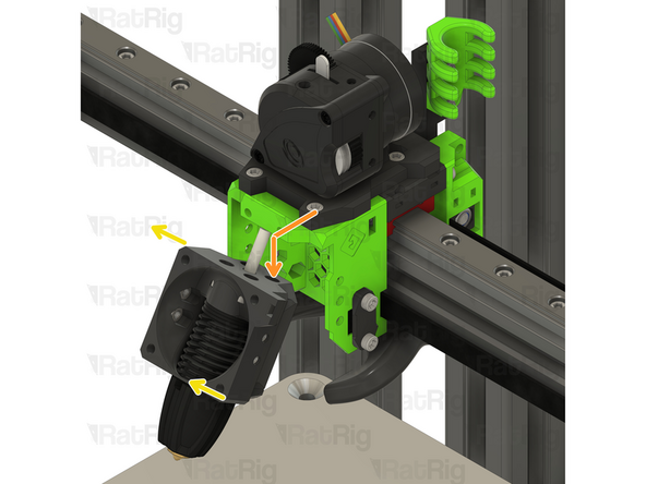
Remove the PTFE line
-
Remove the four M2.5x8 Cap Head Screws
-
Remove the Rapido hotend from the printed part, it will be re-used on the Rat Rig Toolhead V1.0
-
Tip: Insert the four M2.5x8 Cap Head Screws back in the Rapido hotend mounting points to avoid losing them.
-
-
-
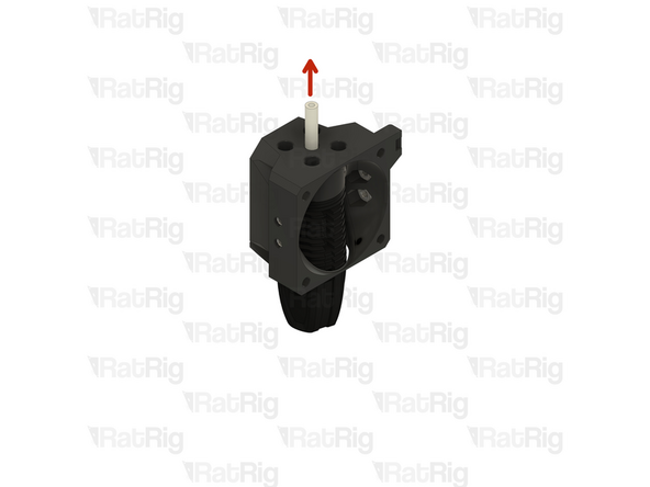
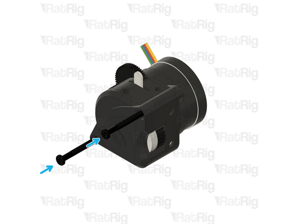
Remove the two M3x25 screws on the face of the LGX Lite which secure the motor in place
-
Remove the Bondtech LGX Lite motor from the back of the LGX Lite extruder
-
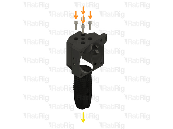
Remove the three M3x12 Cap Head Screws
-
-
-
Remove the two M3x8 Cap Head Screws
-
Remove the extruder assembly
-
The new Rat Rig toolhead uses the Orbiter V2,
-
Remove the M3x8 Cap Head Screws holding the LGX Lite to the EVA3 drive_lgx_lite Printed Part
-
Reassemble the LGX Lite so you can safely store it.
-
-
-
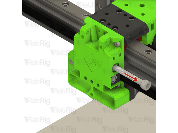
Loosen the M5x40 Cap Head Screw
-
Pull the belt to help remove the CoreXY belt grabber
-
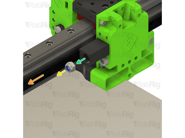
Remove the M5 nylon locking nut
-
Remove the belt grabber from the toolhead
-
Repeat the previous steps and remove the other CoreXY belt grabber
-
-
-
Remove the two M3x8 Cap Head Screws
-
Remove the belt front belt holder
-
Repeat the previous steps for the other front belt holder
-
-
-
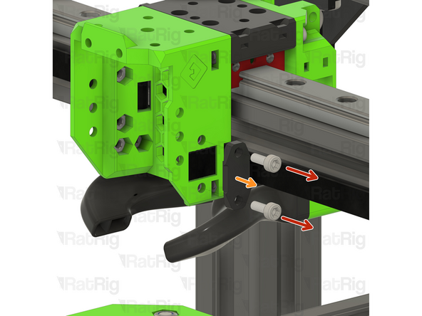
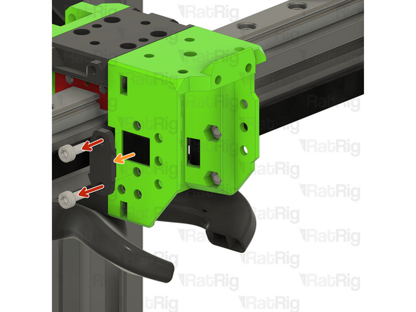
Remove the two M3x35 Cap Head Screws
-
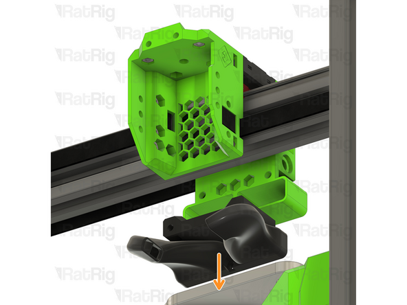
Pull down on the EVA horn ducts
-
-
-
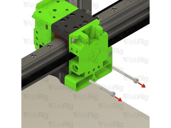
Remove the two M3x35 Cap Head Screws
-
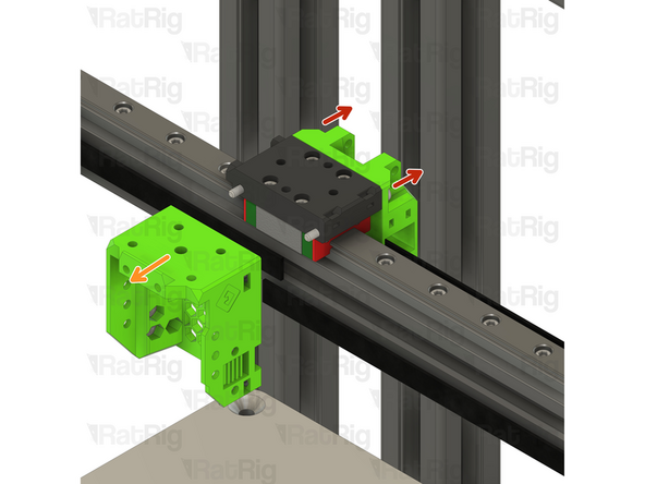
Pull on the EVA3 front assembly to remove it
-
Pull on the EVA3 back assembly to remove it
-
Remove the four M3x8 Cap Head Screws
-
Remove the EVA3 mgn12 mount
-
-
-
Some components of the V-Core 3.1 need to be upgraded to support the new Rat Rig Toolhead. The following steps will show you how.
-
-
-
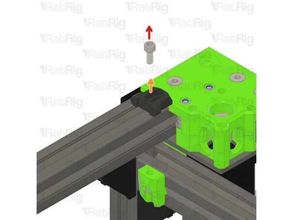
Locate the rear cable holder
-
Remove the M6x12 Cap Head Screw
-
Remove the electronics_wire_guide_rear printed part from the frame
-
Remove the M6 3030 Drop in T-nut
-
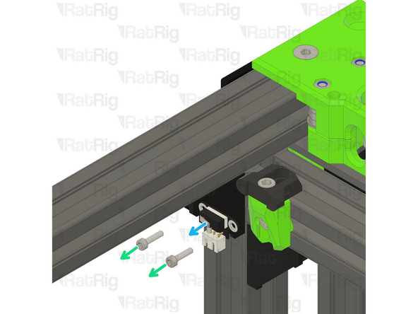
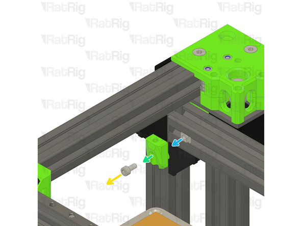
Locate the Y endstop mount
-
Remove the two M3x12 Cap Head Screws
-
Disconnect the Enstop Module and set it aside, it will be re-used on the Rat Rig Toolhead V1.0
-
-
-
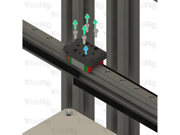
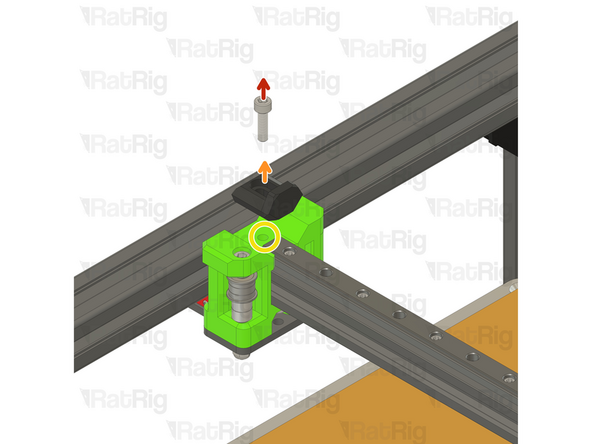
Remove the M5x12 Cap Head Screw
-
Remove the Y_max_endstop_slider printed part
-
Remove the M5x10 Cap Head Screw
-
Remove the Y endstop_max_block printed part
-
Remove the M5 3030 Drop in T-nut
-
-
-
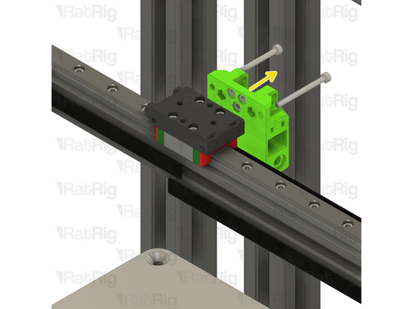
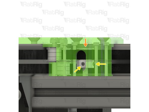
Remove the M5x18 Cap Head Screw
-
Remove the EVA3 endstop block
-
Avoid moving the machine around at this point, os the M5 Drop in T-nut doesn't slide around on the gantry extrusion.
-
-
-
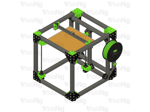
The V-Core 3.1 is now ready to receive the Rat Rig Toolhead V1.0 Upgrade kit
-
-
-
The next steps will cover the assembly of the Rat Rig toolhead V1.0 upgrade kit
-
-
-
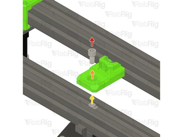
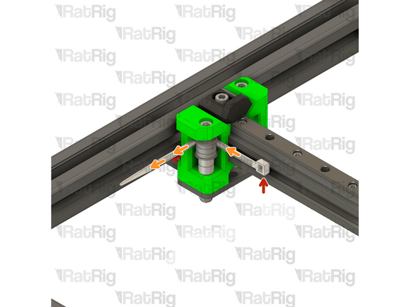
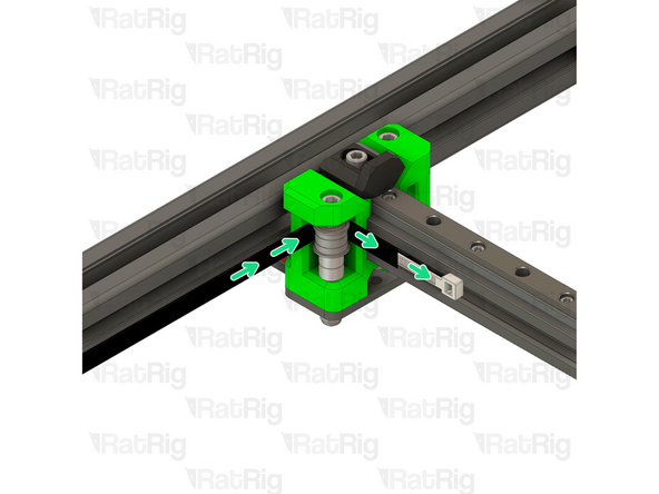
M5x18 Cap Head Screw
-
x_endstop printed part
-
Carefully insert the M5x18 Cap Head Screw into the already existing M5 Drop in T-nut
-
-
-
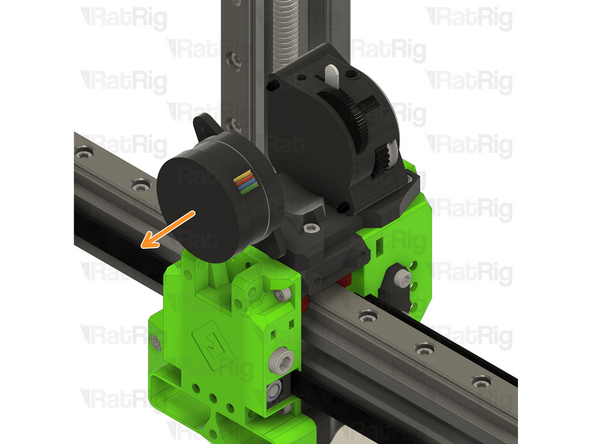
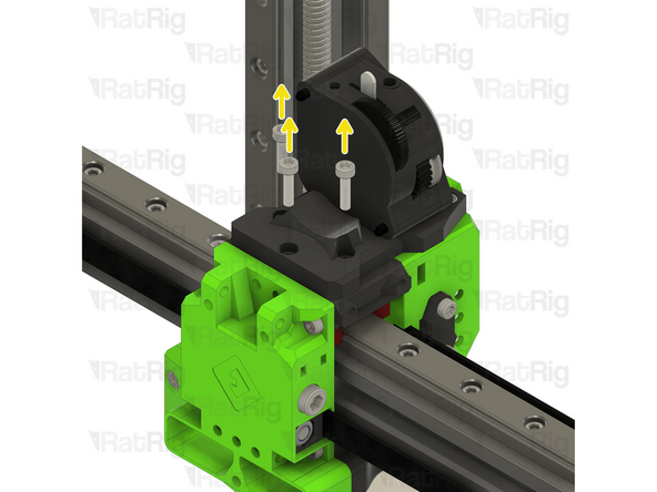
Remove the M3x45 Cap Head Screws
-
Remove the Stepper motor
-
Remove the M5x40 Cap Head Screws
-
-
-
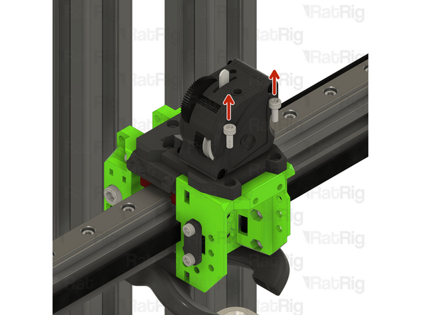
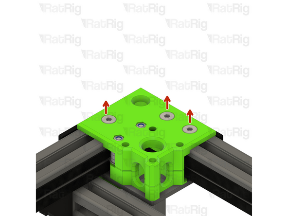
Remove the three M6x14 Screws
-
If the M6 Drop in T-nuts fall off, loosely thread them in the screws so you can easly reinstall the CoreXY motor cage top easily.
-
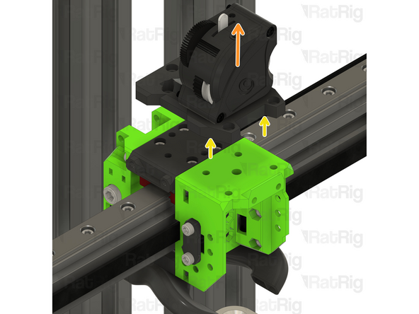
Remove the CoreXY motor cage top
-
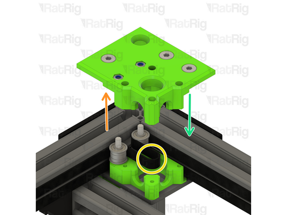
Remove both of the old belts, then insert the two new ones following the same paths
-
Reinstall the CoreXY motor cage top
-
-
-
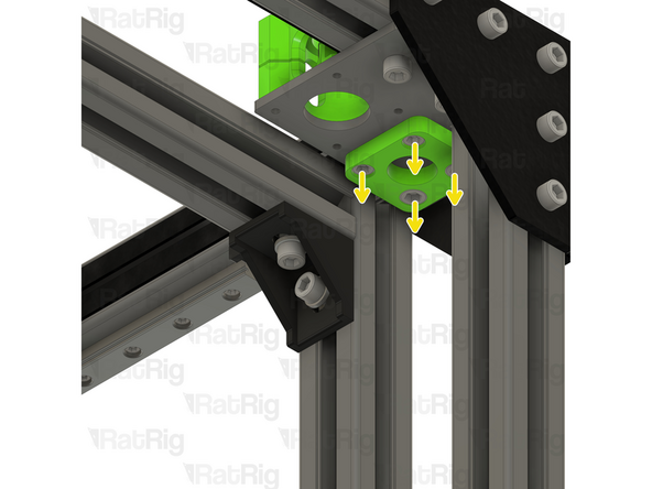
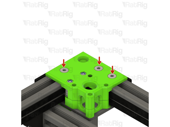
Tighten the three marked M6x14 screws to secure the CoreXY motor cage top to the frame
-
Tighten the M5x40 screws to secure the bearing stacks into the CoreXY motor cage top
-
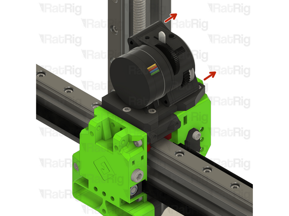
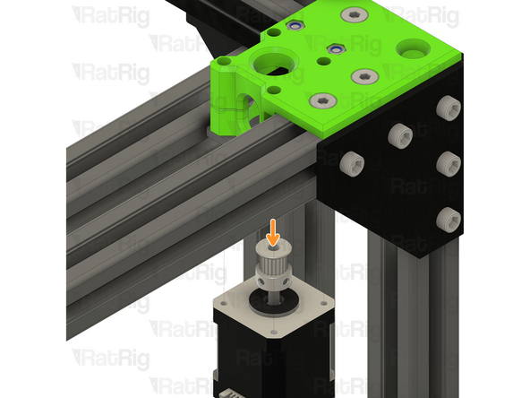
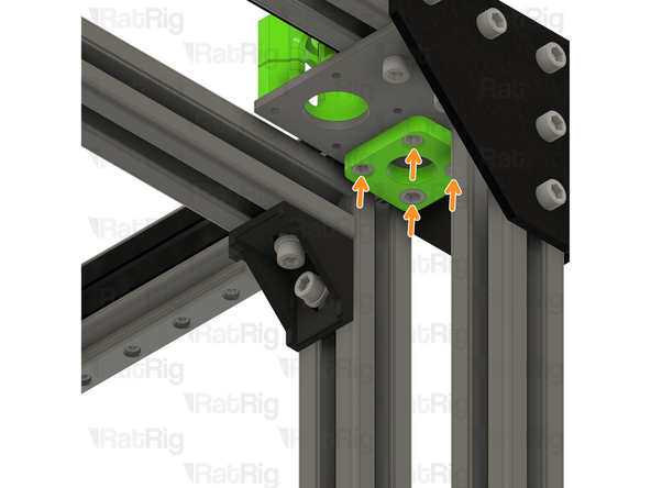
Position the NEMA17 motor up and into the motor cage from below, it will be secured in the next step
-
-
-
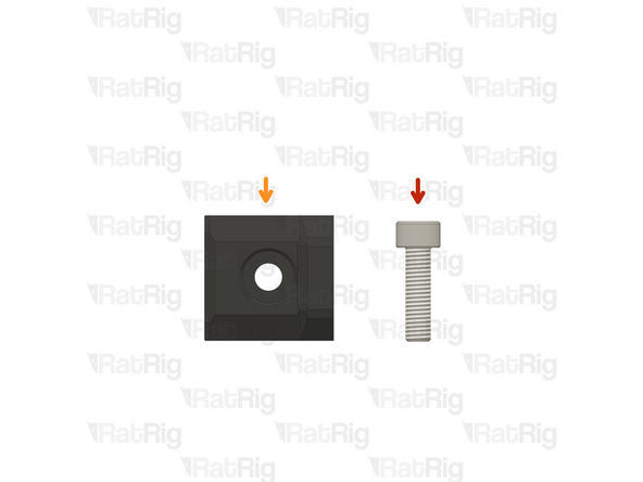
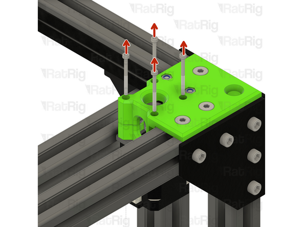
Insert the M3x35 screws into the xy_motor_cage_left_top as shown, and fasten them to secure the NEMA17 motor to the mount
-
Check the alignment of the timing pulley, the belt should be on the middle of the pulley as shown
-
Adjust the pulley up or down if required to make sure the belt is in the middle of the pulley
-
Fasten both M3 grub screws to securely mount the timing pulley to the NEMA17 motor shaft
-
Repeat Steps 21 - 24 for the other CoreXY motor mount cage.
-
-
-
This step is not mandatory, it's just a Rat Rig tip on how to feed the belts on the idlers.
-
Zip Tie
-
The wider the zip tie is, the easier the process will be
-
Bend the tip of the zip tie a little bit and feed it between the printed part and the idler, as shown
-
Insert the belt between the zip tie and the idler
-
Slowly feed the belt and pull the zip tie at the same time
-
-
-
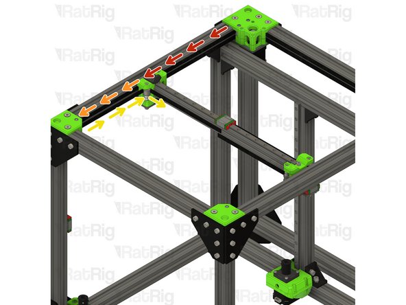
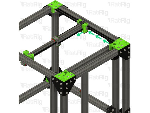
Take the loose end of the top CoreXY belt on the left hand side:
-
Feed the belt behind the left xy_joiner
-
Down and around the front xy_idler
-
Around the front bearing stack on the left xy_joiner
-
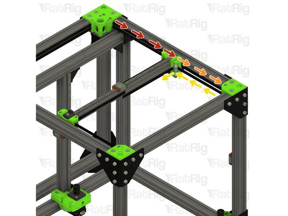
Take the loose end of the bottom CoreXY belt on the left hand side:
-
Feed the belt around the rear bearing stack on the xy_joiner
-
-
-
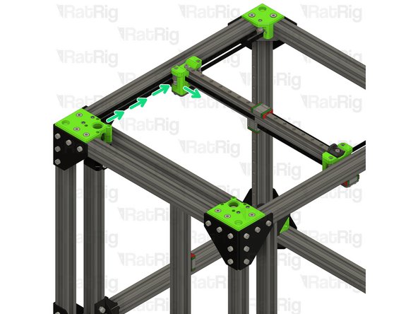
Take the loose end of the bottom CoreXY belt on the right hand side:
-
Feed the belt behind the right xy_joiner
-
Down and around the front xy_idler
-
Around the front bearing stack on the right xy_joiner
-
Take the loose end of the top CoreXY belt on the right hand side:
-
Feed the belt around the rear bearing stack on the xy_joiner
-