
Video Overview
-
-
1x 362mm 2020 Extrusion
-
1x V-Minion X-Plate
-
2x M3 Nylon Locking Hex Nut
-
3x 2020 Square T-Nut - M5
-
2x 2020 Drop-in T-Nut - M5
-
4x M3x8 Cap Head Screw
-
5x M5x10 Cap Head Screw
-
x_gantry_end_cap printed part
-
-
-
V-Minion X-Plate
-
M3x8 Cap Head Screw
-
Slide the Z-axis up and down the rail to make sure it moves smoothly
-
If the carriage binds at all, slightly loosen the M3x8 screws and check again
-
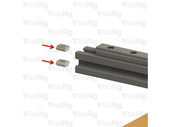
M5x10 Cap Head Screw
-
2020 Square T-Nut - M5
-
Loosely thread the 2020 square T-Nuts onto the M5x10 screws. Do not tighten them at this point
-
-
-
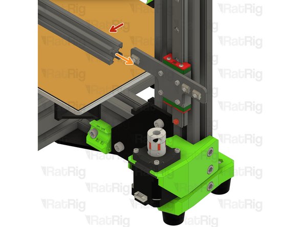
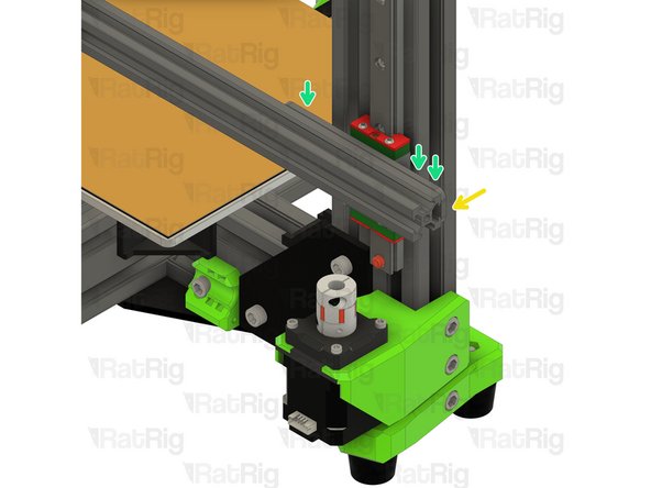
362mm 2020 Extrusion
-
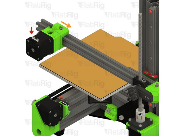
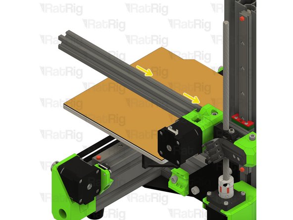
Slide the 2020 extrusion onto the 2020 square T-nuts as shown
-
Make sure that the 2020 extrusion end is flush with the side of the V-Minion X-Plate
-
Fasten the three M5x10 screws to secure the 2020 extrusion to the X-Plate
-
-
-
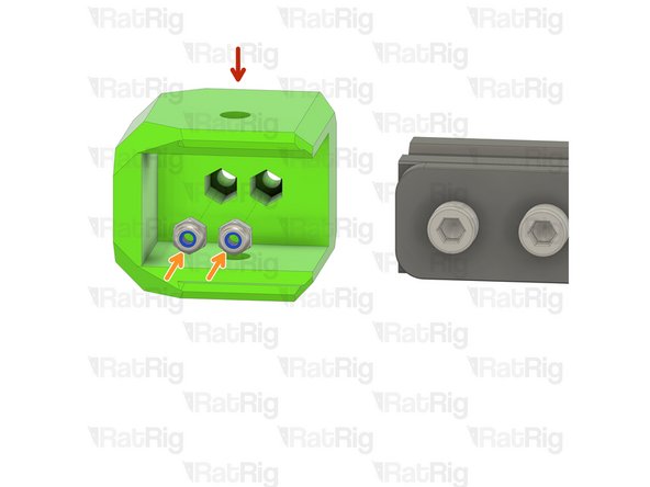
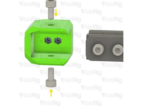
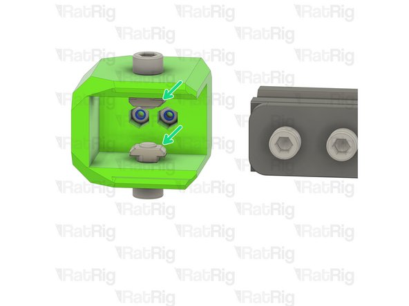
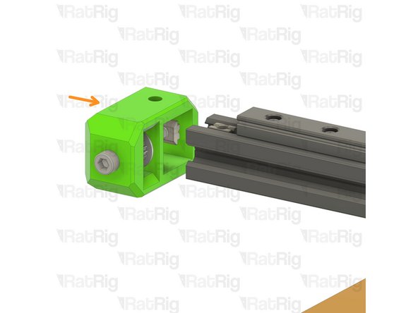
x_gantry_end_cap printed part
-
M3 Nylon Locking Hex Nut
-
Insert the M3 nylon locking nuts into the printed part as shown
-
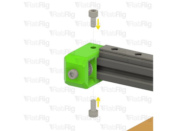
M5x10 Cap Head Screw
-
2020 Drop-in T-Nut - M5
-
Loosely thread the 2020 T-Nuts onto the M5x10 screws. Do not tighten them at this point
-
-
-
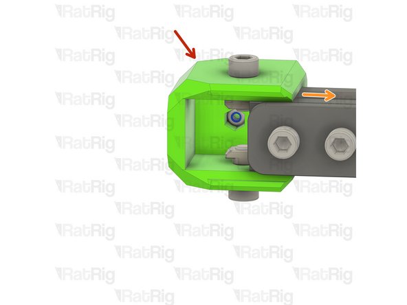
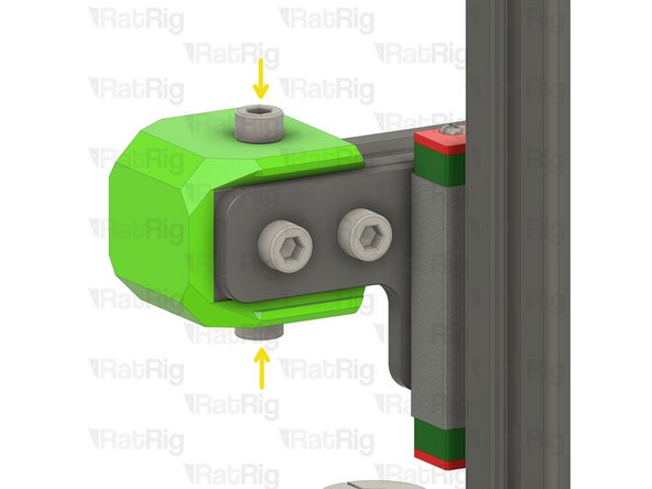
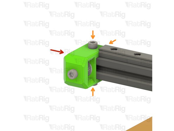
X-axis end cap assembly
-
Slide the X-axis cap onto the end of the 2020 extrusion
-
Fasten both M5x10 screws to secure the X-axis cap to the extrusion
-
Take care not to over tighten the M5x10 screws as you can damage the printed part
-
-
-
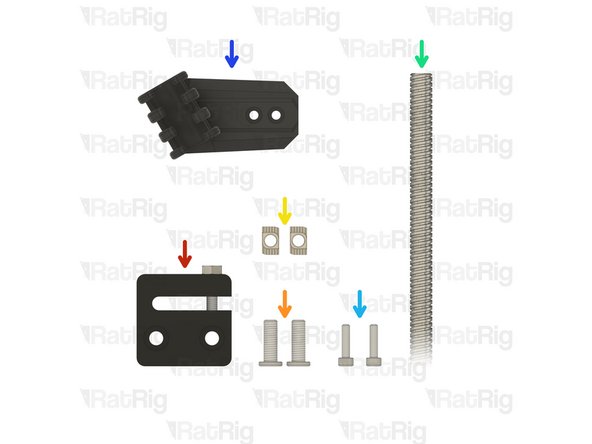
1x Anti-Backlash Nut Block
-
2x M5x15 Low Profile Cap Head Screw
-
2x 2020 Drop-in T-Nut - M5
-
1x 250mm TR8*4 Leadscrew
-
2x M3x12 Cap Head Screw
-
x_wire_holder printed part
-
-
-
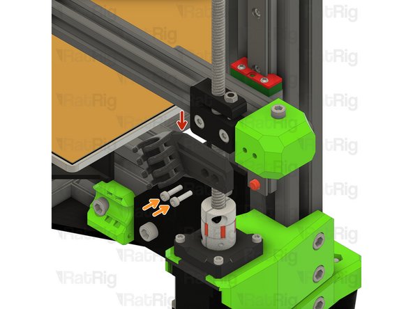
Anti-Backlash Nut Block
-
The following parts are provided with the anti-backlash nut
-
M4 Grub Screw
-
M4 Nut
-
Install the M4 grub screw into the anti-backlash nut block as shown. Stop turning the grub screw when it touches the bottom part of the nut block
-
Secure the grub screw by installing the M4 nut as shown
-
-
-
Anti-Backlash Nut Block
-
M5x15 Low Profile Cap Head Screw
-
2020 Drop-in T-Nut - M5
-
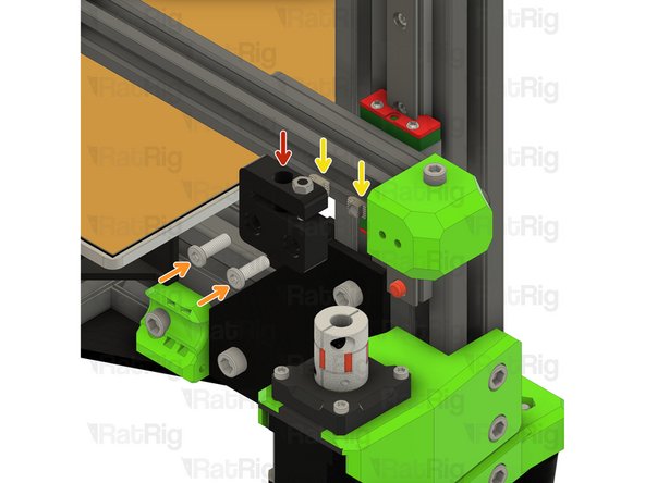
Loosely thread the 2020 T-Nuts onto the M5x15 screws. Do not tighten them at this point
-
Fit the anti-backlash nut block to the 2020 extrusion, but do not tighten the M5x15 screws fully
-
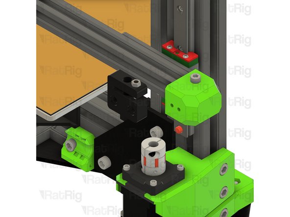
Thread the leadscrew through the anti-backlash nut block...
-
...and into the Z-axis spider coupler
-
Do not fasten the M5x15 screws, or the M3 screw on the spider coupler yet. We will do so after aligning everything in the next step
-
-
-
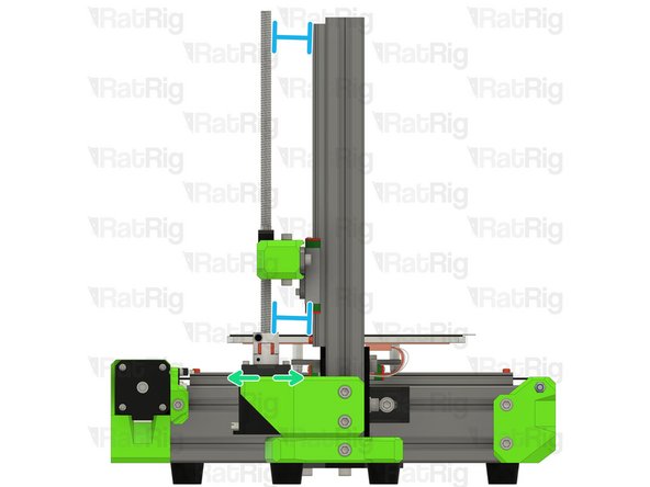
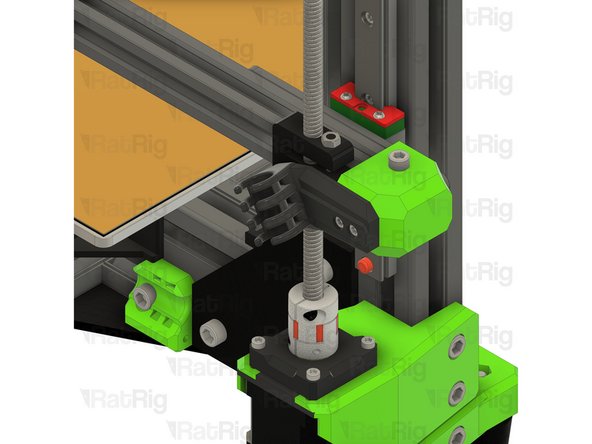
Begin by loosening the four M3x18 screws on the Z-axis stepper motor
-
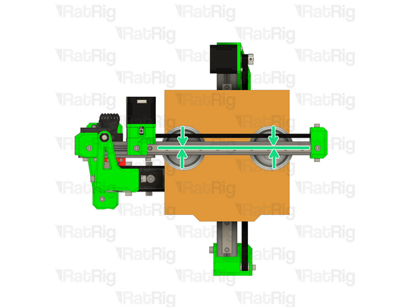
To align the leadscrew, look at the V-Minion from above, as pictured:
-
Adjust the position of the anti-backlash nut left or right until the leadscrew is in-line with the Z-axis stepper motor
-
Secure the two M5x15 screws when this is achieved
-
Adjust the position of the Z-axis motor forwards and backwards until the leadscrew is parallel with the frame
-
Secure the four M3x18 screws when this is achieved
-
Take care not to over tighten the M3x18 screws as you can damage the printed parts
-
Fasten the M3 screw on the spider coupler to secure the leadscrew
-
-
-
x_wire_holder printed part
-
M3x12 Cap Head Screw
-
Fasten the x_wire_holder to the X-axis using the M3x12 screws
-
Take care not to over tighten the M3x12 screws as you can damage the printed parts
-
-
-
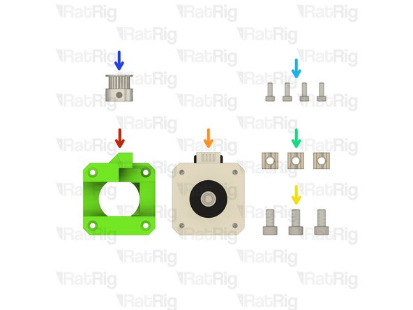
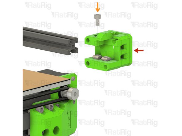
x_motor_cage printed part
-
1x 40mm NEMA17 Stepper Motor
-
3x M5x10 Cap Head Screw
-
3x 2020 Square T-Nut - M5
-
4x M3x8 Cap Head Screw
-
1x 20 Tooth 2GT Timing Pulley for 6mm Belt
-
-
-
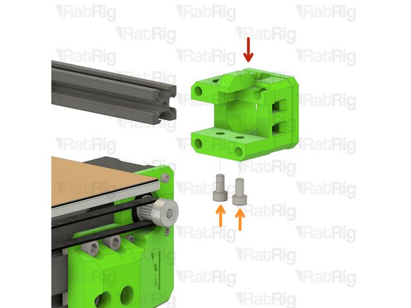
x_motor_cage printed part
-
M5x10 Cap Head Screw
-
2020 Square T-Nut - M5
-
Loosely thread the 2020 T-Nuts onto the M5x10 screws. Do not tighten them at this point
-
-
-
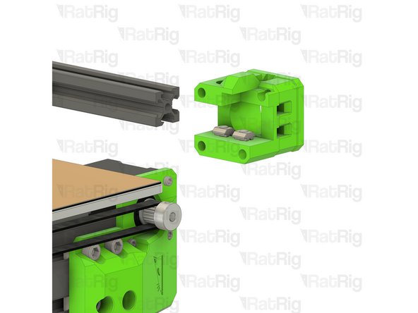
x_motor_cage printed part
-
M5x10 Cap Head Screw
-
2020 Square T-Nut - M5
-
Loosely thread the 2020 T-Nut onto the M5x10 screw. Do not tighten it at this point
-
-
-
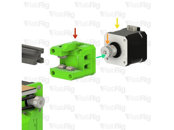
Assembly from Step 12
-
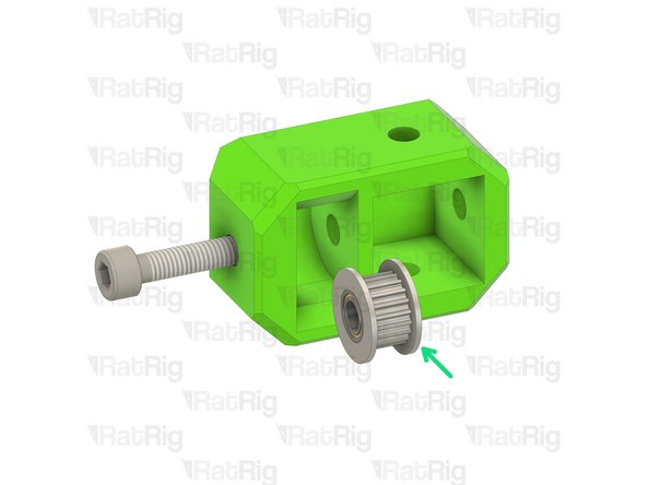
20 Tooth 2GT Timing Pulley for 6mm Belt
-
40mm NEMA17 Stepper Motor
-
Position the timing pulley as shown. Do not fully tighten the grub screws yet as the alignment will need to be adjusted later
-
Insert the stepper motor into the mount as shown
-
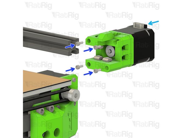
M3x8 Cap Head Screw
-
Fasten the stepper motor to the mount using the M3x8 screws
-
Take care not to over tighten the M3x8 screws as you can damage the printed parts
-
-
-
X-axis motor assembly from Step 13
-
Install the X-axis motor assembly onto the 2020 extrusion as shown
-
Push the assembly all the way along the X-axis for the moment
-
Do not fasten the M5x10 screws yet, this will be done later
-
-
-
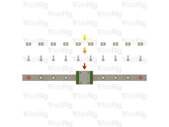
1x 250mm MGN12 Linear Rail
-
10x M3x8 Cap Head Screw
-
10x 2020 Drop-in T-Nut - M3
-
Please refer to the Rat Rig Linear Rail Guide (Steps 1 & 2) for full details on preparing the rails before installation.
-
The linear rail carriages are not interchangeable. Do not try to use a carriage on a different linear rail than the one it was supplied with.
-
-
-
Frame assembly from Step 14
-
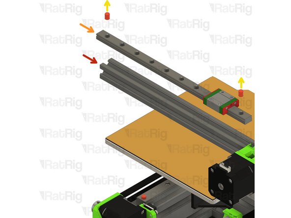
MGN12 Linear Rail
-
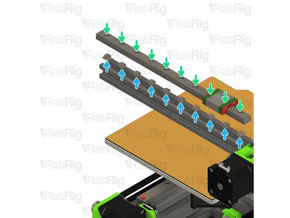
Remove the plastic stops installed in the ends of the linear rail
-
Do not allow the linear rail carriage to leave the end of the rail.
-
Insert an M3x8 screw in each of the holes on the linear rail
-
Loosely thread a 2020 T-Nut onto each of the M3x8 screws
-
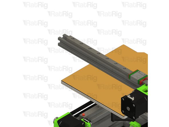
Slot the assembled linear rail into the X-axis 2020 extrusion, do not fasten any of the M3x8 screws yet
-
-
-
x_idler printed part
-
1x M5x25 Cap Head Screw
-
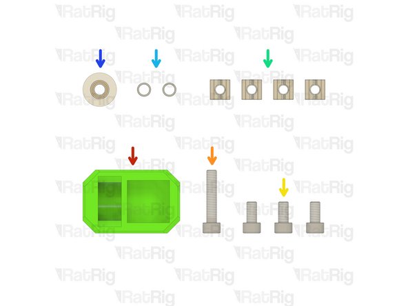
3x M5x10 Cap Head Screw
-
4x 2020 Square T-Nut - M5
-
2x Micro Precision Shim
-
1x 20 Tooth 2GT Idler Pulley for 6mm Belt
-
-
-
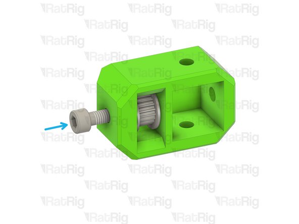
x_idler printed part
-
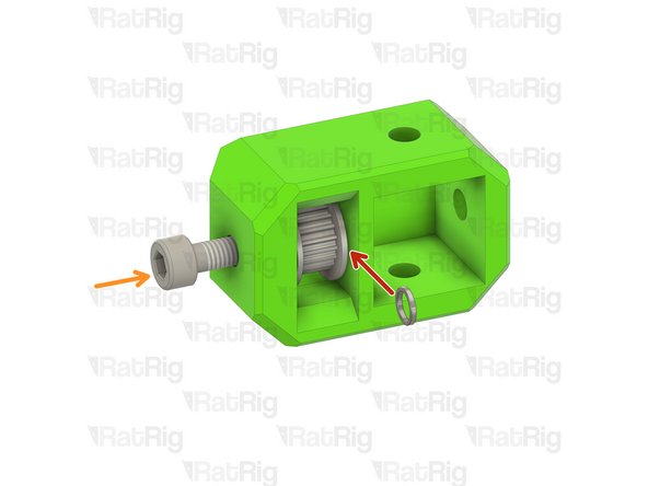
M5x25 Cap Head Screw
-
Install one precision micro shim onto the M5x25 screw
-
Install the toothed 2GT idler onto the M5x25 screw
-
Insert the M5x25 cap head screw further in preparation for the next step
-
-
-
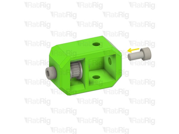
Similar to the Y-axis idler assembly, install the second precision micro shim onto the M5x25 screw
-
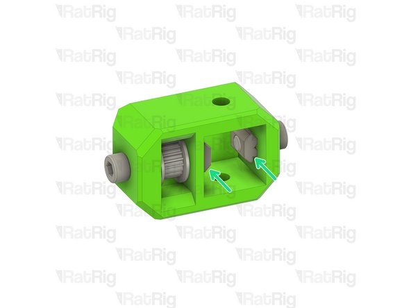
The assembly should have a micro precision shim on either side of the toothed idler
-
Fully insert the M5x25 as shown
-
M5x10 Cap Head Screw
-
2020 Square T-Nut - M5
-
Loosely thread the 2020 T-Nuts onto the M5 screws. Do not tighten them at this point
-
-
-
2020 Square T-Nut - M5
-
Insert one 2020 T-nut into the top of the 2020 X-axis extrusion as shown...
-
... and one into the underside of the extrusion
-
Install the X-axis idler onto the end of the 2020 X-axis extrusion
-
M5x10 Cap Head Screw
-
Insert one M5x10 screw in both the top and bottom of the X-axis idler, loosely fastening them into the 2020 T-nuts in the extrusion
-
-
-
Make sure the 2020 extrusion is fully inserted into the X-axis idler
-
Fasten all three M5x10 screws
-
Take care not to over tighten the M5x10 screws as you can damage the printed part
-
Fasten the M5x25 screw
-
Check that the toothed idler rotates without binding. If the idler is difficult to rotate, loosen the M5x25 screw until the idler rotates smoothly
-
Take care not to over tighten the M5x25 screw as you can damage the printed part
-
-
-
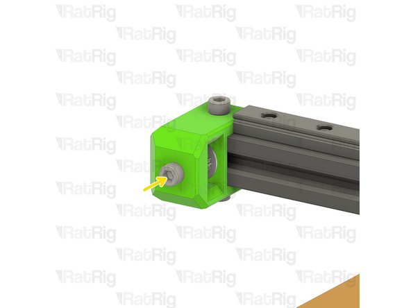
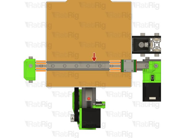
MGN12 Linear Rail
-
Make sure the linear rail is centred on the 2020 extrusion
-
The measurement between the linear rail and the side of the 2020 extrusion should be 4mm at all points
-
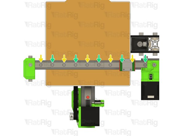
Fasten the M3x8 screws, starting from the left side
-
Double check the position of the linear rail
-
Fasten the remaining M3x8 screws, starting from the left side
-
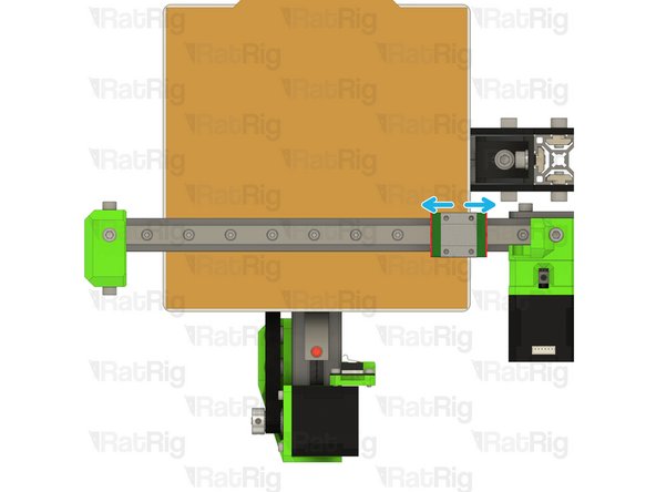
Check that the carriage runs smoothly along the length of the rail
-
-
-
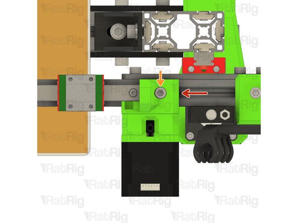
Push the X-axis motor as shown, it should be flush with the end of the linear rail
-
Fasten the marked M5x10 screw
-
Fasten the two marked M5x10 screws to fully secure the X-axis motor into place
-
Take care not to over tighten the M5x10 screws as you can damage the printed part
-
-
-
1x M6x12 Cap Head Screw
-
1x 3030 Drop-in T-Nut - M6
-
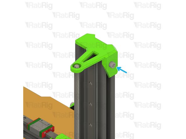
z_cap printed part
-
-
-
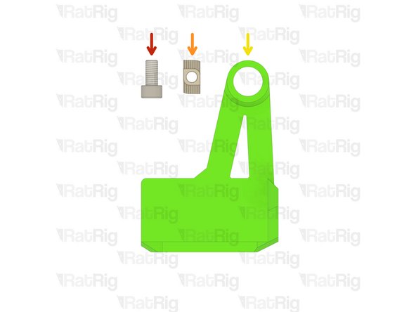
z_cap printed part
-
M6x12 Cap Head Screw
-
3030 Drop-in T-Nut - M6
-
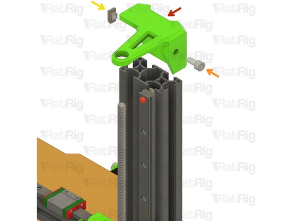
Loosely thread the 3030 T-Nut onto the M6x12 screw. Do not tighten it at this point
-
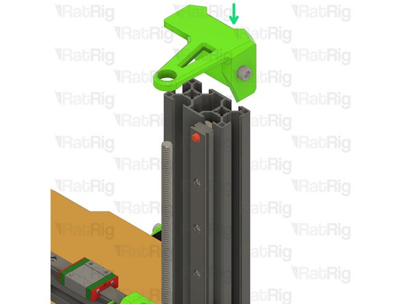
Install the z_cap as shown
-
Fasten the M6x12 screw to secure the cap to the V-Minion frame
-
Take care not to over tighten the M6x12 screw as you can damage the printed part
-
-
-
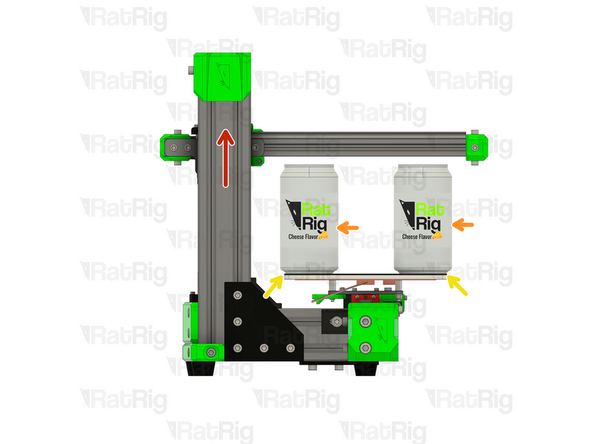
Rotate the lead screw to lift the X-axis
-
Place two soda cans on top of the bed
-
Use two soda cans of the same brand if possible. Soda cans have very good dimension tolerances due to shipping and brand refill, this makes them a easy to source precise tool.
-
Make sure the Cans are fully seated on the bed
-
Place the Cans on the middle of the X-axis
-
Lossen the screws on the X-gantry plate
-
Cans are not included in the Rat Rig Kit!
-
-
-
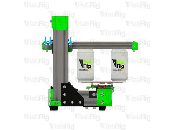
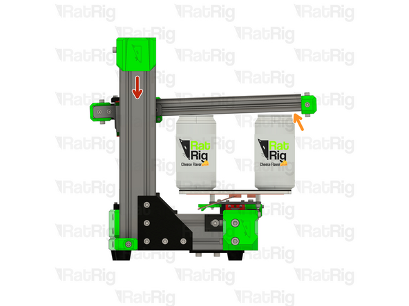
Rotate the lead screw to lower the X-axis
-
If the X-axis is lowered too far, the gap on the right soda can will increase
-
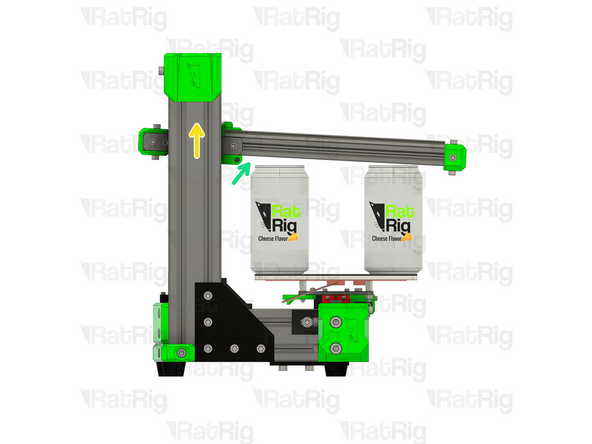
Rotate the lead screw to lift the X-axis
-
If the X-axis is lifted too much, the gap on the left soda can will increase
-
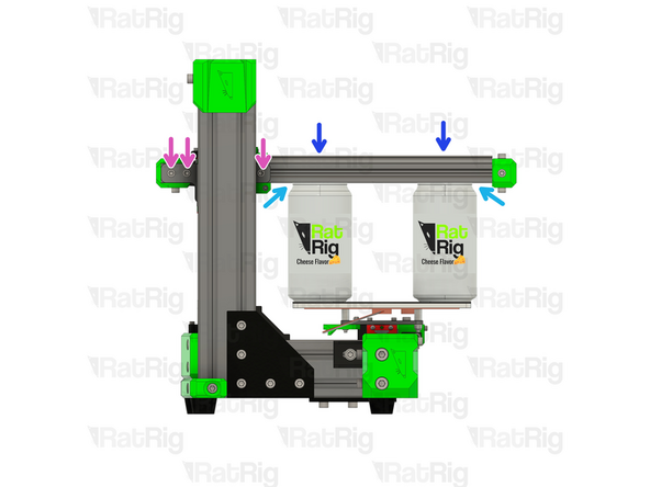
Adjust the height of the X-axis until the gap on both soda cans is the same
-
Push the X-axis down with 2 fingers to really make sure the extrusion sits flush with the cans.
-
Re-tighten the screws on the X-gantry plate, making sure the gap on both soda cans remains the same
-


Cancel: I did not complete this guide.
21 other people completed this guide.