-
-
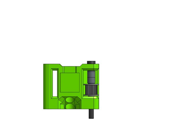
The focus of this guide is the X gantry which requires 2 printed parts which you can identify with the letters on the back:
-
R for right (looking from the front of the printer)
-
L for left
-
Take note of the difference between the shim types:
-
Micro
-
Mini
-
Spacer
-
-
-
You will use the micro shims only on the top and bottom of the toothed idlers. All other shims are the mini shims.
-
The toothed idlers are on the front and the smooth idlers are on the back of the XY Joiners.
-
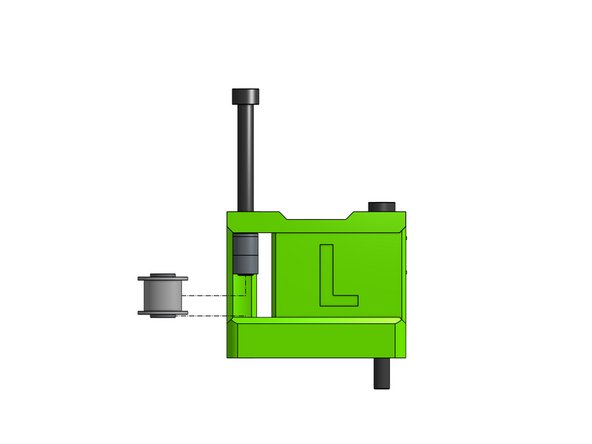
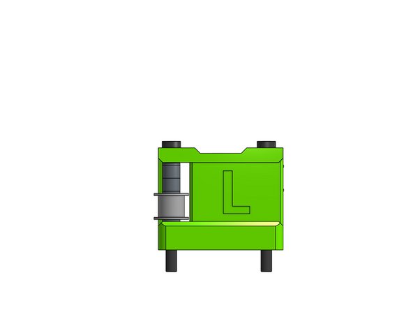
The left XY Joiner has its toothed idler on top of the stack and the smooth one in the bottom.
-
It's the other way around for the right XY joiner - toothed idler in the bottom and the smooth one on top of the stack.
-
The tolerances on the XY Joiner parts are minimal and that's by design.
-
-
-
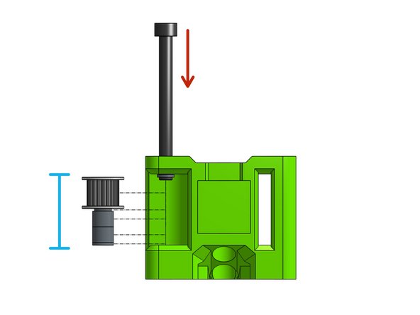
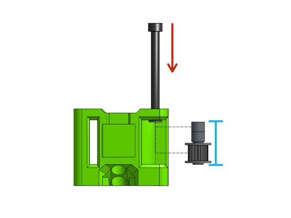
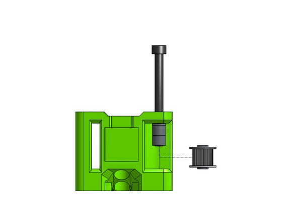
Insert the left toothed stack on the Cap Head Screw M5 x 55
-
Step by step insert the screw while adding the stack parts onto it: micro shim, toothed idler, micro shim, 2x 6mm spacers, mini shim
-
-
-
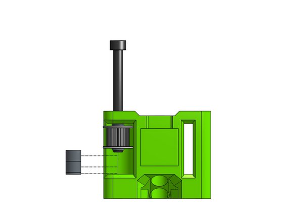
Insert the left smooth stack on the Cap Head Screw M5 x 55
-
Step by step insert the screw while adding the stack parts onto it: mini shim, 2x 6mm spacers, mini shim, smooth idler, mini shim
-
-
-
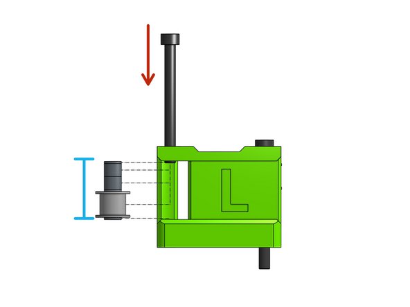
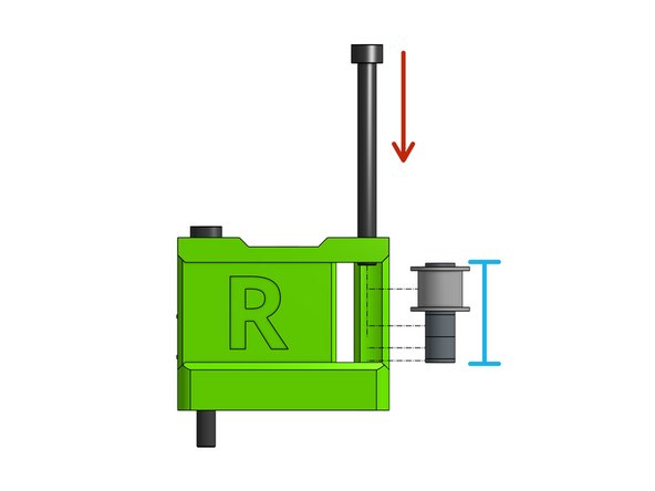
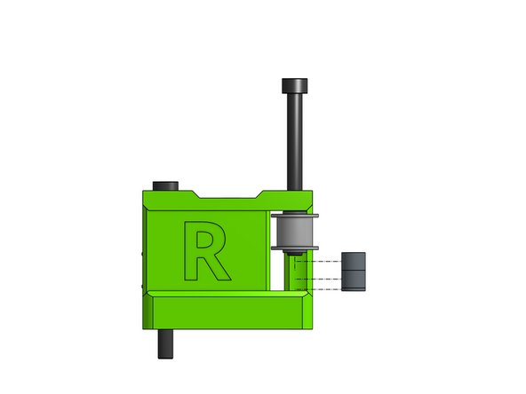
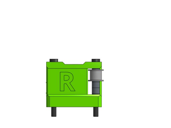
Insert the right toothed stack on the Cap Head Screw M5 x 55
-
Step by step insert the screw while adding the stack parts onto it: mini shim, 2x 6mm spacers, micro shim, toothed idler, micro shim
-
-
-
Insert the right smooth stack on the Cap Head Screw M5 x 55
-
Step by step insert the screw while adding the stack parts onto it: mini shim, smooth idler, mini shim, 2x 6mm spacers, mini shim
-
-
-
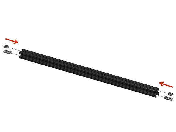
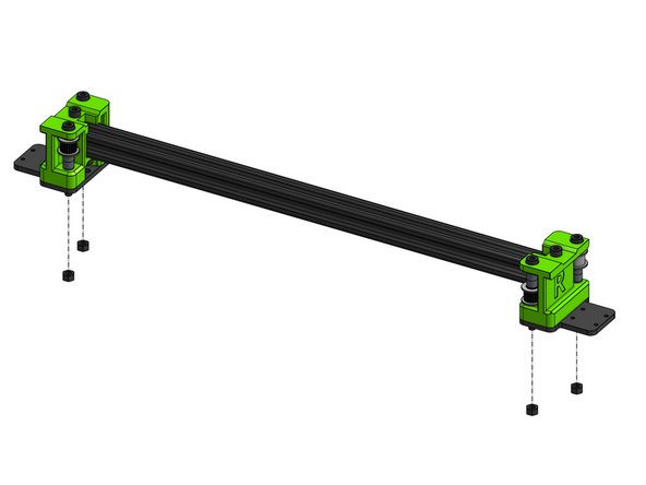
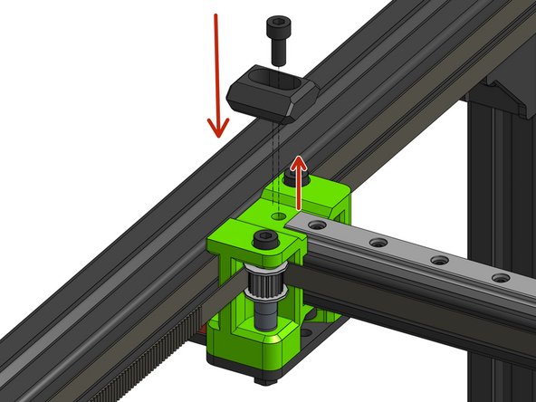
Slide the square nuts into the 2020 extrusion: 4 in the bottom slot and 2 in the top.
-
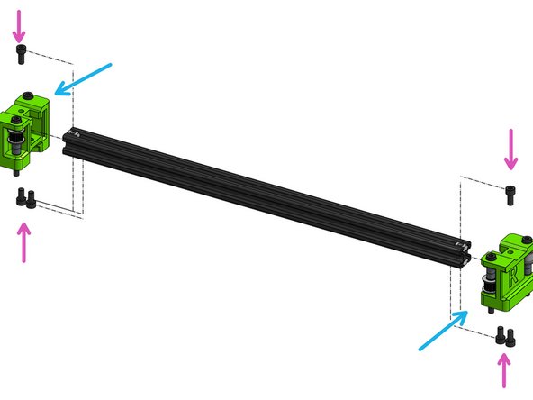
Slide the XY joiners on the 2020 exrusion
-
Watch out not to pinch your fingers!
-
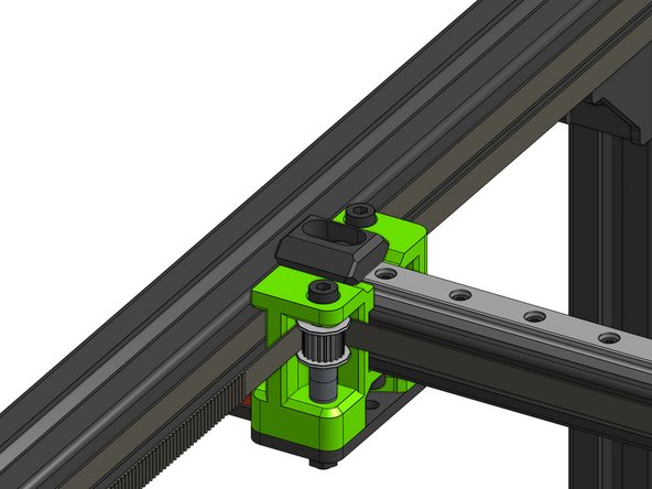
Fasten everything together with 4x Cap Head Screws M5x10 from the bottom and 2x Cap Head Screws M5 12 from the top, those bolts need to firmly grab the square nuts that are in the profile
-
-
-
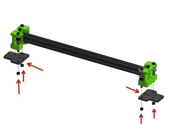
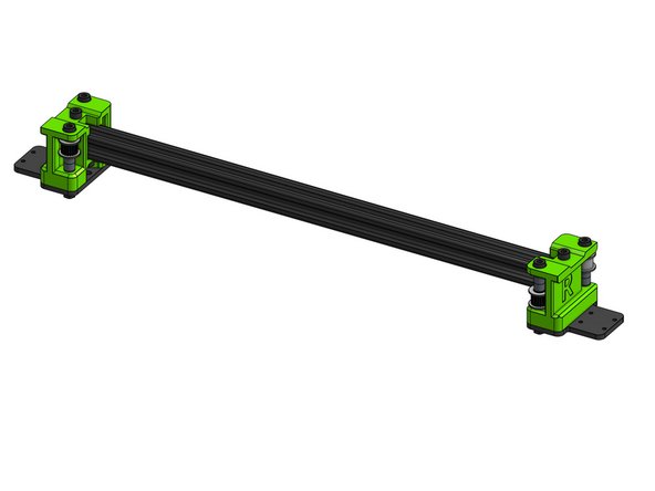
Slide the two XY plates on the M5 screws and bolt them down with M5 nuts
-
Do not over tighten or you will be compressing the bearings.
-
-
-
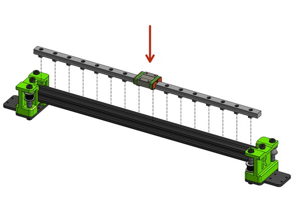
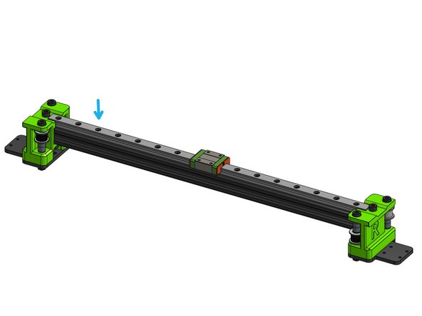
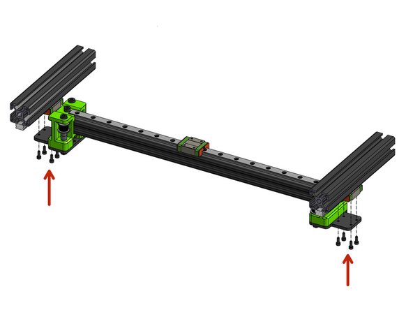
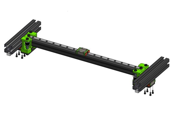
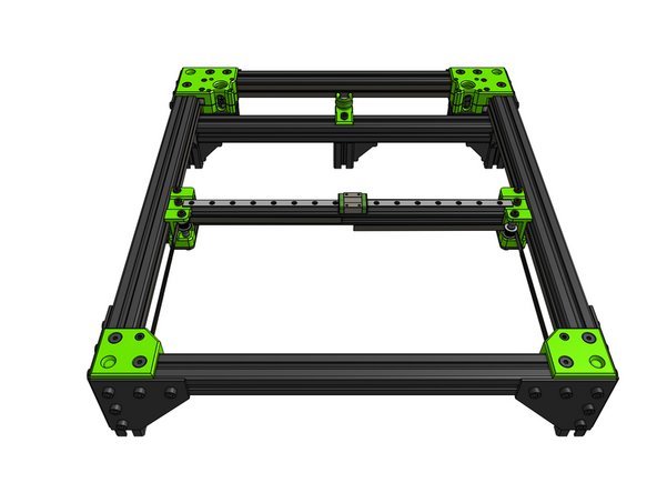
Attach the prepared MGN rail to the 2020 extrusion
-
Before Make sure to fasten all cap head screws
-
Please refer to the linear rail installation guide for instructions on the correct order to fasten the cap head screws
-
-
-
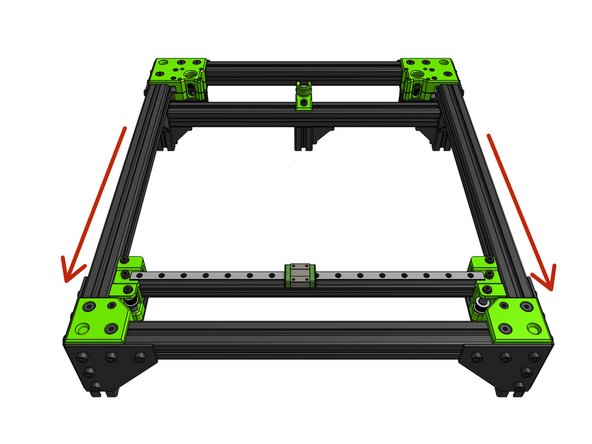
You may need to loosen the Y MGN rails for the rail to fit
-
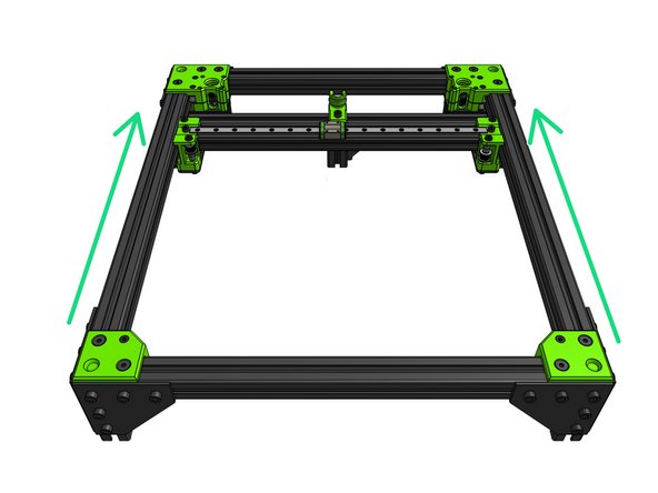
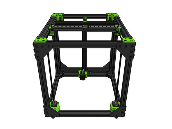
Attach the X gantry to the frame with 8x Cap Head Screws M3x8. Do not tighten those fully yet.
-
-
-
This step assumed you left the Y MGN rails screws loose
-
Move the X gantry to the front of the frame and back to uncover the first hole in the rail
-
Fully fasten in the first Y MGN screws locking their position in the X dimension of the printer while at Ymin
-
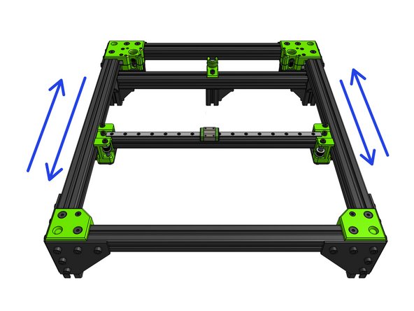
Move the gantry to the back and fully fasten the last screws of the Y MGN rails locking the rails position in the "X of the printer" at Ymax
-
Lock the 8x screws holding the X gantry to it's MGN carriages
-
Move the X gantry back and forward a few times to ensure there are no spots where the gantry moves less freely. If the gantry gets caught somewhere loosen the MGN rails and repeat the process
-
Fully fasten all of the Y MGN screws and check again if the gantry is not binding
-
-
-
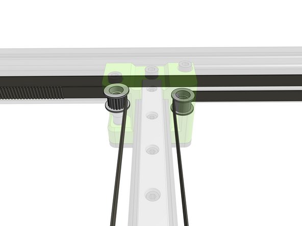
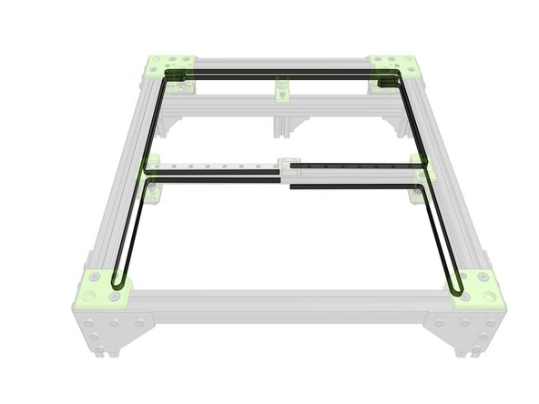
Fold the belts through the XY joiners so that all 4 ends end up in the middle of the X gantry.
-
Don't try to cut the belts to length yet!
-
-
-
Loosen the Cap Head Screw M5x12 and fasten it back through the X endstop block part
-
-
-
This guide does not include the assembly of an EVA carriage - your chosen EVA variant can be assembled last
-