
-
-
Be careful when dealing with the magnets. If you are not careful and those snap back together, you'll most likely end up with a broken magnet.
-
-
-
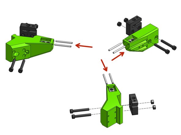
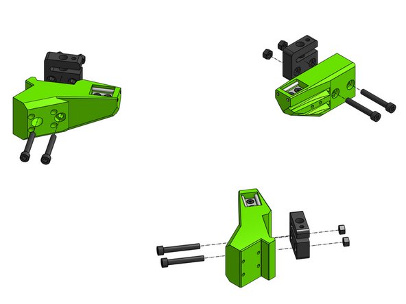
Most of the steps repeat for all of the arms, others are repeated for the front arms and there's a special step for the back arm
-
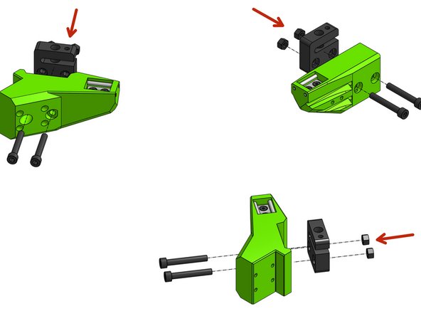
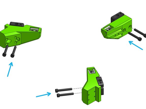
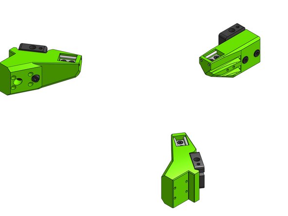
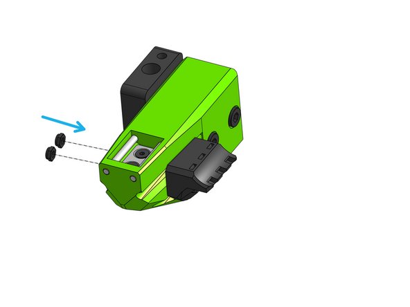
Fit the magnets in the bed arms and drop the Countersink Screws M3x20 through the magnets and printed parts
-
Fasten the magnets by attaching 2x M3 hex nuts from the bottom of each arm
-
-
-
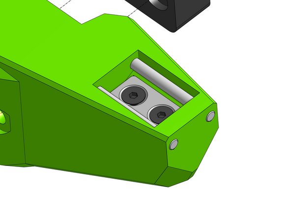
Each bed_arm takes 2 3mm x 35mm dowels. Gently press or twist the dowels into the holes.
-
Be careful not to crack the part!
-
There are many easy ways to do this safely - using force is not one of them. "Screwing" those in as one would a screw is a good practice, you can even use a drill on low RPM to push them in.
-
-
-
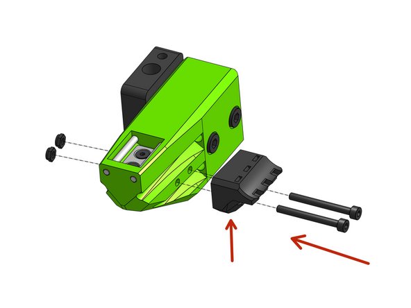
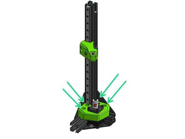
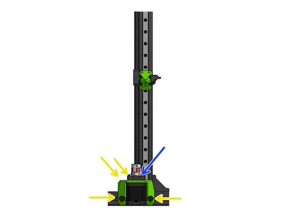
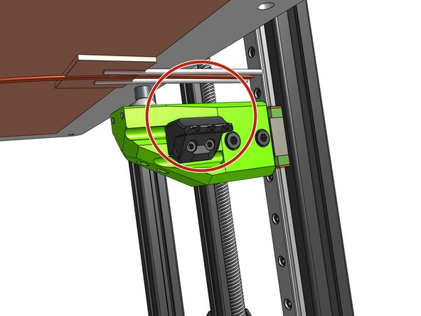
Put the M5 hex nuts into the blocks
-
Fasten the blocks by threading Cap Head Screws M5x35 through the plastic parts
-
Make sure those are secure and not moving but ensure there is no pressure from the screw tension on the blocks - those are made of a soft plastic, that when squished will bind the lead screw
-
-
-
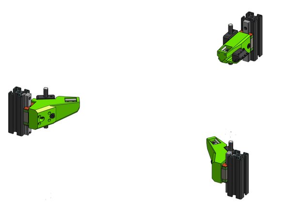
Thread each arm on its respective lead screw (loosening the lead screw in it's coupler might help here)
-
Attach the arms to the MGN carriages with 4x Cap Head Screws M3x20 for each arm
-
-
-
Thread the Cap Head Screws M3x30 through the bed_cable_relef part and attach it to the arm part
-
Insert the M3 hex nuts in the slots on the other side and pull them in by screwing in the screws - this will ensure those are aligned properly and not bind in the part.
-
-
-
The goal here is to ensure the lead screws are paralel to their rails. This step is very important to ensure proper print quality. The Z motor mounts were designed to allow some adjustment - we'll take advantage of that here
-
If needed loosen the 4 screws holding the front motor mounts and move the motor around to achieve proper lead screw alignment
-
Proper alignment is when the arm does not bind in any point
-
Ensure the alignment of the back lead screw by allowing the mount to move in X with the M5 screws
-
Alignment in Y of the back lead can be achieved by loosening of the M3 screws holding the motor to the mount
-
If you did not already, at this point make sure to fasten all screws in the MGN rails
-
Please refer to the linear rail installation guide for instructions on the correct order to fasten the cap head screws
-
-
-
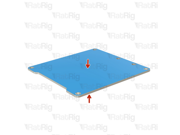
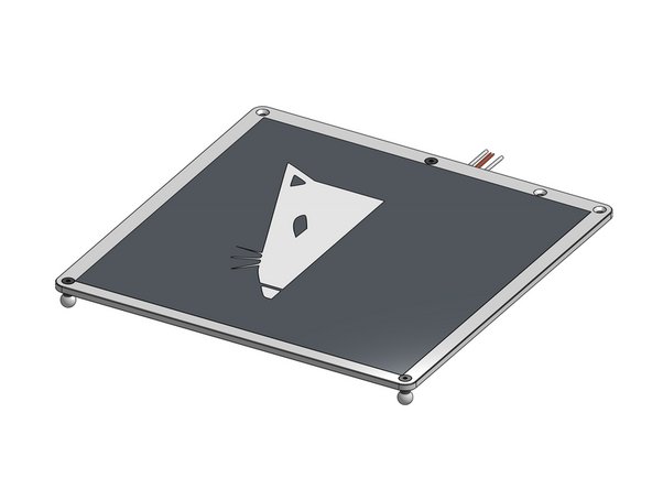
To prevent scratches, the bed plate is shipped with a protective film on both sides.
-
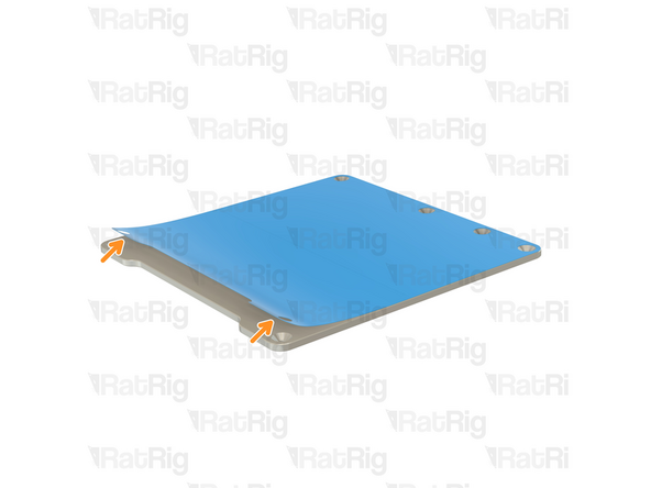
Gently peel off the protective film.
-
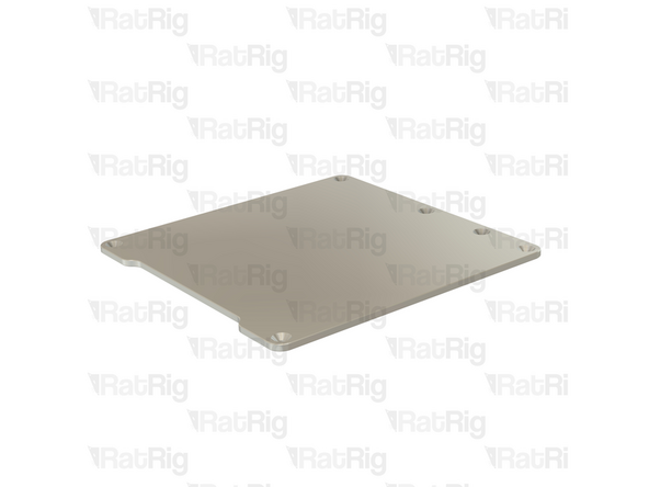
Repeat for the other side.
-
-
-
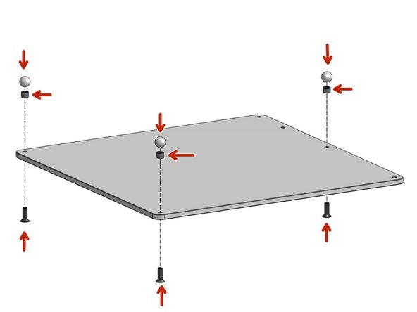
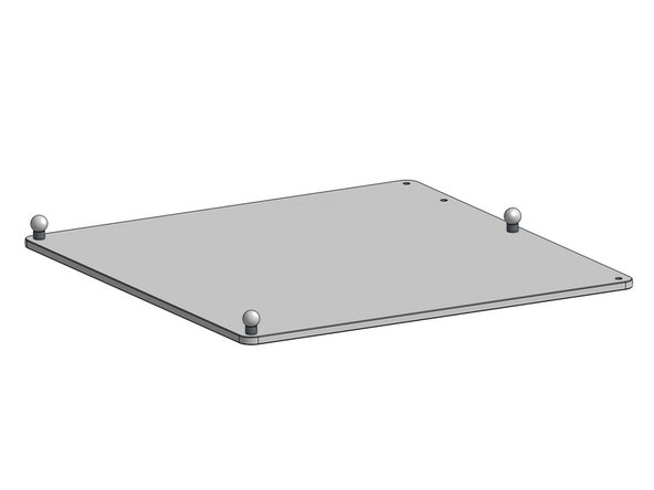
Attach the Countersink M5x16 screws to the 12mm balls through the 6mm spacers
-
-
-
This is a mains voltage element, you should consult an electrician when dealing with it
-
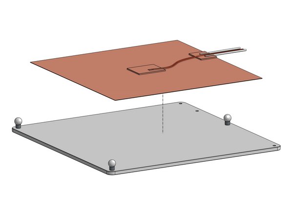
You may want to wipe the surface of the bed with >90% alcohol to make sure you are attaching to a clean surface
-
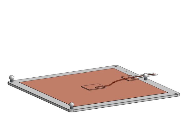
Peel off the sticker's protective layer from the pad and glue it to the bottom of the bed plate
-
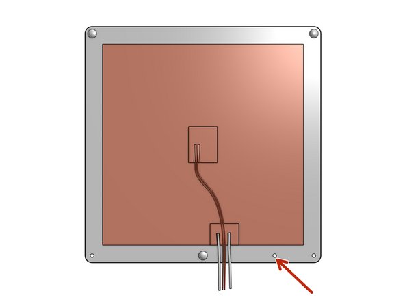
The extra hole is there for a ground wire
-
-
-
This step depends on the print surface type of your choosing but in general it's always a good idea to clean the surface from any dirt and grease
-
Attach the print surface
-
-
-
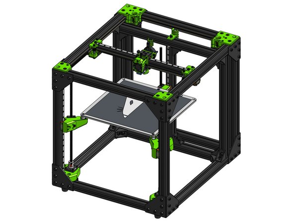
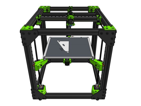
Place the assembled bed on the bed arms
-
Secure the bed wires to the bed_cable_relief part with zip ties
-
Those wires carry mains voltage, you should consult an electrician when handling them
-


Cancel: I did not complete this guide.
52 other people completed this guide.

6 Comments
There appear to be some proprietary parts. Any way you folks would consider selling say the bed, magnets, and balls? I'd love to add this set up to my custom printer.
Derrick James - Resolved on Release Reply
The bed is just a standard aluminum tooling plate. They are pretty inexpensive, and available pretty much any place in the world that has industry. Just search the internet for “cast aluminum tooling plate.” Mic6 is the tradename for the Alcoa version (this is the industry standard, buy this if you do not trust yourself to buy something different), but any plate from a reputable supplier will probably be just as good provided it is advertised as being stable. The balls are just threaded steel balls, nothing special, same for the magnets.