
Video Overview
-
-
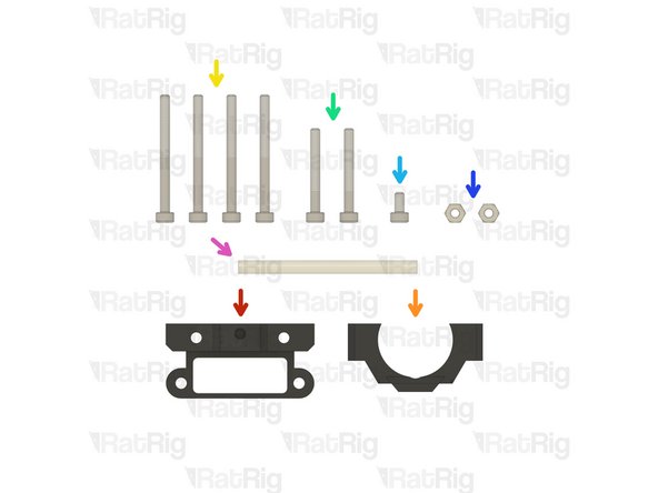
universal_face & back_cartesian printed parts
-
cartesian_cable_fin printed part
-
13x M3 Hex Nut
-
2x M3x30 Cap Head Screw
-
1x M3x25 Cap Head Screw
-
1x M3x12 Cap Head Screw
-
600mm 2GT 6mm Wide Timing Belt
-
1x 24v 5015 Blower Fan
-
-
-
universal_face printed part
-
M3 Hex Nut
-
Install an M3 hex nut into each of the five positions shown
-
Set this assembly aside until Step 21
-
-
-
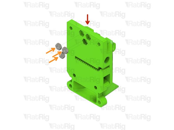
back_cartesian printed part
-
M3 Hex Nut
-
Install an M3 hex nut into each of the three positions shown
-
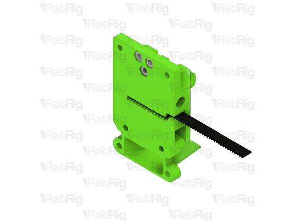
600mm 2GT 6mm Wide Timing Belt
-
Install one end of the timing belt into the printed part as shown
-
-
-
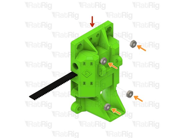
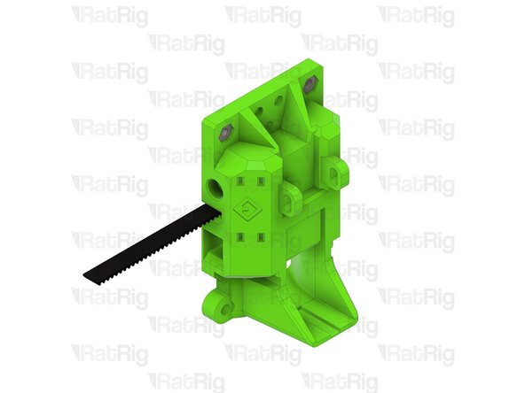
Assembly from Step 3
-
M3 Hex Nut
-
Install an M3 hex nut into each of the four positions shown
-
-
-
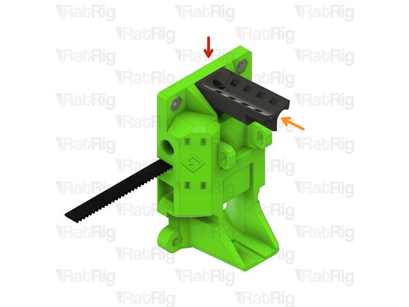
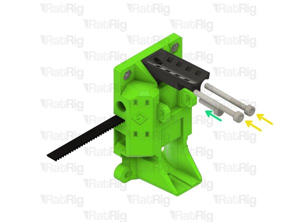
Assembly from Step 4
-
cartesian_cable_fin printed part
-
M3x30 Cap Head Screw
-
M3x12 Cap Head Screw
-
Take care not to over tighten the M3 screws as you can damage the printed parts
-
-
-
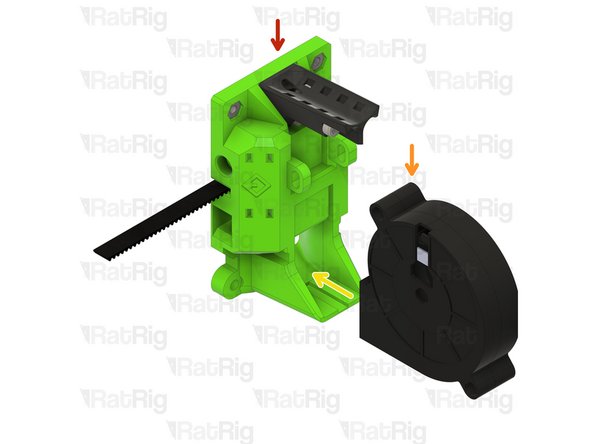
Assembly from Step 5
-
24v 5015 Blower Fan
-
Install the 5015 fan into the cartesian_back printed part as shown
-
M3x25 Cap Head Screw
-
M3 Hex Nut
-
Secure the fan in place by fitting the M3x25 screw and M3 hex nut as shown
-
Take care not to over tighten the M3x25 screw as you can damage the printed part
-
Set this assembly aside until Step 22
-
-
-
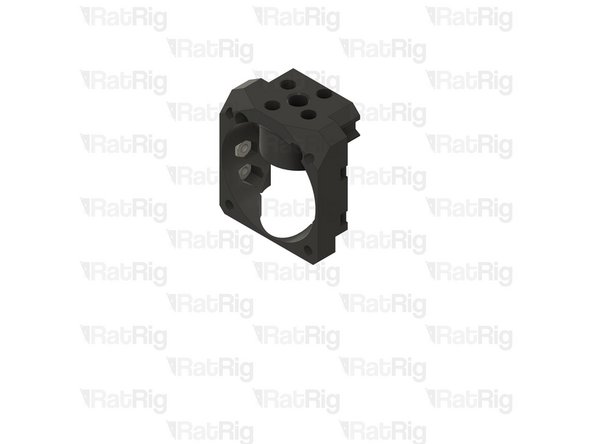
bmo_face printed part
-
1x Assembled Pheatus Dragonfly BMO hot end
-
Refer to the documentation supplied with the hot end for instructions on assembly
-
LJ8_probe_mount_8mm printed part
-
4x M3 Hex Nut
-
2x M3x8 Cap Head Screw
-
4x M2.5x8 Cap Head Screw
-
These screws are provided with the Pheatus Dragonfly BMO hot end
-
-
-
bmo_face printed part
-
M3 Hex Nut
-
Install an M3 hex nut into each of the two positions shown
-
M3 Hex Nut
-
Install an M3 hex nut into each of the two positions shown
-
-
-
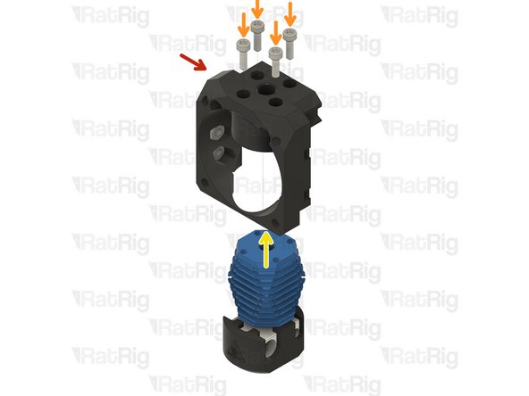
Assembly from Step 8
-
M2.5x8 Cap Head Screw
-
Assembled Pheatus Dragonfly BMO hot end
-
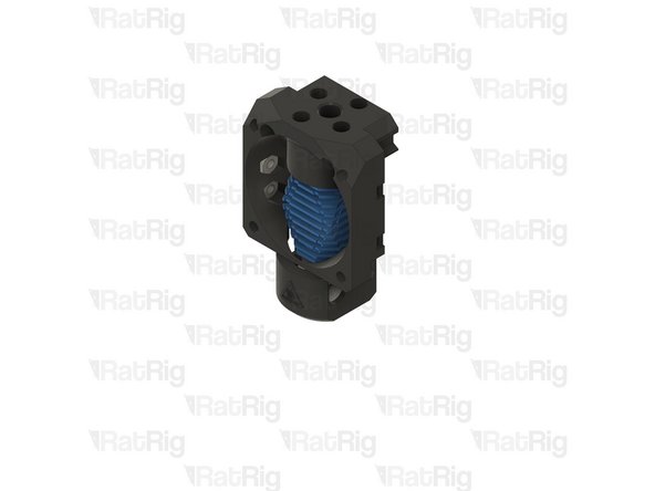
Secure the Pheatus Dragonfly BMO hot end to the printed part using the M2.5x8 screws
-
Take care not to over tighten the M2.5x8 screws as you can damage the printed parts or the threads in the hot end heatsink
-
-
-
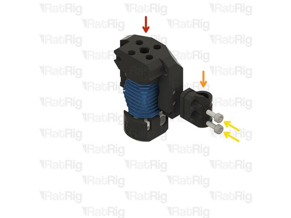
Assembly from Step 9
-
LJ8_probe_mount_8mm printed part
-
M3x8 Cap Head Screw
-
Loosely thread the M3x8 screws into the M3 nuts. Do not tighten them at this point
-
Set this assembly aside until Step 26
-
-
-
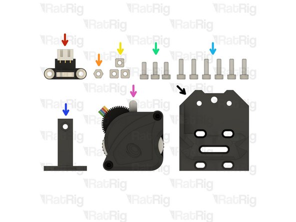
1x Limit Switch
-
1x M3 Hex Nut
-
3x M3 Square Nut (Included with the Bondtech LGX Lite)
-
3x M3x8 Cap Head Screw
-
6x M3x10 Cap Head Screw
-
top_endstop_angled printed part
-
1x Bondtech LGX Lite Extruder
-
top_mgn12_lgx_lite printed part
-
-
-
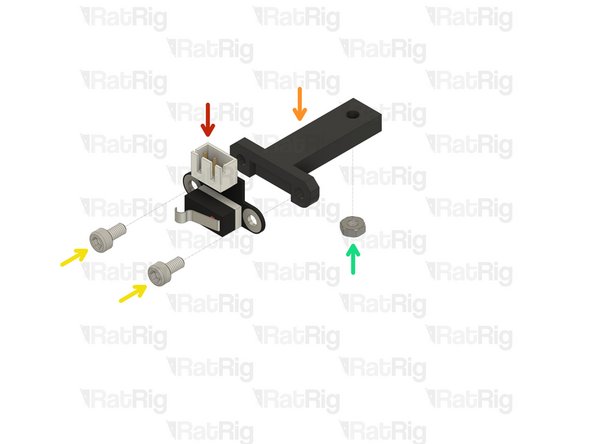
Limit Switch
-
top_endstop_angled printed part
-
M3x8 Cap Head Screw
-
Secure the limit switch to the printed part using the M3x8 screws
-
Take care not to over tighten the M3x8 screws as you can damage the printed part
-
M3 Hex Nut
-
Insert the M3 hex nut into the underside of the printed part
-
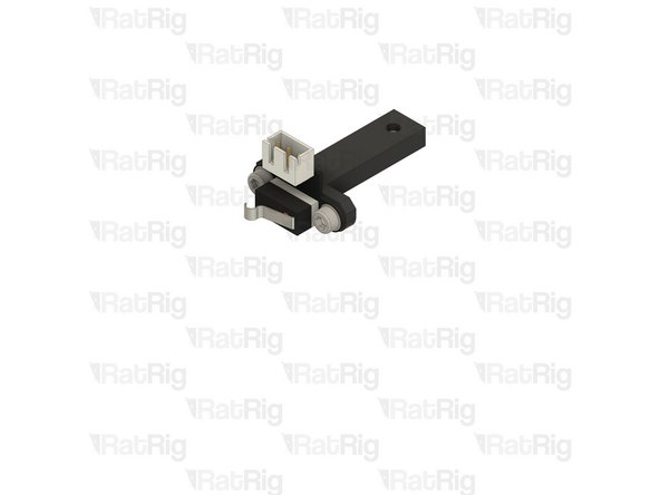
Set this assembly aside until Step 18
-
-
-
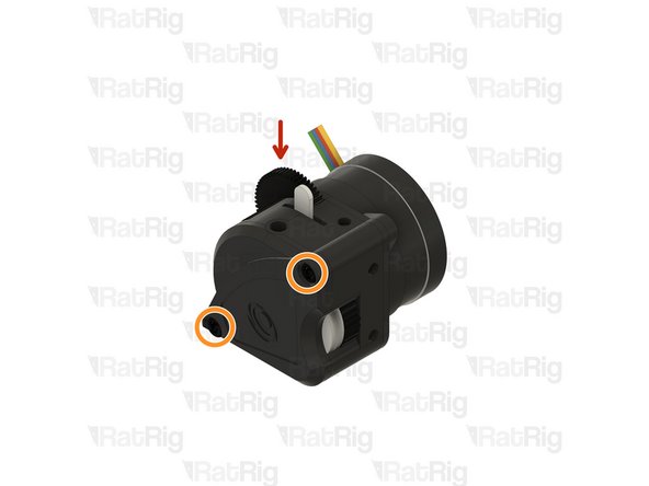
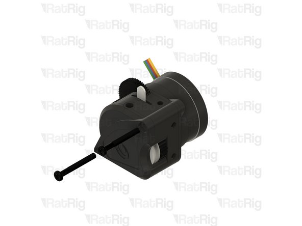
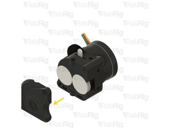
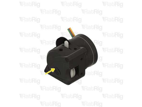
Bondtech LGX Lite extruder
-
Remove the two M3x25 screws holding the Bondtech LGX Lite together
-
Carefully remove the face plate from the LGX Lite assembly
-
-
-
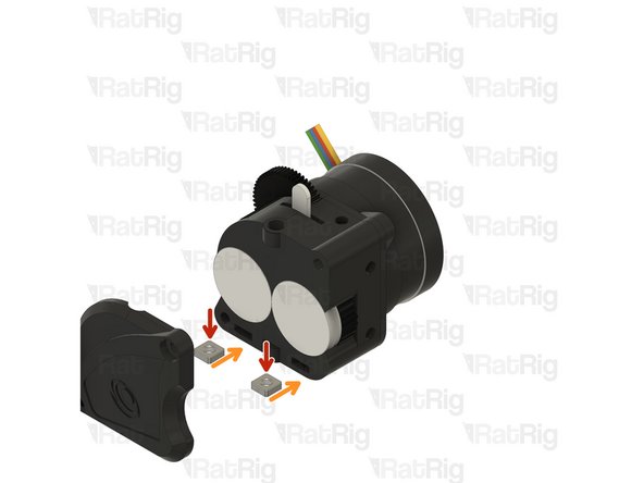
M3 Square Nut
-
Insert one M3 square nut into each of the marked holes on the LGX Lite
-
Re-install the LGX Lite face plate
-
-
-
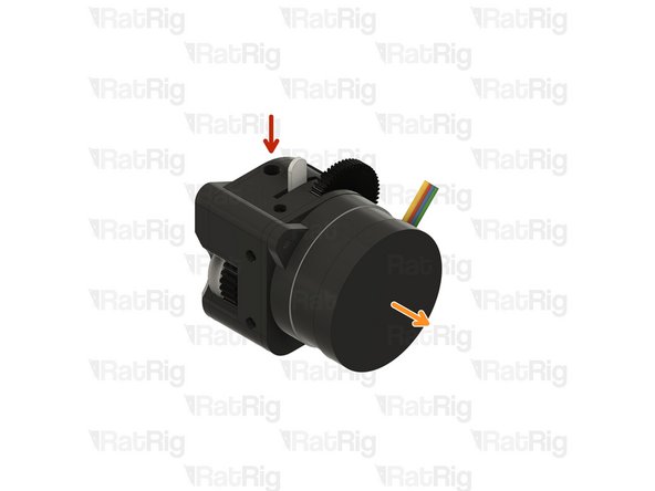
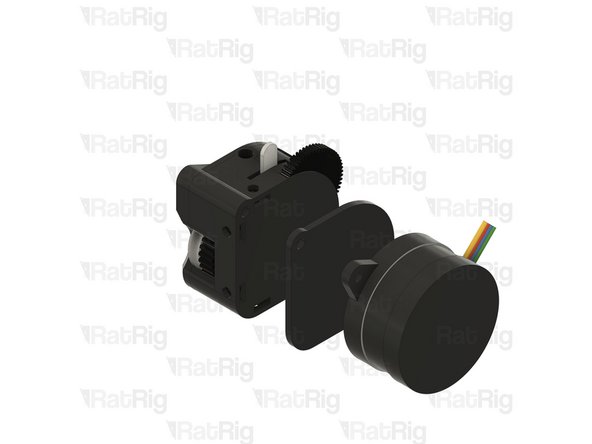
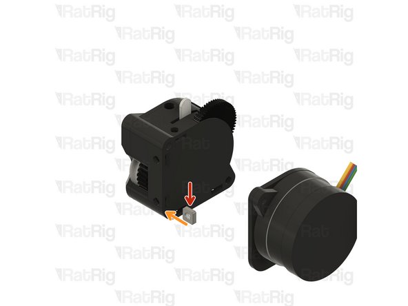
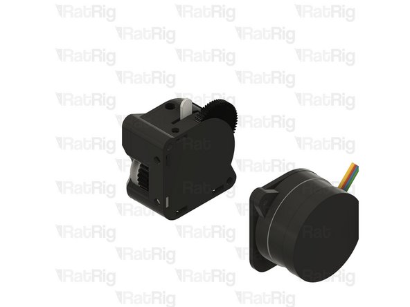
Bondtech LGX Lite extruder
-
Carefully separate the LGX Lite motor and back plate from the assembly as shown
-
-
-
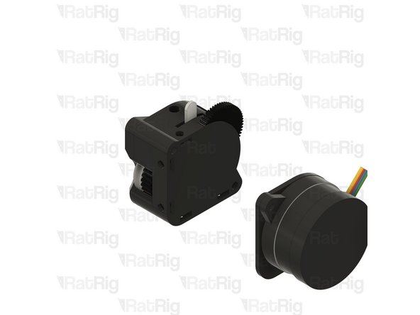
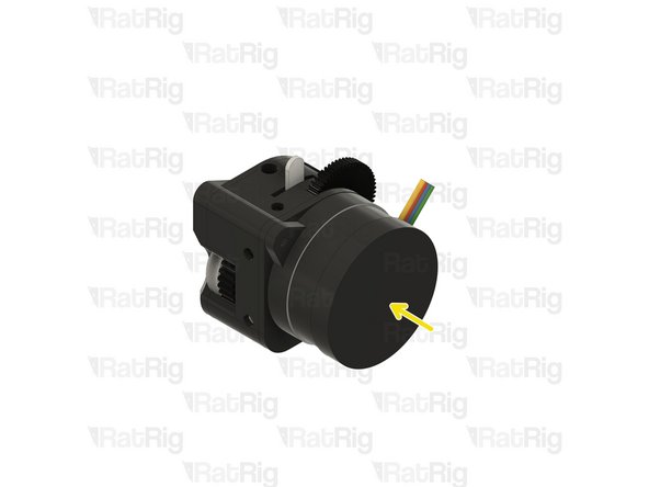
M3 Square Nut
-
Insert one M3 square nut into the marked hole on the LGX Lite
-
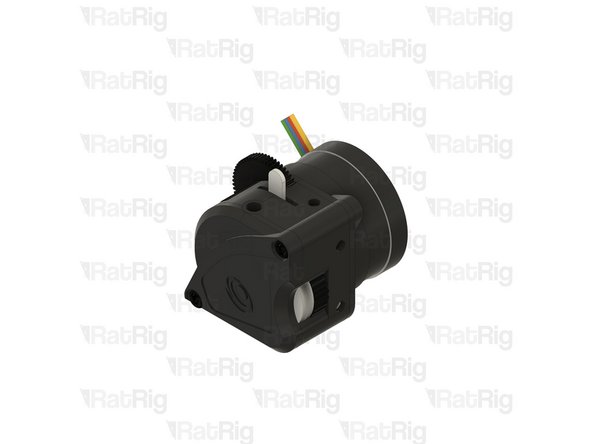
Re-install the LGX Lite back plate and motor
-
-
-
Re-install the two M3x25 screws, these secure the Bondtech LGX Lite together
-
Set the LGX Lite aside until Step 19
-
-
-
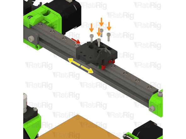
top_mgn12_lgx_lite printed part
-
M3x10 Cap Head Screw
-
Fasten all four M3x10 screws to secure the EVA top to the MGN12 carriage
-
Slide the X-axis left and right along the rail to make sure it moves smoothly
-
If the carriage binds at all, slightly loosen the M3x10 screws and check again
-
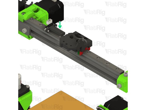
X-axis end stop assembly from Step 12
-
M3x8 Cap Head Screw
-
Insert the end stop assembly as shown and secure in place with the M3x8 screw
-
-
-
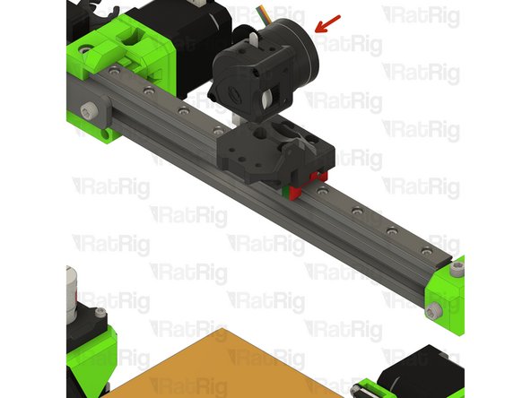
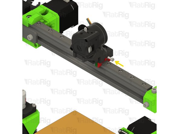
Bondtech LGX Lite extruder
-
M3x10 Cap Head Screw
-
M3x8 Cap Head Screw
-
Insert the three M3 screws as shown, fasten them to secure the LGX Lite extruder to the EVA top
-
Take care not to over tighten the M3 screws as you can damage the printed part
-
-
-
bottom_mgn12_short_duct printed part
-
bmo_support printed part
-
4x M3x35 Cap Head Screw
-
2x M3x25 Cap Head Screw
-
1x M3x6 Cap Head Screw
-
2x M3 Hex Nut
-
1x 53mm PTFE Tube
-
-
-
EVA face assembly from Step 2
-
Insert the EVA face into the EVA top as shown
-
M3x35 Cap Head Screw
-
Insert the M3x35 screws partially to hold the EVA face in place. They will be fully secured in the next step
-
-
-
EVA back assembly from Step 6
-
Align the EVA back with the top
-
Fully insert and fasten the M3x35 screws, securing the EVA back in place
-
Take care not to over tighten the M3x35 screws as you can damage the printed parts
-
-
-
bottom_mgn12_short_duct printed part
-
M3x35 Cap Head Screw
-
Position the EVA bottom_mgn12_short_duct printed part as shown
-
Secure it in place by inserting and fastening the M3x35 screws into the EVA back
-
Take care not to over tighten the M3x35 screws as you can damage the printed parts
-
-
-
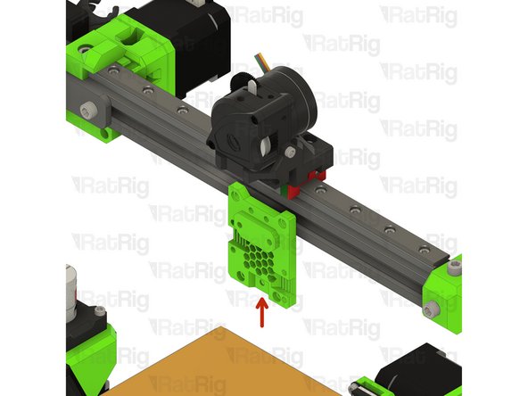
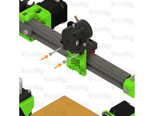
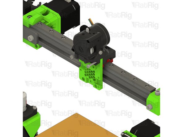
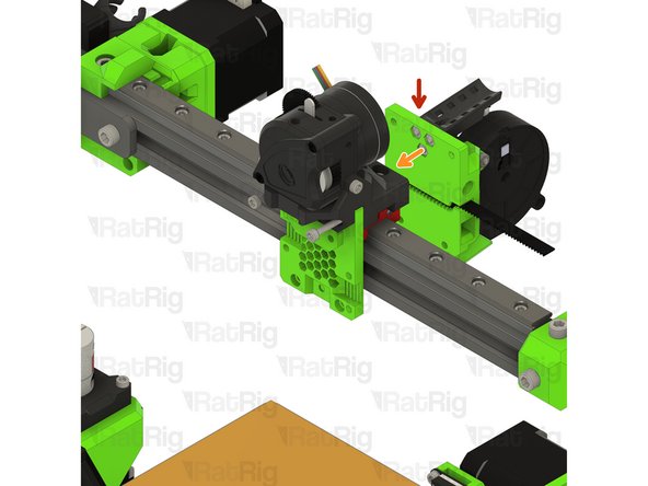
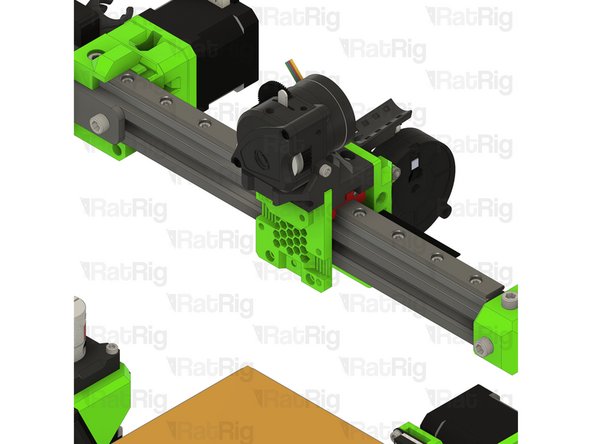
M3x10 Cap Head Screw
-
Insert and fasten the two M3x10 screws as shown to securely assemble the LGX Lite and EVA parts
-
Take care not to over tighten the M3x10 screws as you can damage the printed parts
-
-
-
bmo_support printed part
-
M3 Hex Nut
-
Install an M3 hex nut into each of the two positions shown
-
M3x6 Cap Head Screw
-
Secure the bmo_support part to the EVA face using the M3x6 screw
-
Take care not to over tighten the M3x6 screw as you can damage the printed parts
-
-
-
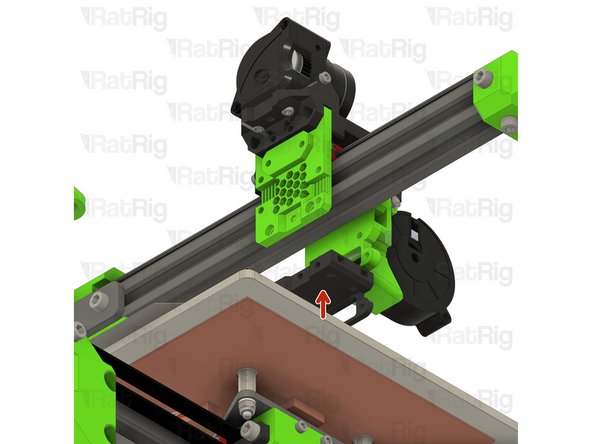
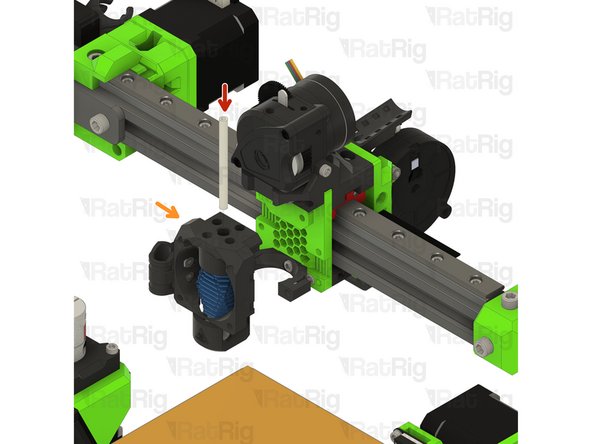
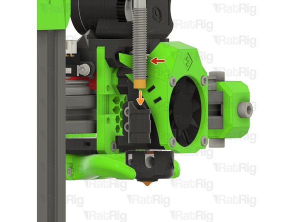
PTFE Tube - 53mm
-
Hot end assembly from Step 10
-
Insert the length of PTFE tube into the hot end assembly as shown
-
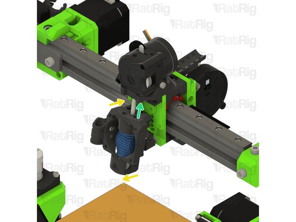
Rotate the hot end assembly as shown
-
Line up the end of the PTFE tube with the hole in the underside of the LGX Lite extruder mount and push the hot end assembly upwards
-
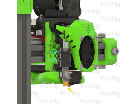
Rotate the bottom of the hot end assembly towards the EVA assembly
-
When properly lined up, the hot end assembly should rest atop the BMO-support printed part as shown
-
-
-
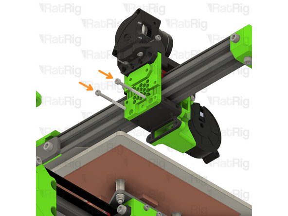
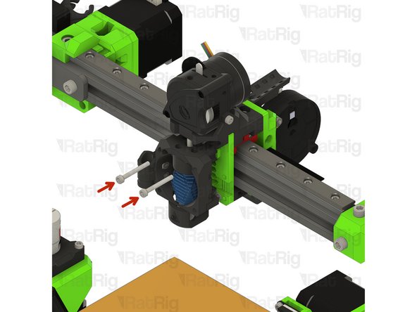
M3x25 Cap Head Screw
-
Insert the M3x25 screws through the hot end assembly fasten them to secure it to the EVA assembly
-
Take care not to over tighten the M3x25 screws as you can damage the printed parts
-
-
-
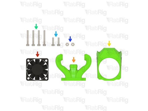
1x 40x10 24V Fan
-
trihorn_duct printed part
-
shroud printed part
-
The design of the EVA shroud may vary
-
4x M3x25 Cap Head Screw
-
2x M3x12 Cap Head Screw
-
2x M3 Hex Nut
-
-
-
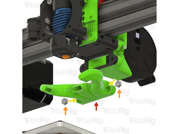
trihorn_duct printed part
-
M3 Hex Nut
-
Insert an M3 hex nut into each of the shown positions on the trihorn_duct
-
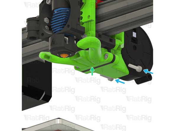
Position the trihorn_duct as shown
-
M3x12 Cap Head Screw
-
Insert the M3x12 screws as shown and fasten them to secure the trihorn_duct to the EVA assembly
-
Take care not to over tighten the M3x12 screws as you can damage the printed parts
-
-
-
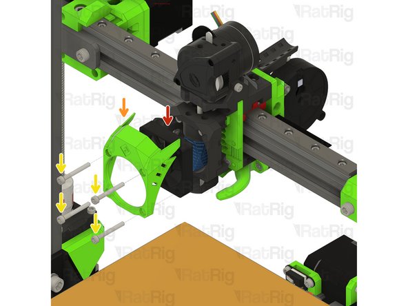
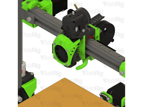
40x10 24V Fan
-
shroud printed part
-
M3x25 Cap Head Screw
-
Insert an M3x25 through each hole in the shroud as shown. Install the 40x10 fan onto the screws and then secure the shroud and fan to the EVA assembly.
-
Take care not to over tighten the M3x25 screws as you can damage the printed parts
-
-
-
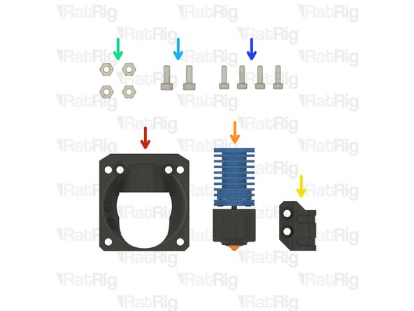
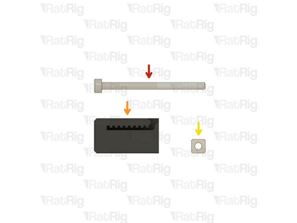
1x M3x40 Cap Head Screw
-
tension_slider_6mm_belt_M3s printed part
-
M3 Square Nut
-
-
-
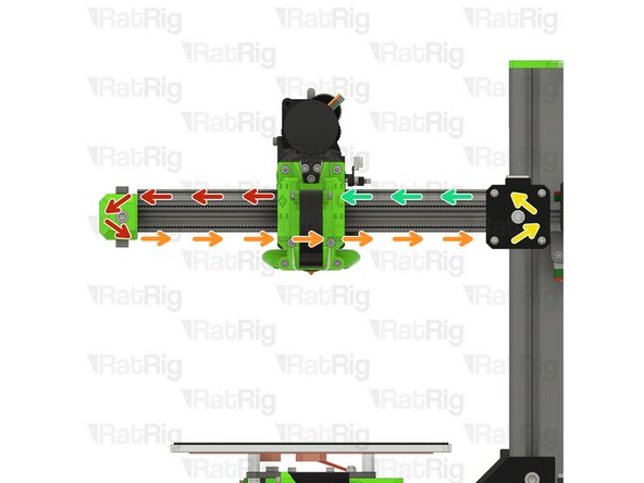
Take the free end of the X-axis timing belt and feed it around the idler pulley
-
Continue along the underside of the X-axis, passing through the hole in the EVA assembly
-
Feed it around the X-axis stepper motor pulley...
-
...and continue back to the EVA assembly
-
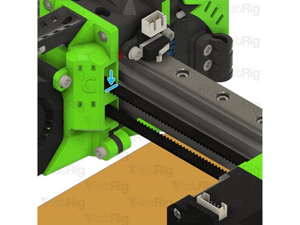
Pull the belt and mark where it meets the EVA assembly. This can be with a marker, or simply by holding it
-
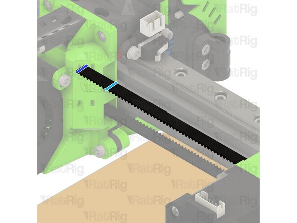
Measure 16mm, or count 8 teeth on the belt, from the position marked previously. Double check your measurements and then cut the belt at this point
-
The belt can be cut with regular scissors.
-
It is better to cut the belt too long than too short! If you are unsure, cut it longer than expected, you can always remove more if needed
-
-
-
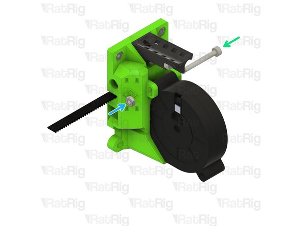
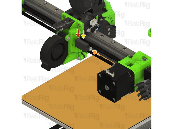
tension_slider_6mm_belt_M3s printed part
-
M3 Square Nut
-
Insert the M3 square nut into the end of the tension_slider printed part as shown
-
Cut end of 2GT 6mm timing belt
-
Insert the end of the belt into the printed part as shown
-
M3x40 Cap Head Screw
-
Insert the M3x40 screw into the EVA assembly as shown. This will be used to tension the belt in the next step
-
-
-
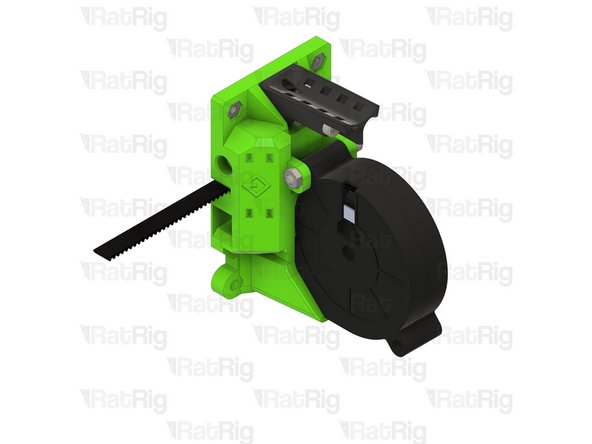
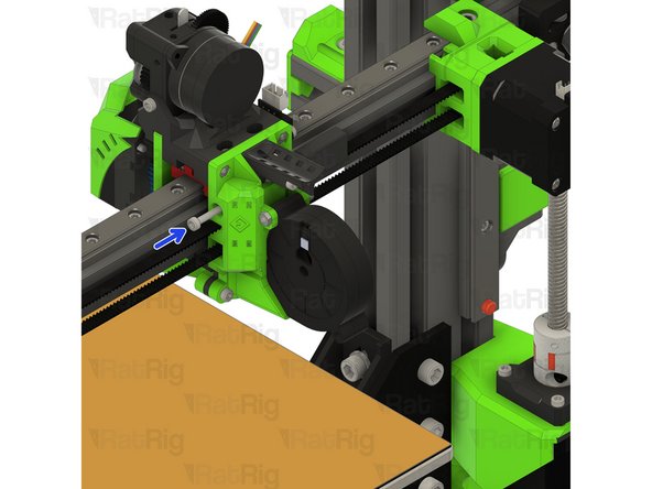
M3x40 Cap Head Screw
-
Fully insert the M3x40 screw as shown
-
Insert the tension_slider assembly into the EVA assembly as shown and secure by tightening the M3x40 screw
-
You can now adjust the tension of the X-axis belt:
-
Tighten the M3x40 screw to increase belt tension
-
Loosen the M3x40 screw to decrease belt tension
-
-
-
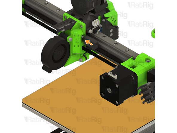
Slowly move the completed EVA assembly along the X-axis a few times. This will allow the pulley on the stepper motor to align itself
-
Secure the pulley to the stepper motor shaft by tightening both grub screws as shown
-
-
-
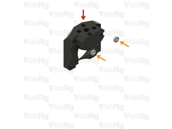
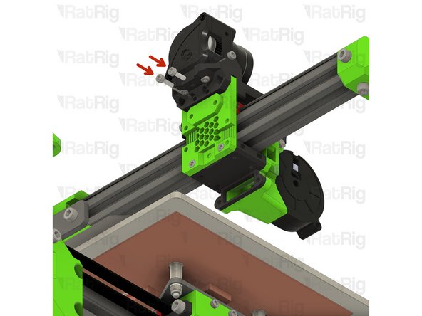
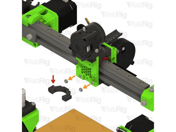
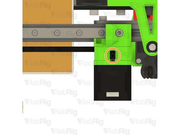
8mm Inductive Probe
-
Insert the probe as shown
-
Position the probe so that its tip is 1-2mm above the height of the nozzle
-
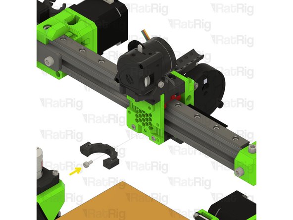
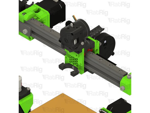
Secure the probe in place by tightening the two M3x8 screws
-


Cancel: I did not complete this guide.
17 other people completed this guide.