
Introduction
EVA is a modular carriage platform developed by Paweł Kucmus, Rat Rig and the EVA community, that allows you to use your favourite choice of extruder and hot-end on your Rat Rig 3D Printer.
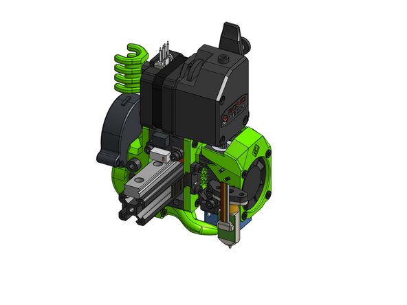
This tutorial covers one of the most popular EVA variants: Bondtech BMG + E3D V6. While many of the steps from the tutorial will be shared by other EVA variants, there may be some differences. This guide will show you the principles and basic EVA modules, so you can easily figure out how to assemble other variants if needed.
For more information on EVA see its documentation page and make sure the check out the community mods in the contributions page.
-
-
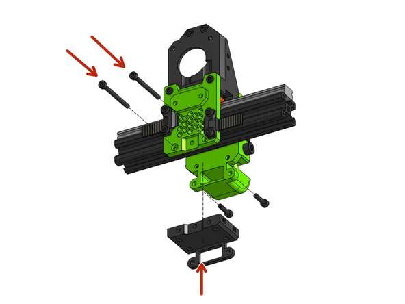
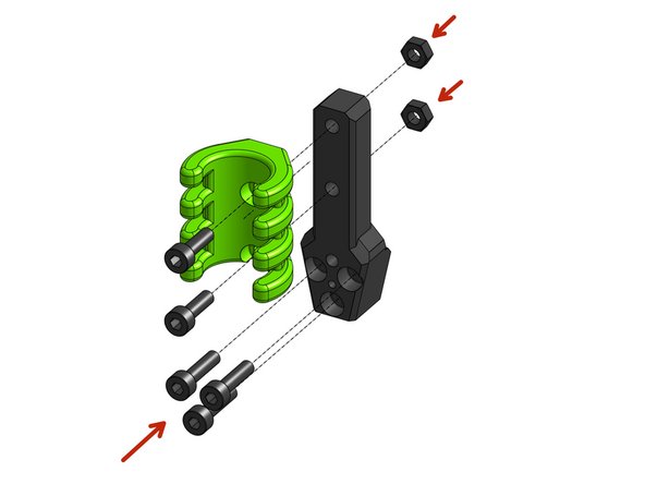
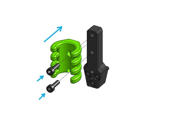
If you are using a limit switch as an endstop attach it to it's block part, M3x6mm screws are used in the case of the "angled" endstop switch
-
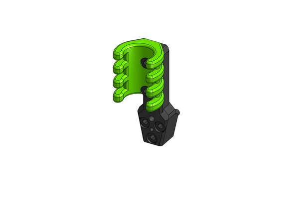
Attach the chosen endstop block with a M3x8mm screw and M3 nut
-
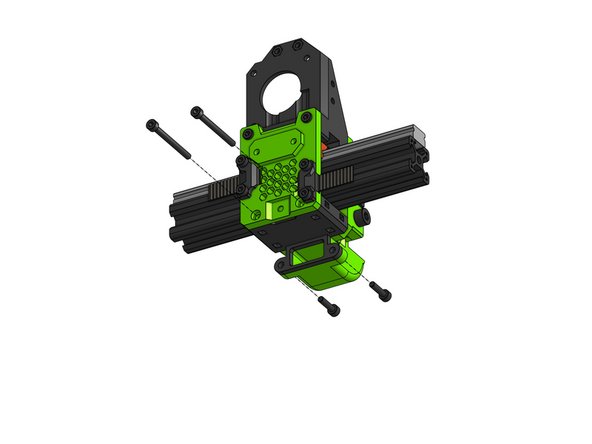
Back pull the remaining 4x M3 nuts - those are optional and maybe useful for future features
-
-
-
EVA is compatible with MGN12C, MGN12H and MGN15C
-
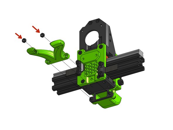
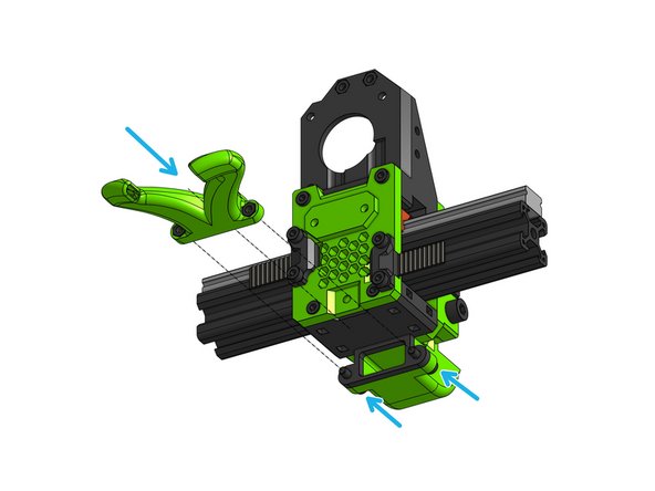
Attach the top part to the carriage with 4x M3x10mm
-
-
-
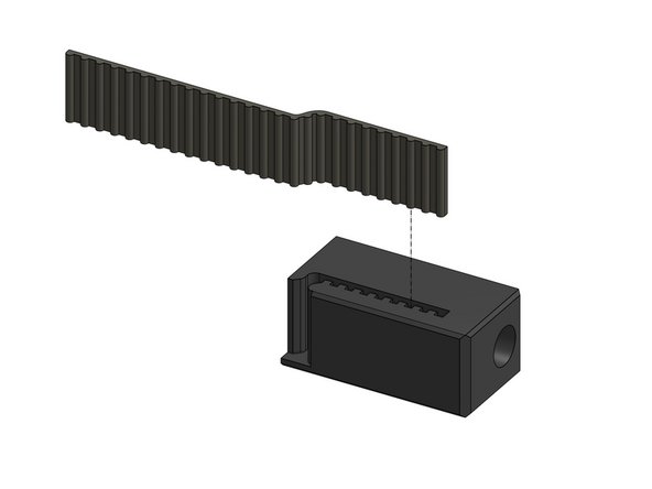
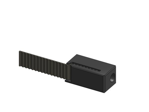
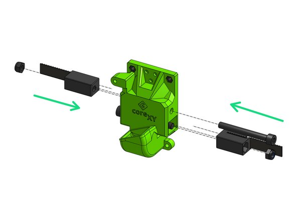
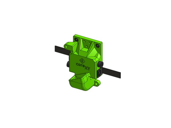
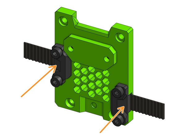
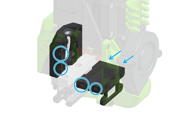
Slide the belts that are in the back of the X gantry into the tension blocks, repeat for 2 blocks
-
-
-
Back pull all M3 nuts:
-
3x M3 nuts for the cable holder
-
4x M3 nuts which will hold the back to the rest of the carriage
-
1x M3 nut holding the fan
-
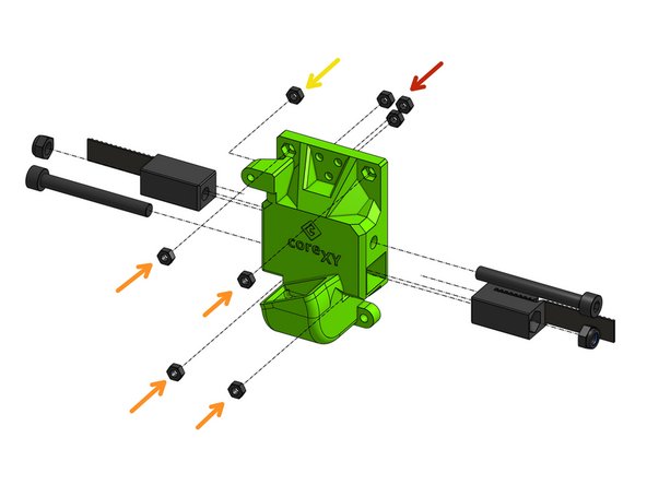
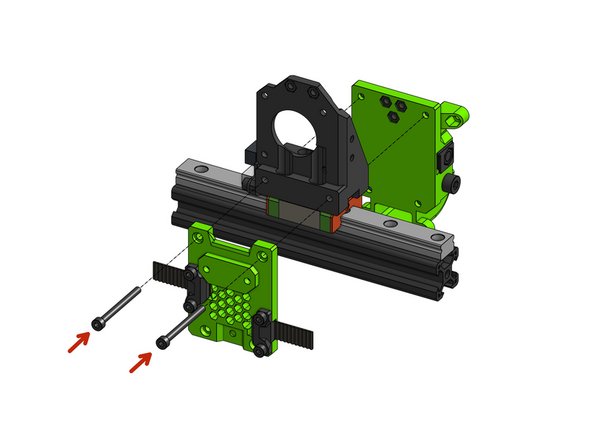
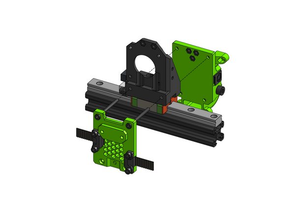
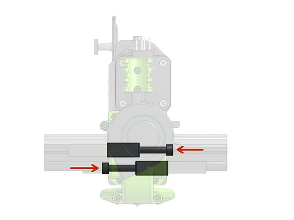
Assemble the belt tensioners with the M5 nuts and pull them in with the M5x45mm screws
-
-
-
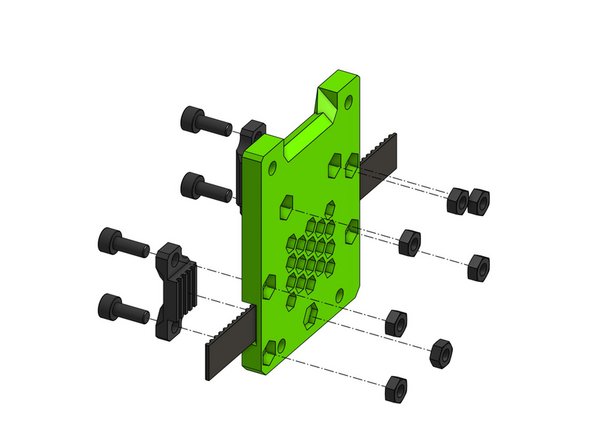
Back pull all of the M3 hex nuts on the back. The bottom-middle nut does not end up flush with the face of the part
-
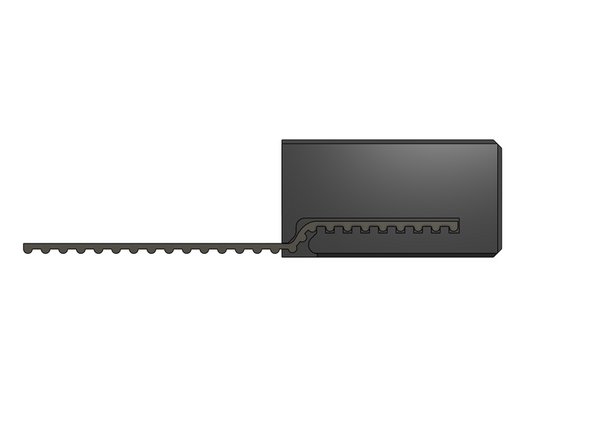
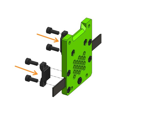
Attach the belt grabbers with M3x8mm. The belt does not have to end flush with the groove, it can go over it.
-
-
-
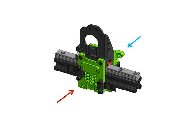
Fasten the front part to the top part with 2 M3x35mm screws.
-
Attach the back and tighten firmly.
-
-
-
Align the bottom part and fasten the front and back parts together through the bottom part with M3x35mm screws
-
Fasten the M3x12mm screws from the back, which will hold a fan duct.
-
-
-
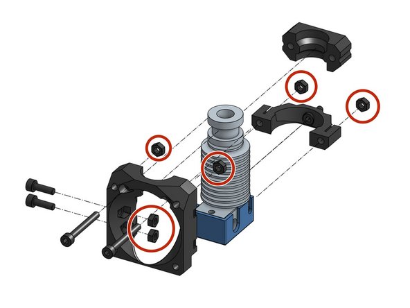
Push the 6 M3 hex nuts into the plastic parts
-
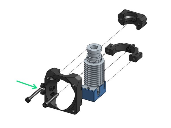
Attach the M3x10mm screws on the side. Leave them loose for now, they will be used to mount a bed probe.
-
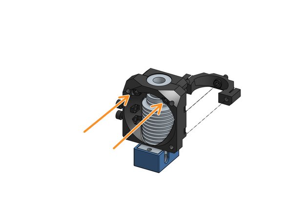
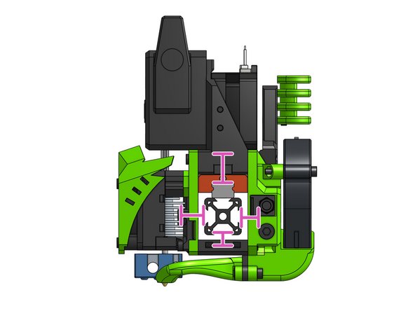
Align the face and clamp parts over the groove mount of the V6 and fasten them together with M3x25mm screws.
-
-
-
Attach the bottom support part to the front part with a M3x8mm screw
-
Attach the V6 face assembly
-
Fasten the face with the M3x25mm screws that are already in the face part
-
-
-
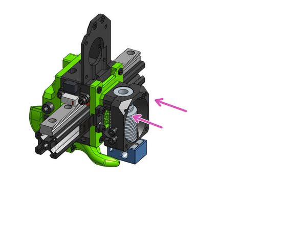
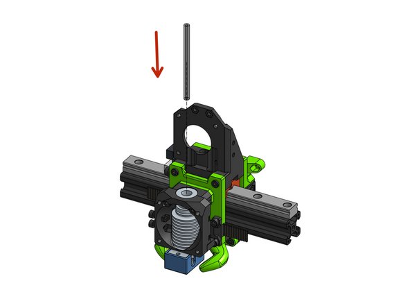
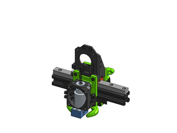
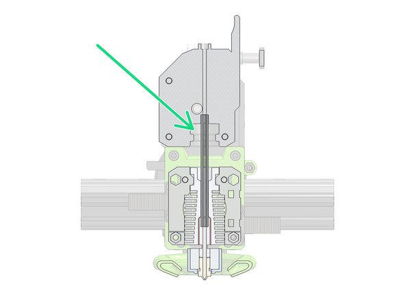
Insert a 62mm PTFE tube into the V6 hotend
-
Once the BMG is added to the carriage, this is where the tube will fit.
-
-
-
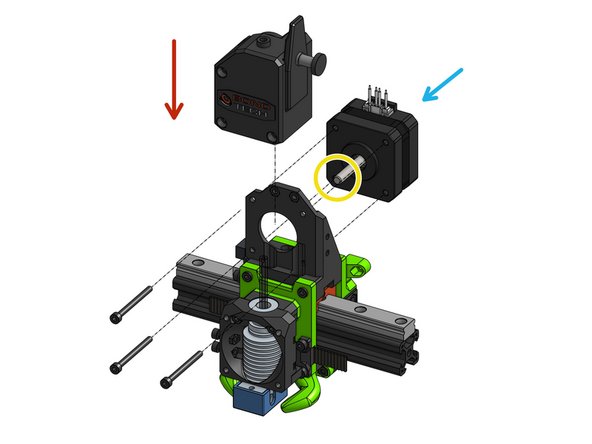
Slide the BMG on top of the PTFE tube
-
Attach the brass gear from the BMG package (not depicted) to the motor shaft
-
Slide the NEMA17 motor into the tom mount and the BMG
-
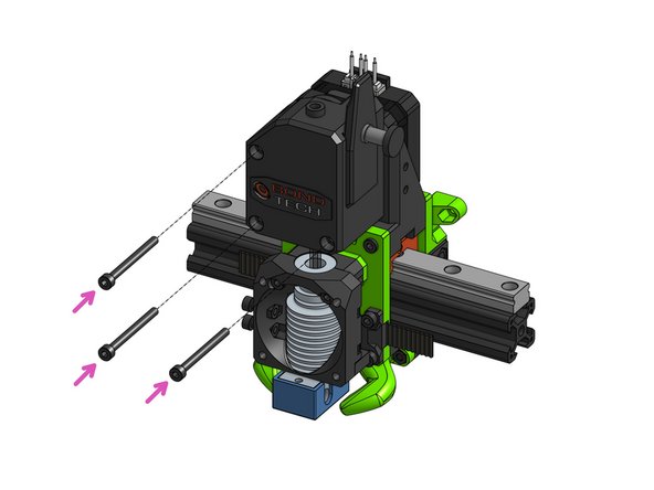
Fasten the BMG to the motor with M3x35mm screws
-
-
-
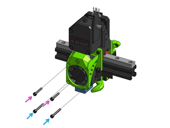
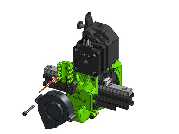
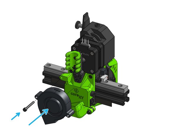
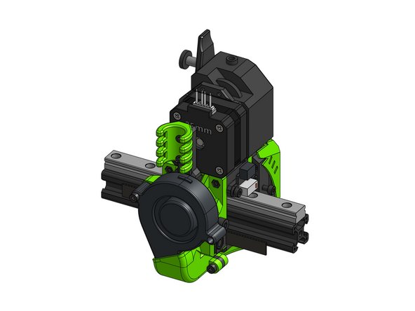
This step assumes a 4010 (40mm x 10mm fan) for a 4020 fan you need screws that are 10mm longer
-
Attach the fan and (optionally) the shroud to the face part with:
-
2x M3x25mm screws
-
2x M3x20mm screws
-
-
-
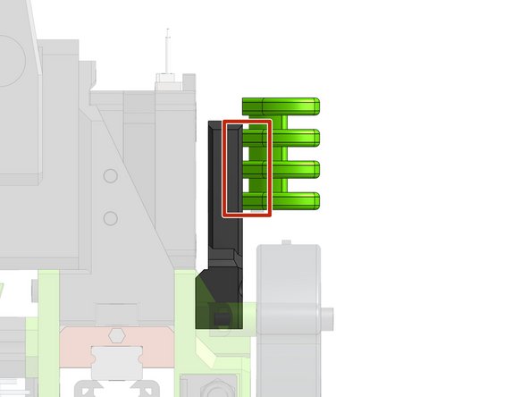
Attach the 2 M3 hex nuts and 3 M3x12mm screws
-
Attach the cable holder with 2 M3x10mm screws
-
-
-
Use zip ties to hold to the whole wire loom - this acts as a strain relief and prevents connectors from being pulled while printing. Use at least 2 zip ties to grab the loom in multiple points
-
You can use the designated slots for zip tying the heater and thermistor wires
-
Make sure all your wires stay away from the rail, as this could lead to damage.
-
-
-
Use the M5x45mm screws to tighten the XY belts
-
It's essential that the X gantry remains square after tensioning!
-
Make sure you keep tensioning until you get rid of all belt slack, and stop tensioning as soon as there's none.
-
If you have difficulties assessing if both belts are equally tensioned, measuring the vibration frequency of each belt and adjusting tension until frequencies match may be a helpful tool.
-
If the belts are too loose you might see some defects like ringing in the print surface. Ringing can be caused by acceleration and jerk settings too, so adjusting belt tension alone isn't likely to solve a ringing problem.
-
You can find a comprehensive article on CoreXY belt tensioning here.
-
-
-
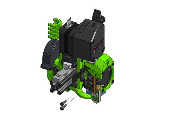
For BL-Touch, use the screws included in the packaging to attach the probe to the printed mount.
-
Fasten the probe to the face of the carriage with the two M3x10mm screws that are already in the assembly.
-


Cancel: I did not complete this guide.
36 other people completed this guide.

7 Comments
I can't find any instructions for the lgx lite and the rapido. Does anyone know if it exists anywhere?
Demetrio nunez - Resolved on Release Reply
I also had a hard time when it came to figuring out how to assemble EVA. I am using the Mosquito magnum and bondtech LGX. I found the Onshape cad link on the EVA page which helped quite a bit. You can see where the parts go and which screws to use. Without the cad files I would have been lost.
I suggested that the EVA developers would add a couple of open or exploded views of their non-deprecated combo’s. Also there is no conclusive picture or advise how to route the heater and thermistor wires. It’s a bit of a gamble. Last but not least the thermistor and heat-block fitting in the Mosquito hot-end are not snug, they can’t be tightened either
Flip Breukers - Resolved on Release Reply
I concur with the previous comments that the illustrated example is not one of the Ratrig appreciated standards. I chose the LGX-Lite and Mosquito Magnum setup (which is similar to the Mosquito setup) but hard a hard time conversing the illustrated example to my chosen setup. At last I used both CAD views of both to get an idea which screws and nuts to use. The fitting of the PTFE tube is way different from the illustrated example. For the mosquito the printed mount has a (slightly too tight) center hole. There you have to squeeze in the PTFE tube. Adding it afterwards (starting at the extruder) introduces the risk of a clogging gap on the Mosquito side. Then the whole Mosquito + mount construct has to be pushed through another hole in the LGX-Lite mount which can only be done after the LGX-Lite is bolted on the mount (from the underside. It’s impossible to adjust the PTFE tube after the LGX-Lite has been attached.
Flip Breukers - Resolved on Release Reply
All the previous steps were quite easy, and good explainedbut this one is just horrible.
The default configuration of the kit is (currently) the Bondtech LGX Lite Extrudert with the Phaetus Rapido UHF Hotend and even figuring out which orientation the parts should be in is really difficult.
I’m unable to find any documentation how the mounting of other extruders/hotends is supposed to work, the best hints how to fit this together I’m currently getting from images or renders.
According to the estimate this should take ~45 minutes, and I’m currently at the 3 hour mark, with no idea if what I’ve currently have done is correct.
I think I have managed to figure out the correct orientation of hte parts for the extruder and I’m currently struggeling with hotend. I don’t have even the slightest idea how I have to mount it.
I’m really frustrated right now and have to search for images of the eva with a rapido just to get hints on what to do…
Frustrated User - Resolved on Release Reply