Reputation over time
It looks like this user hasn't gained any reputation yet.
Once they have, you'll be able to view a graph of their reputation gained over time.
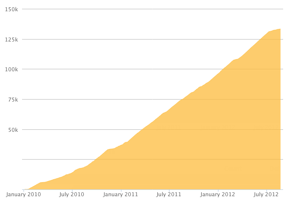
Here's a preview of what the graph will look like:
Reputation Breakdown
No reputation gained yet.
300
The first batch Vcores (3.0) were having cables with JST PHP6P connectors on the stepper motor side and Dupont connectors on the controller board side. The correct plug in of the Dupont connectors (when you're not changing them for JST XH2,54's) is from left to right (on the Octopuses) (left is where the covered power connector is): Black, Green, Red, Blue. The Black cable is facing the Y left stepper plug and the blue cable is facing the Z stepper plugs.
This is a good moment to install a base panel. I wired the Z-stepper motors (wire in the extrusion) after that I installed the base panel and the trims. I routed the stepper wires to the backside and tie ripped them temporarily to the electronic panel. This way I don't have to flip over the frame to install the wires to the Z-steppers later ion.
I suggested that the EVA developers would add a couple of open or exploded views of their non-deprecated combo’s. Also there is no conclusive picture or advise how to route the heater and thermistor wires. It’s a bit of a gamble. Last but not least the thermistor and heat-block fitting in the Mosquito hot-end are not snug, they can’t be tightened either
I concur with the previous comments that the illustrated example is not one of the Ratrig appreciated standards. I chose the LGX-Lite and Mosquito Magnum setup (which is similar to the Mosquito setup) but hard a hard time conversing the illustrated example to my chosen setup. At last I used both CAD views of both to get an idea which screws and nuts to use. The fitting of the PTFE tube is way different from the illustrated example. For the mosquito the printed mount has a (slightly too tight) center hole. There you have to squeeze in the PTFE tube. Adding it afterwards (starting at the extruder) introduces the risk of a clogging gap on the Mosquito side. Then the whole Mosquito + mount construct has to be pushed through another hole in the LGX-Lite mount which can only be done after the LGX-Lite is bolted on the mount (from the underside. It’s impossible to adjust the PTFE tube after the LGX-Lite has been attached.
For the LGX Lite- Mosquito combo there is 34.6 mm PTFE (or Capricorn) tube needed. 18mm + 16.6 mm
I have the Mosquito Magnum. I opened the CAD view and the thermistor and heater slots have to face front. Don’t forget to push in some Capricorn or other PTFE tube. This has to connect the extruder with the hot-end and form the filament path of the DD setup. Reason to insert it here (for the Mosquito that is) is that the Mosquito is fixed under the carrier and the PTFE tube goes through it. To ensure a snug fit I first ran the tube (Capricorn) through the center hole into the tube fitting on top of the Mosquito. Then I gently pushed the hot-end up and fastened the screws. This way I pushed the PTFE tube “back up“ without a gap on the hot-end side (potential clog point).
M3 x 12 will fit if the nut is pushed or melted in deep enough.
Applying force to push the nuts in can crack the printed part when the nut space is near the edge. I chose to heat the nut with a soldering tip (250 degrees celcius) and gently melt them in.
The Jig from Adam works perfect.
The two front lead screws fell in without any adjustment. The back one though. There was no room for wiggling the complete motor carriage (bottom plate was a snug fit. Luckily the stepper motor mount had just enough wiggle space to adjust it the 0.5 mm it needed to fit in the coupler.
It is advisable to pull the nuts in from the back on the back arm in order to be able to perform the next step.
Page 1 of 3
Next