-
-
This procedure can be found on the OpenBuilds Documentation, for further information click here.
-
Follow this step if you don't have access to a multimeter. Otherwise, Skip to Step 2.
-
If the two wires you joined together belong to the same coil, the shaft will become significantly harder to turn by hand.
-
If that shaft still spins easily, you have not identified a coil yet, and you must try a different combination of wires.
-
If you join together two wires that do result in the motor presenting resistance against turning, you can label these two wires as belonging to the same coil.
-
-
-
This procedure can be found on the OpenBuilds Documentation, for further information click here.
-
Set your multimeter to Continuity / Diode Test mode.
-
Start with any random wire, and touch that to the Black/Negative probe on your multimeter.
-
Select any remaining wire and touch it with the Red/Positive probe of your multimeter:
-
If the multimeter shows [1 or 0L] it means “no connection” - indicating we did not find a coil between these two wires. Some multimeters also “beep” when it does find a connection, so if there is no beep noise, it also could indicate the coil is not between these two wires.
-
If you see a reading on the multimeter. The actual number does not matter too much, it's more important that it has some low value reading, and that the multimeter no longer displays [1] on the display. Some multimeters may “beep” when you have continuity between the wires (circuit completed by the coil in between).
-
Segment off these two wires and label them as belonging to a coil. It's important to not lose track of the coil pairs.
-
-
-
Xtension Connector - 4 Pin
-
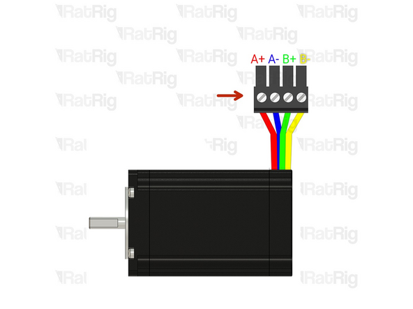
Insert an Xtension connector (male) onto the stepper wires. The previously identified coil pairs must be next to each other. They are now designated as A pair and B pair. The + and - don't really matter at this point as long as the coil ends are together.
-
Your stepper wire colours might be different, please proceed with the correct coil pairs for your set-up.
-
Repeat the coil identification step and this step for the remaining stepper motors.
-
-
-
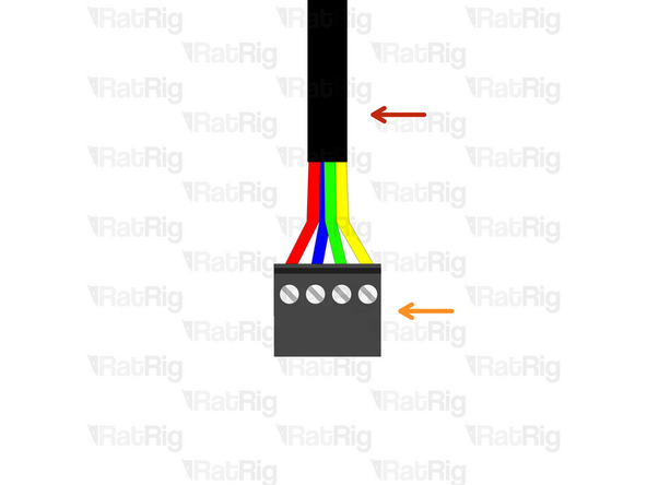
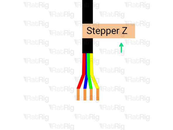
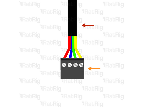
Prepare the 4 wire cable for the Z stepper motor.
-
4 Wire cable - [Entire length] (don't cut it)
-
Insert an Xtension (female) connector on to the cable end.
-
Connect the extension to the stepper motor.
-
Make sure to follow the wire colour scheme to preserve the motor coil pairs.
-
Should the integrity of the motor coil pairs not be maintained, the motor will experience impaired operational functionality.
-
-
-
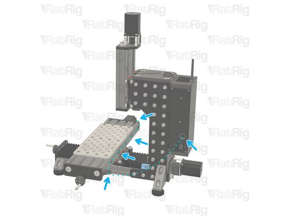
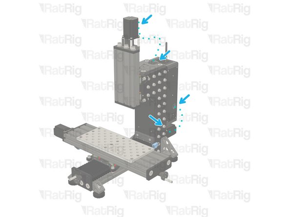
Route the Z-stepper wires as shown in the picture.
-
Use a zip tie to constrain it to the mill_stepper_cable_managment printed part, then through the mill_z_tower_top printed part and inside the Z tower. Finally exit at the rear, above the Y stepper and into the electronics enclosure or your desired location. Leave an extra 300mm (at least) to route it to the controller and crimp the connector.
-
Cut the cables to the final length, double check if the cable has the appropriate length to reach the final position of your electronics enclosure before cutting.
-
Label the cable at the end, with a piece of duct tape for example.
-
-
-
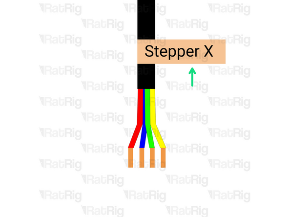
Prepare the 4 wire cable for the X stepper motor.
-
4 Wire cable - [Entire length] (don't cut it)
-
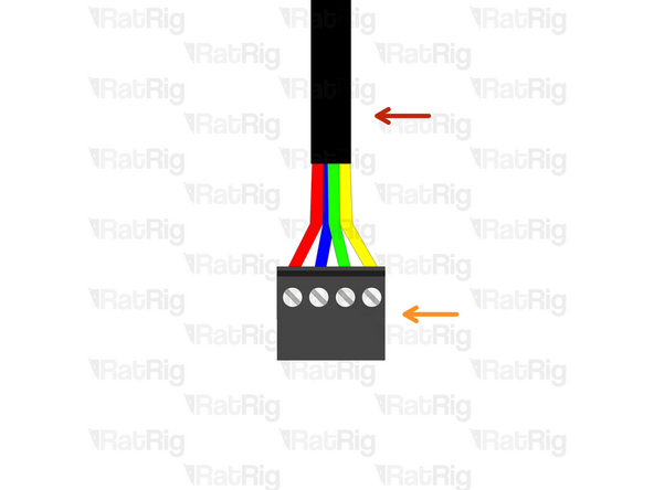
Insert an Xtension (female) connector on the cable end.
-
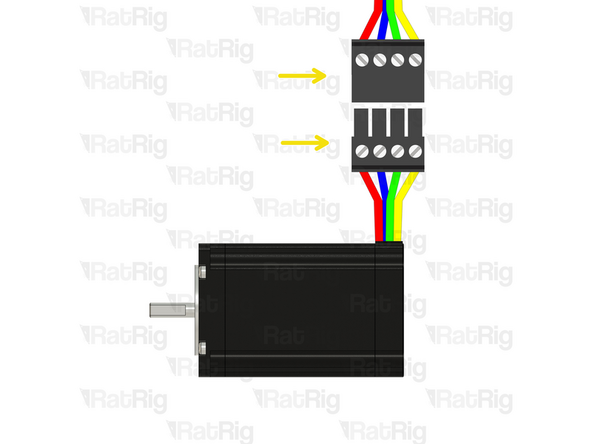
Connect the extension to the stepper motor.
-
Make sure to follow the wire colour scheme to preserve the motor coil pairs.
-
Should the integrity of the motor coil pairs not be maintained, the motor will experience impaired operational functionality.
-
-
-
Route the X-stepper wires as shown in the picture.
-
Use a zip tie to constrain it to the mill_stepper_cable_managment printed part, through the 4016 X gantry using the mill_4040_t_slot_clip to secure them. Exit at the mill_x_umbilical_mount printed part, and into the electronics enclosure or your desired location. Leave an extra 300mm (at least) to route it to the controller and crimp the connector.
-
Cut the cables to the final length, double check if the cable has the appropriate length to reach the final position of your electronics enclosure before cutting.
-
Label the cable at the end, with a piece of duct tape for example.
-
-
-
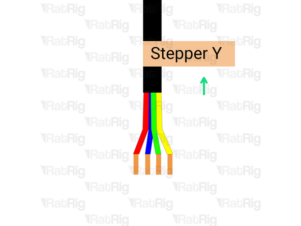
Prepare the 4 wire cable for the Y stepper motor.
-
4 Wire cable
-
Insert an Xtension (female) connector on the cable end.
-
Connect the extension to the stepper motor.
-
Make sure to follow the wire colour scheme to preserve the motor coil pairs.
-
Should the integrity of the motor coil pairs not be maintained, the motor will experience impaired operational functionality.
-
-
-
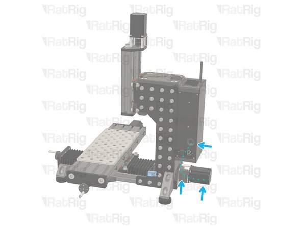
Route the Y-steppers cables as shown in the picture.
-
Use a zip tie to constrain it to the mill_stepper_cable_managment printed part, and into the electronics enclosure or your desired location. Leave an extra 300mm (at least) to route it to the controller and crimp the connector.
-
Cut the cables to the final length, double check if the cable has the appropriate length to reach the final position of your electronics enclosure before cutting.
-
Label the cable at the end, with a piece of duct tape for example.
-
-
-
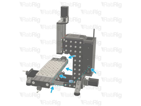
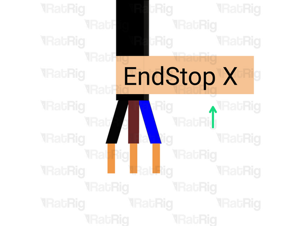
Route the X endstop cable as shown in the picture.
-
Use a zip tie to constrain it to the mill_stepper_cable_managment printed part, through the 4016 X gantry using the mill_4040_t_slot_clip to secure them. Exit at the mill_x_umbilical_mount printed part, and into the electronics enclosure or your desired location. Leave an extra 300mm (at least) to route it to the controller and crimp the connector.
-
Cut the cables to the final length, double check if the cable has the appropriate length to reach the final position of your electronics enclosure before cutting.
-
Label the cable at the end, with a piece of duct tape for example.
-
-
-
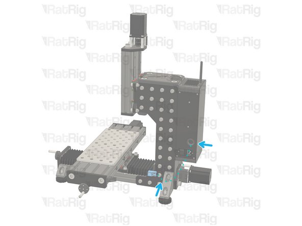
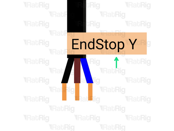
Route the Y endstop cable as shown in the picture.
-
Cut the cables to the final length, double check if the cable has the appropriate length to reach the final position of your electronics enclosure before cutting.
-
Label the cable at the end, with a piece of duct tape for example.
-
-
-
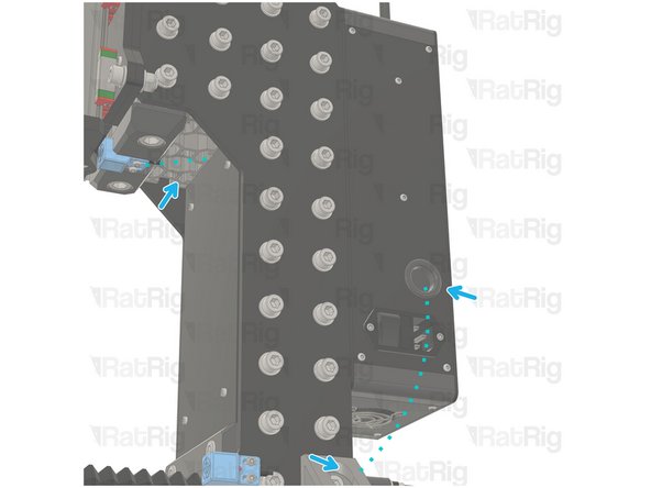
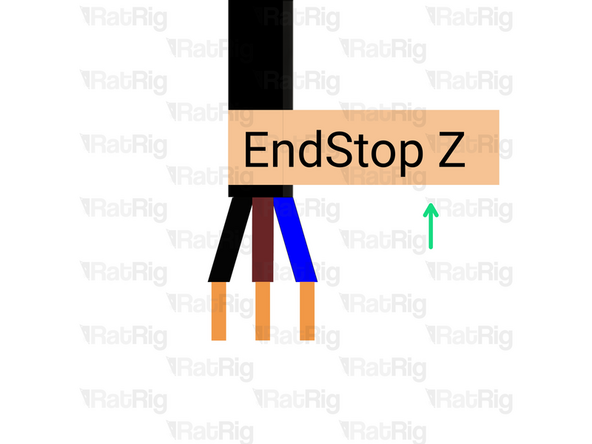
Route the X endstop cable as shown in the picture.
-
Use a zip tie to constrain it to the mill_z_endstop_mount printed part, then through the extrusion slot. Finally exit at the rear, above the Y stepper and into the electronics enclosure or your desired location. Leave an extra 300mm (at least) to route it to the controller and crimp the connector.
-
Cut the cables to the final length, double check if the cable has the appropriate length to reach the final position of your electronics enclosure before cutting.
-
Label the cable at the end, with a piece of duct tape for example.
-
Almost done!
Finish Line


![4 Wire cable - [Entire length] (don't cut it)](https://d3t0tbmlie281e.cloudfront.net/igi/ratrig/fJ1nWtRLIKCMbEnj.medium)
![4 Wire cable - [Entire length] (don't cut it)](https://d3t0tbmlie281e.cloudfront.net/igi/ratrig/GkLjWtRLTFK2W6xu.medium)
