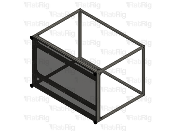
Introduction
Please note: The CNC Enclosure - Mill is not supplied with the enclosure panels, they must be sourced separately.
DXF and STEP files for the panels are available on the documentation website.
-
-
It is recommended to have the following tools available for assembling the CNC Enclosure - Mill:
-
Allen Key / Hex Wrenches in the following sizes: 3mm, 4mm & 5mm
-
A tape measure
-
A pair of scissors
-
-
-
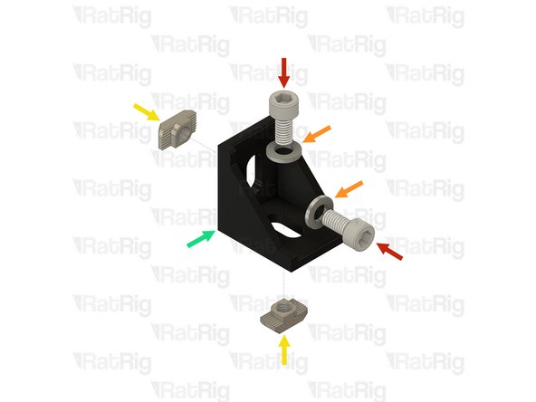
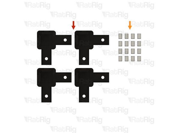
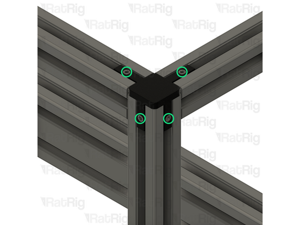
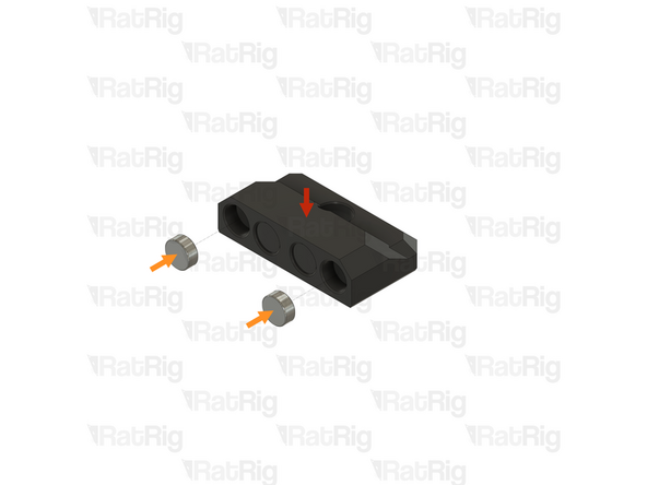
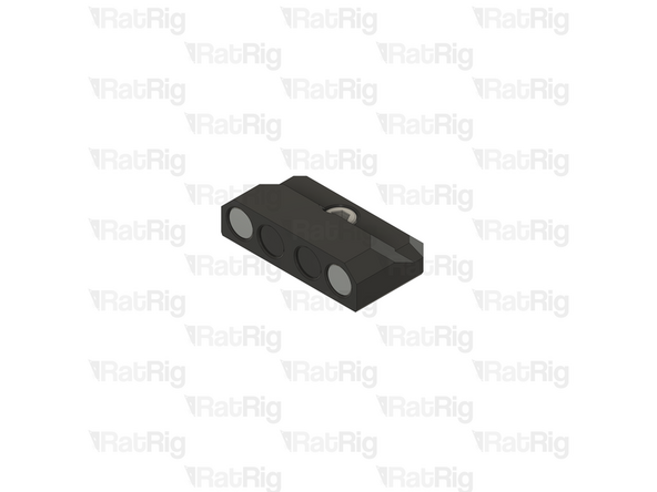
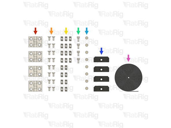
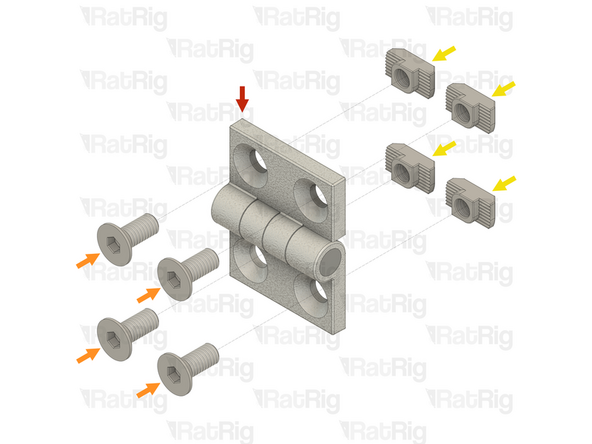
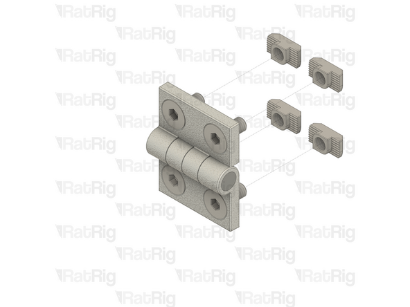
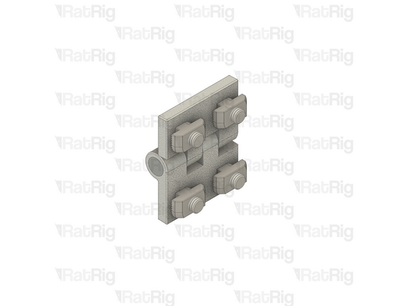
28x 3030 cast 90 degree corner
-
56x M6x12 cap head screw
-
56x M6 washer
-
56x T-nut drop-in for 3030 - M6
-
-
-
2x M6x12 cap head screw
-
2x M6 washer
-
2x T-nut drop-in for 3030 - M6
-
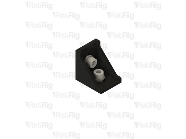
1x 3030 cast 90 degree corner
-
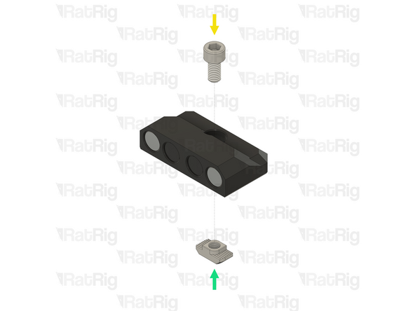
Loosely thread a 3030 T-nut on to each M6x12 screw. Do not tighten them at this point
-
-
-
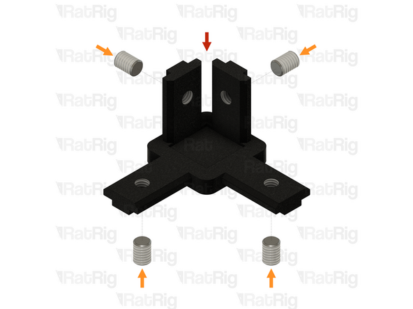
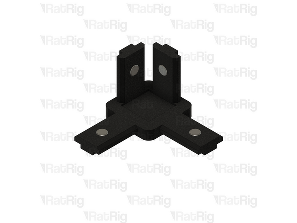
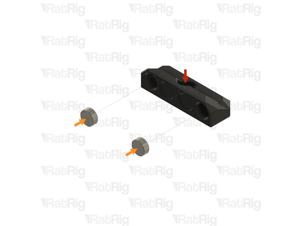
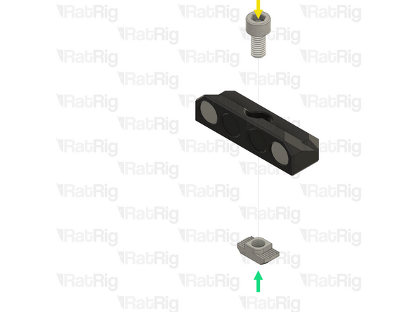
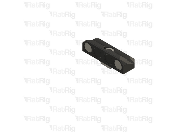
1x Inside hidden three way corner
-
4x M6x8 set screw
-
Insert an M6x8 set screw into each of the holes on the inside corner as shown
-
Set these assemblies aside until Step 17
-
-
-
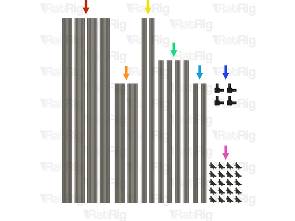
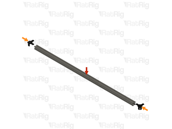
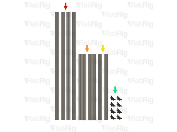
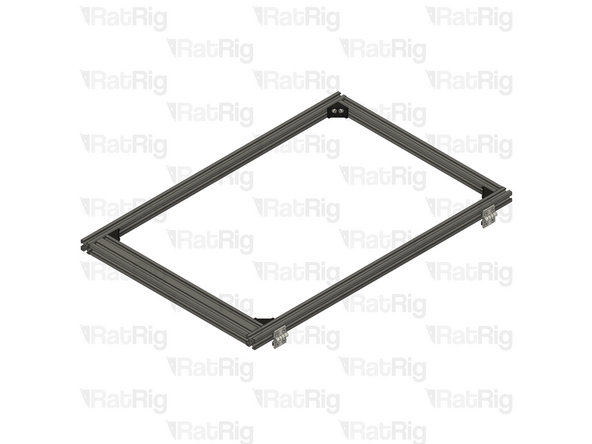
4x 1102mm 3060 extrusion
-
2x 712mm 3060 extrusion
-
2x 1102mm 3030 extrusion
-
4x 850mm 3030 extrusion
-
2x 712mm 3030 extrusion
-
4x Inside hidden three way corner assemblies
-
20x 3030 cast 90 degree corner assemblies
-
-
-
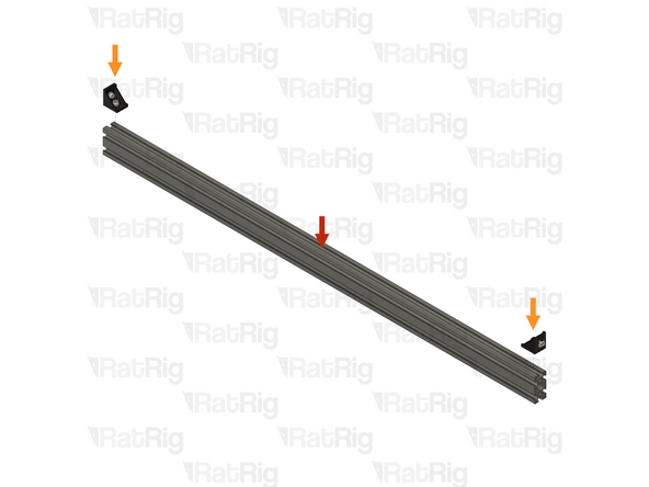
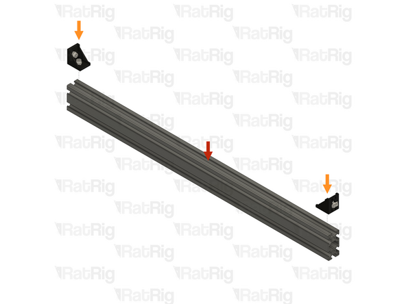
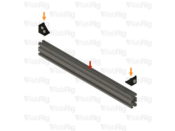
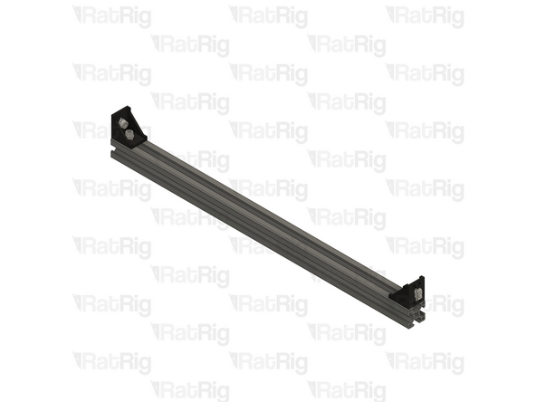
1x 1102mm 3060 extrusion
-
2x 3030 cast 90 degree corner assemblies
-
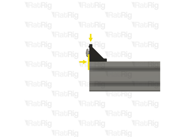
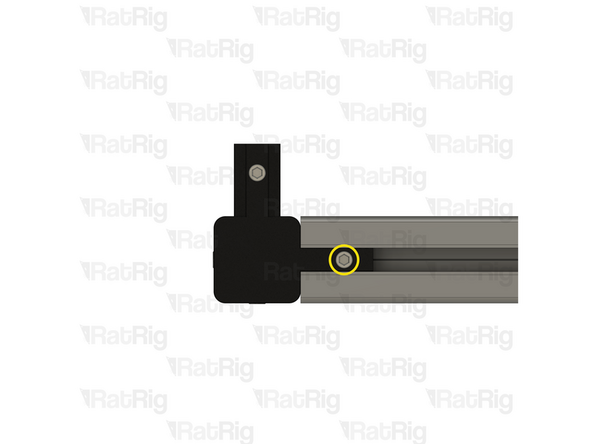
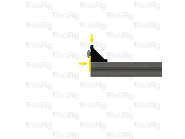
Install one corner assembly onto each end of the 1102mm 3060 extrusions as shown. Tighten the M6x12 screw to secure them.
-
Ensure the corner assemblies are flush and square with the ends of the extrusions after tightening the screws
-
Set these assemblies aside until Step 9
-
-
-
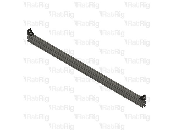
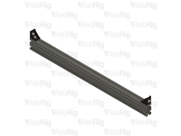
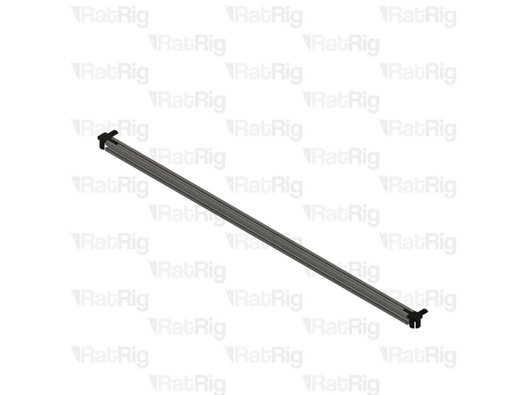
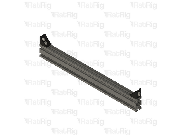
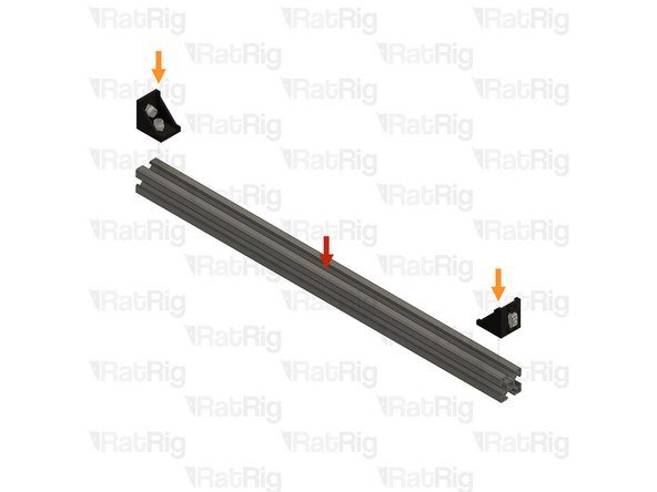
1x 712mm 3060 extrusion
-
2x 3030 cast 90 degree corner assemblies
-
Install one corner assembly onto each end of the 712mm 3060 extrusions as shown. Tighten the M6x12 screw to secure them
-
Ensure the corner assemblies are flush and square with the ends of the extrusions after tightening the screws
-
-
-
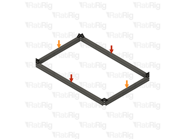
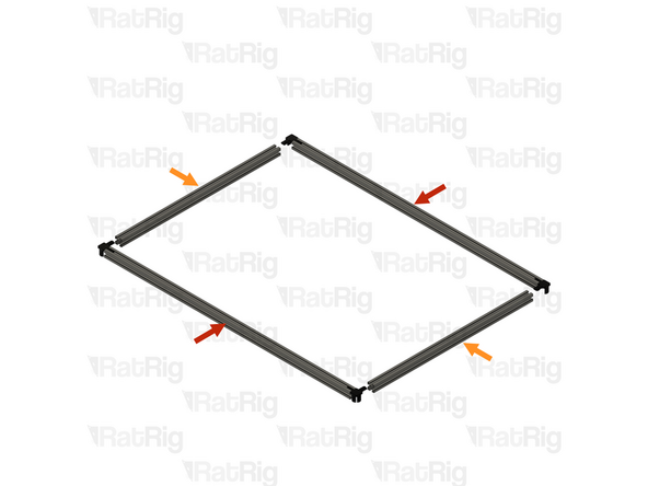
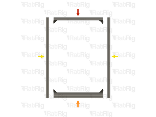
2x Bottom frame front & back assembly from Step 7
-
2x Bottom frame left & right assembly
-
Position the bottom frame assemblies as shown
-
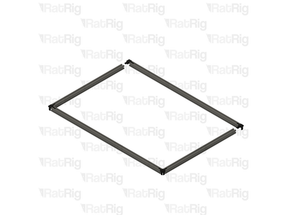
1x 850mm 3030 extrusion
-
Slot the 850mm 3030 extrusion into the corner of the bottom frame assemblies as shown, it will be secured in the next step
-
-
-
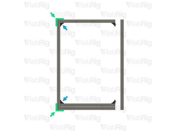
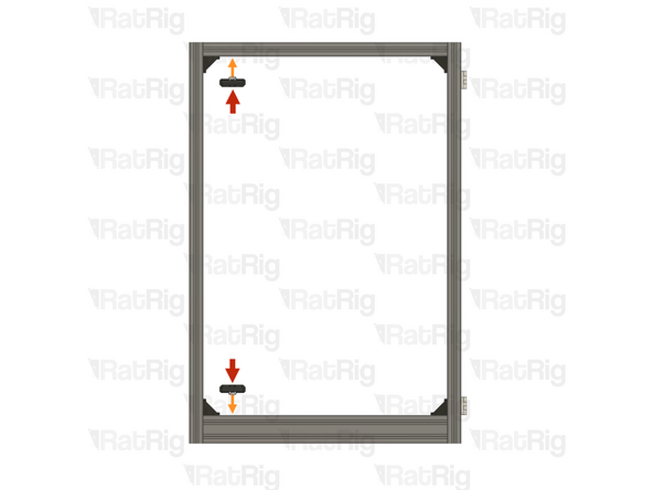
1x 850mm 3030 extrusion
-
Align the 850mm 3030 extrusion into the corner of the bottom frame assemblies as shown, make sure it is square
-
Make sure the end of the 850mm 3030 extrusion which has been tapped, faces downwards towards the bottom frame, otherwise you will be unable to install the feet in a later step
-
Tighten the marked M6x12 screws to secure the 850mm 3030 extrusion to the bottom frame
-
Repeat these instructions to install and secure the remaining 3x 850mm 3030 extrusions as shown
-
-
-
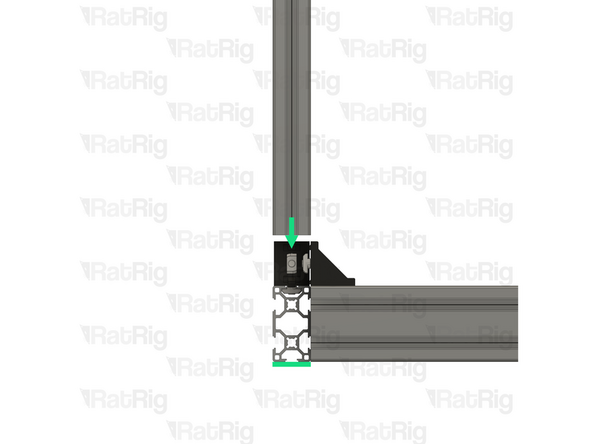
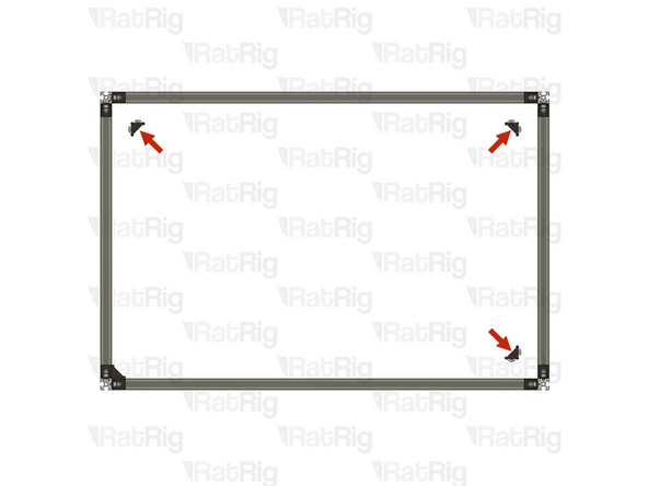
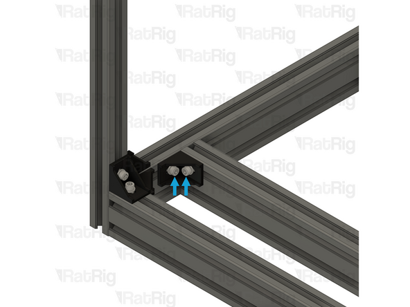
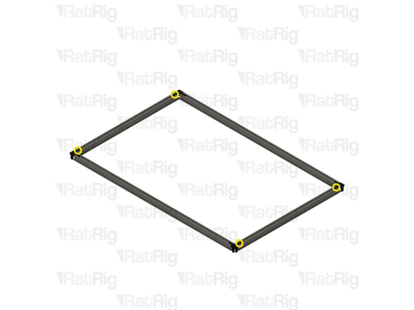
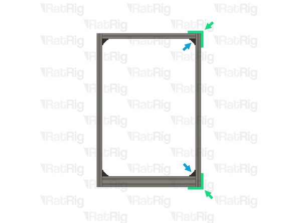
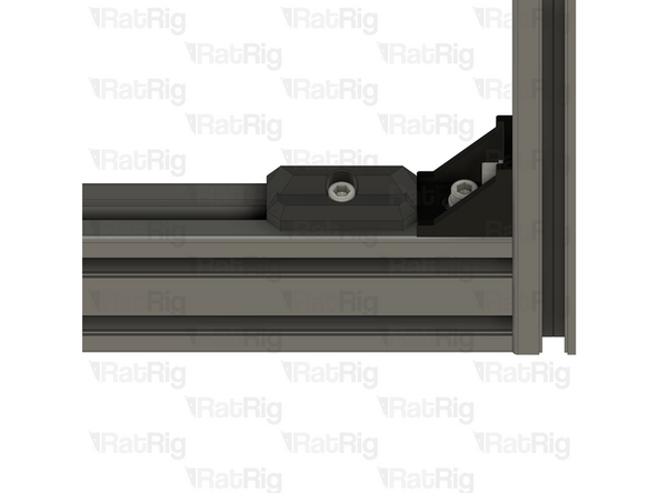
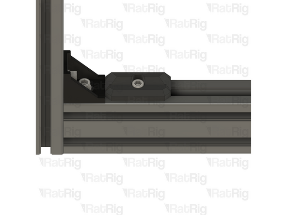
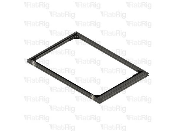
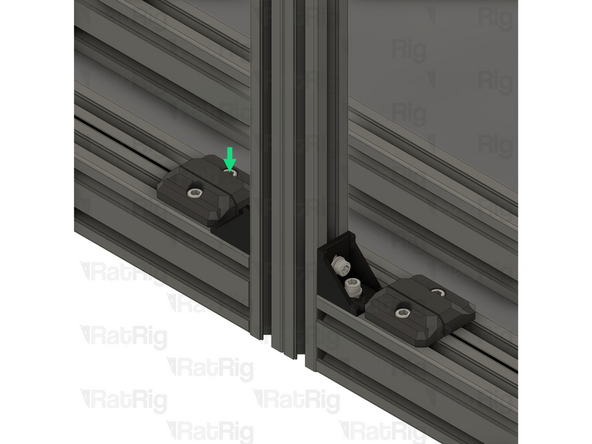
1x 3030 cast 90 degree corner assembly
-
Install a 3030 cast 90 degree corner assembly into the inner corner as shown
-
Tighten both M6x12 screws to secure the cast 90 degree corner to the frame assembly
-
-
-
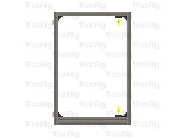
3x 3030 cast 90 degree corner assembly
-
Repeat the instructions in the previous step to install the remaining 3x 3030 cast 90 degree corner assemblies
-
-
-
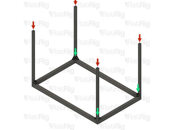
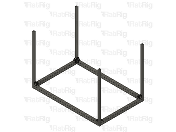
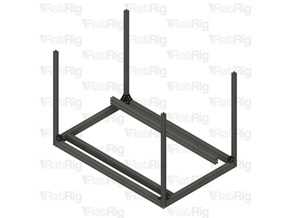
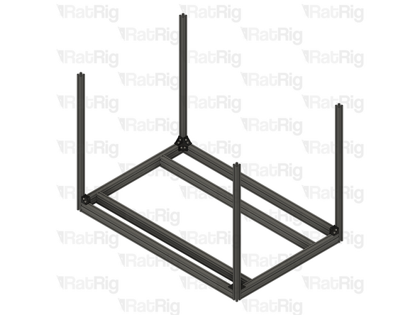
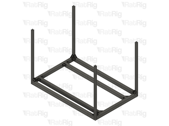
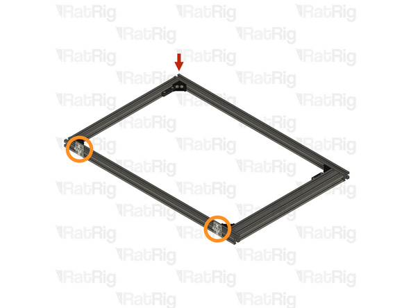
2x 1102mm 3060 extrusion
-
Place the 1102mm 3060 extrusions inside the bottom of the frame, they will be aligned and secured in the next steps
-
-
-
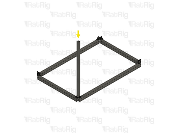
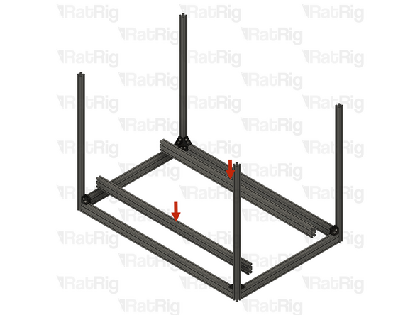
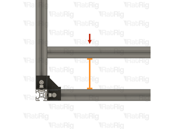
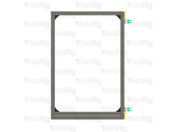
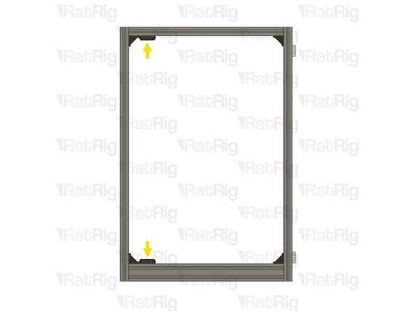
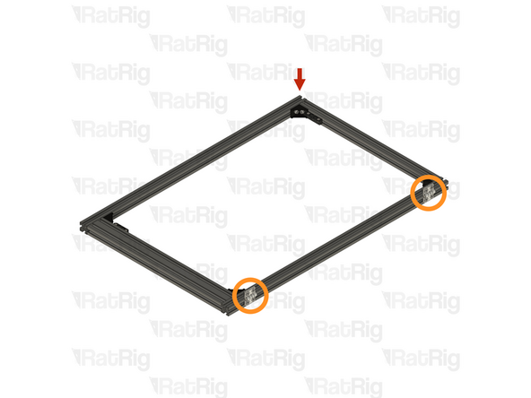
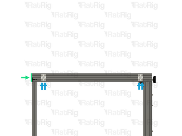
1x 1102mm 3060 extrusion
-
Position the extrusion so the marked gap measures 80mm
-
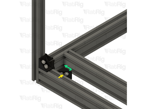
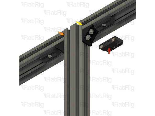
1x 3030 cast 90 degree corner assembly
-
Install a 3030 cast 90 degree corner assembly into the inner corner as shown
-
Tighten both M6x12 screws to secure corner assembly to the frame assembly
-
Double check the 80mm measurement once the 3030 cast 90 degree corner is secured
-
-
-
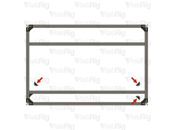
3x 3030 cast 90 degree corner assembly
-
Repeat the instructions in the previous step to install the remaining 3x 3030 cast 90 degree corner assemblies
-
-
-
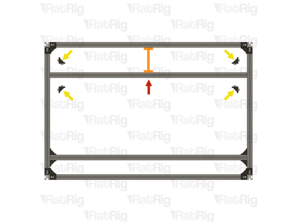
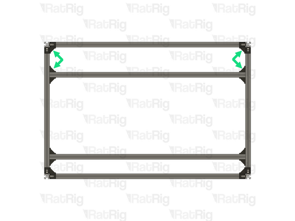
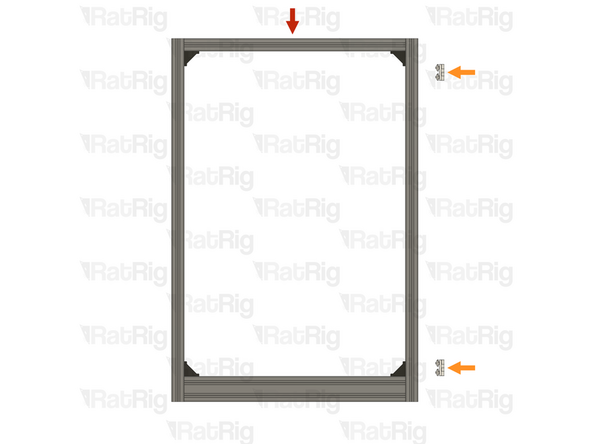
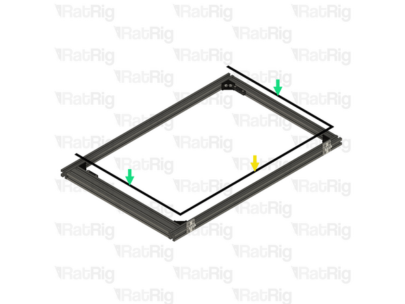
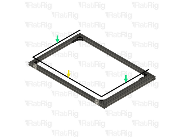
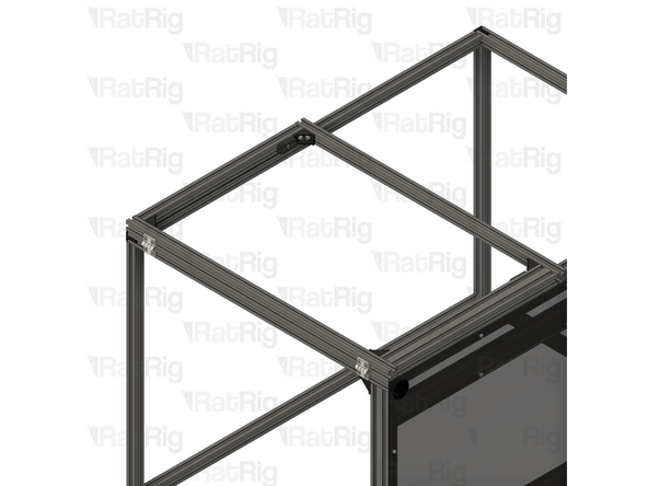
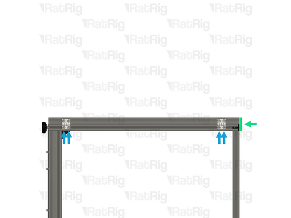
1x 1102mm 3060 extrusion
-
Position the extrusion so the marked gap measures 140mm
-
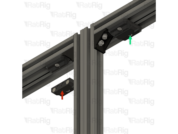
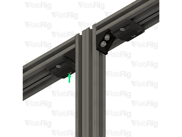
4x 3030 cast 90 degree corner assembly
-
Install a 3030 cast 90 degree corner assembly into each inner corner as shown
-
Tighten both M6x12 screws on each corner assembly to secure the frame together
-
Double check the 140mm measurement once the 3030 cast 90 degree corners are secured
-
-
-
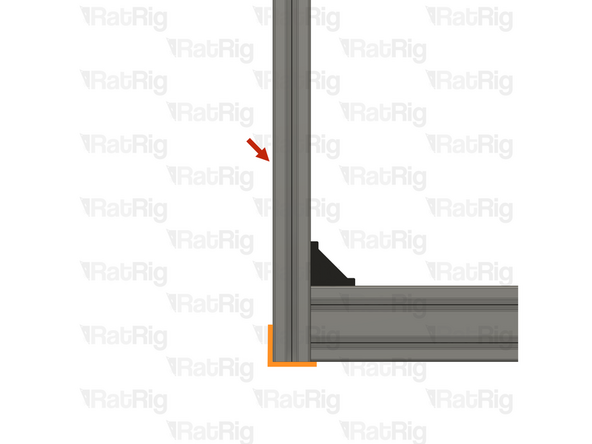
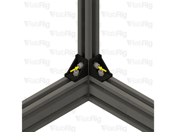
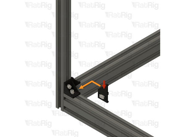
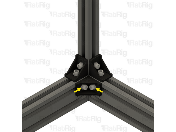
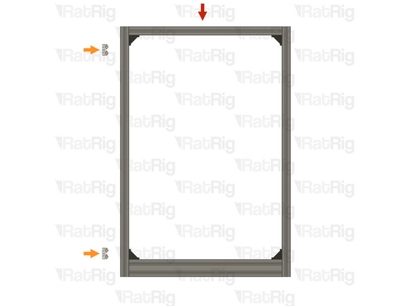
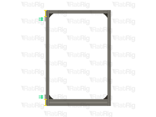
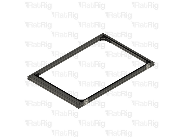
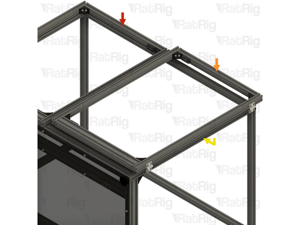
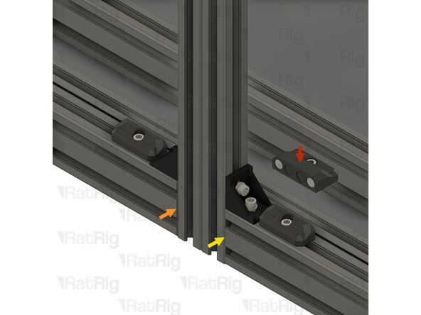
1x 1102mm 3030 extrusion
-
2x Inside hidden three way corner assemblies from Step 5
-
Tighten the M6x8 set screws to secure the corners to the extrusion
-
Ensure the extrusion is flush and square with the both hidden three way corner assemblies before and after tightening the set screws
-
Be careful while tightening the set screws, extreme force may break the three way hidden corner
-
-
-
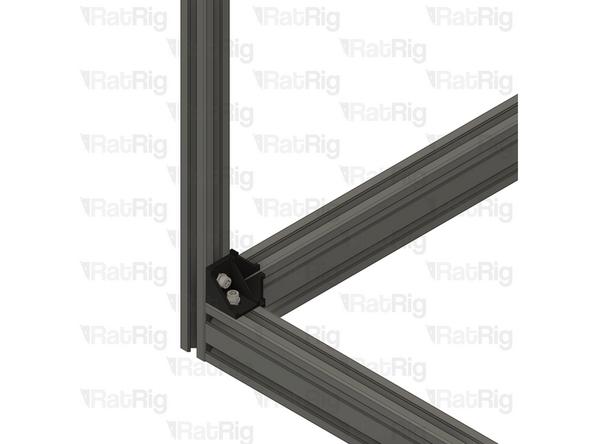
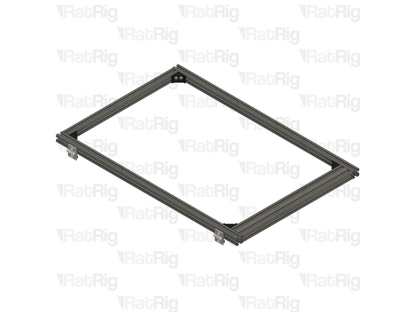
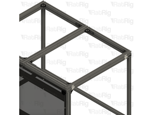
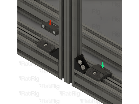
2x Assemblies from the previous step
-
2x 712mm 3030 extrusion
-
Assemble the enclosure top as shown, securing it together by tightening the M6x8 set screws
-
Ensure the extrusion is flush and square with the both hidden three way corner assemblies before and after tightening the set screws
-
Be careful while tightening the set screws, extreme force may break the three way hidden corner
-
-
-
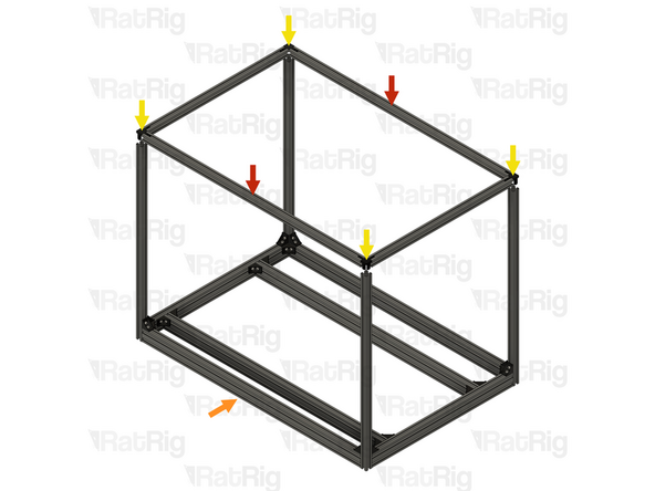
It is strongly recommended to have a second person assist with installing the upper frame, and also to manipulate the frame in the remaining steps. The enclosure weighs roughly 22KG without the panels installed
-
The enclosure is large and heavy and can cause injury if it were to fall
-
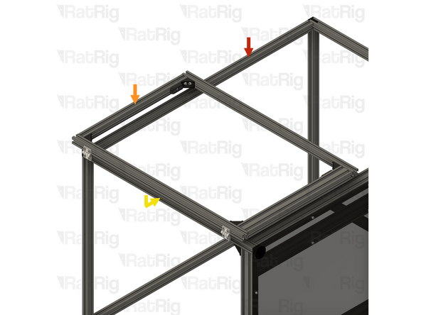
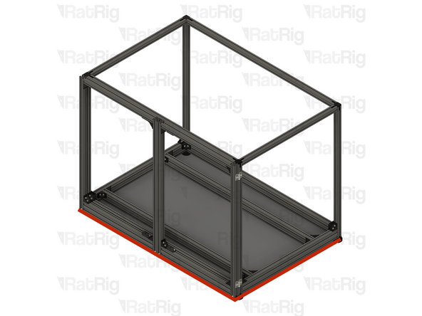
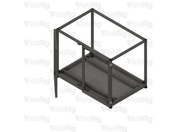
1x Enclosure top assembly from the previous step
-
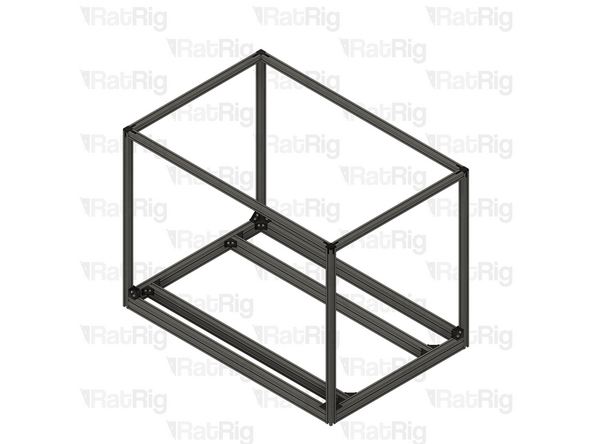
1x Enclosure assembly
-
Align the inside hidden three way corner assemblies with the upright 3030 extrusions
-
Once fully aligned and situated, tighten all M6x8 set screws to secure the enclosure frame together
-
Be careful while tightening the set screws, extreme force may break the three way hidden corner
-
-
-
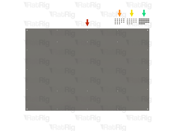
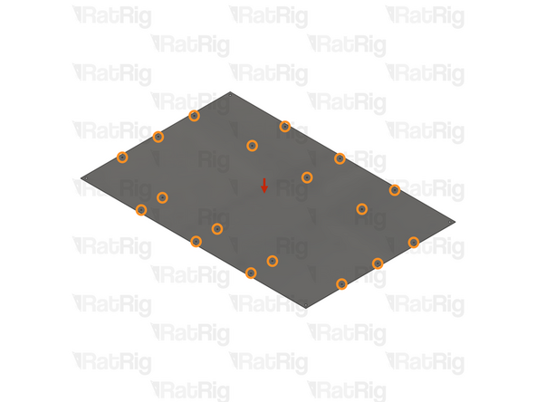
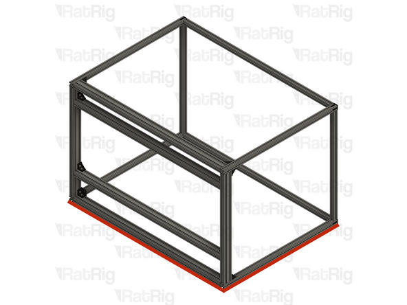
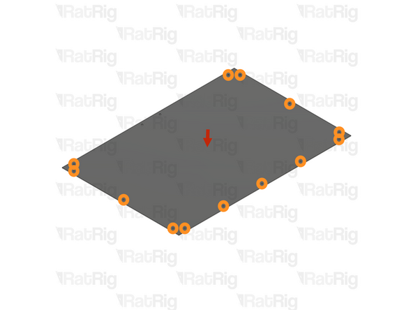
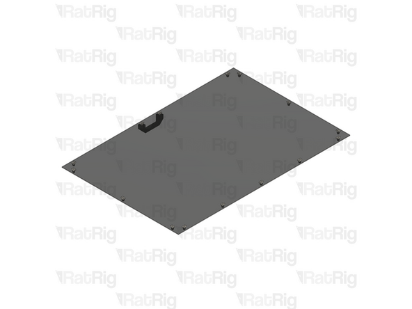
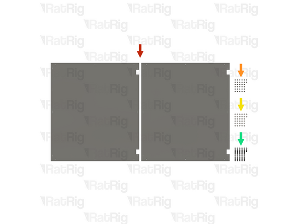
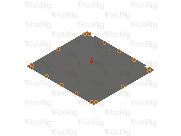
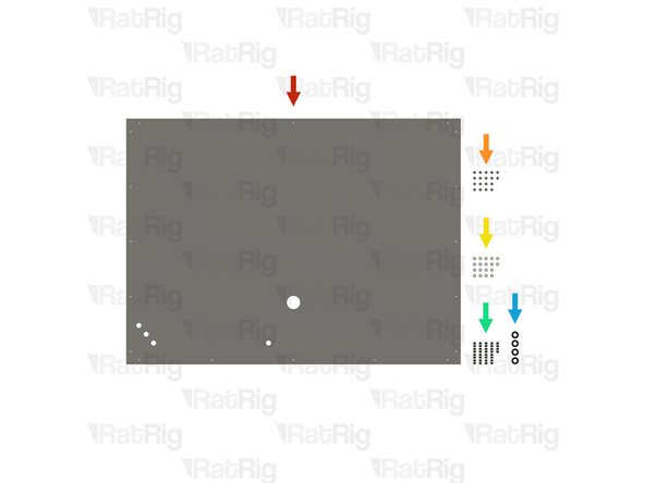
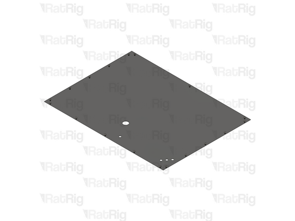
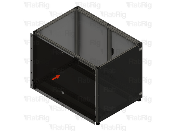
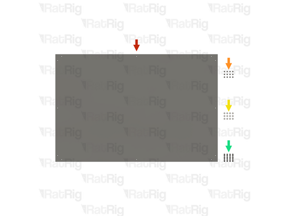
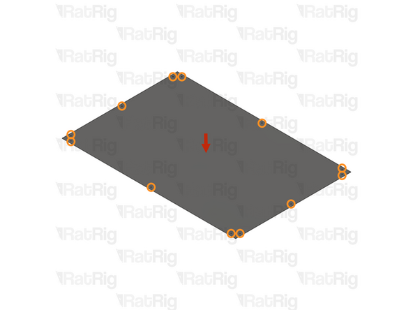
1x panel_enclosure_mill_base panel
-
18x M5x12 cap head screw
-
18x M5 washer
-
18x T-nut drop-in for 3030 - M5
-
-
-
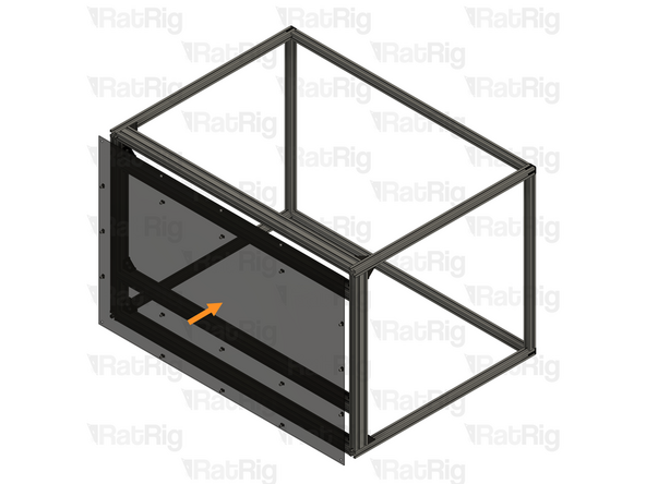
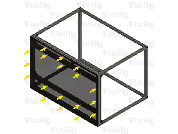
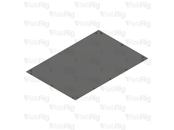
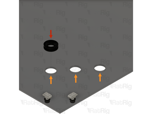
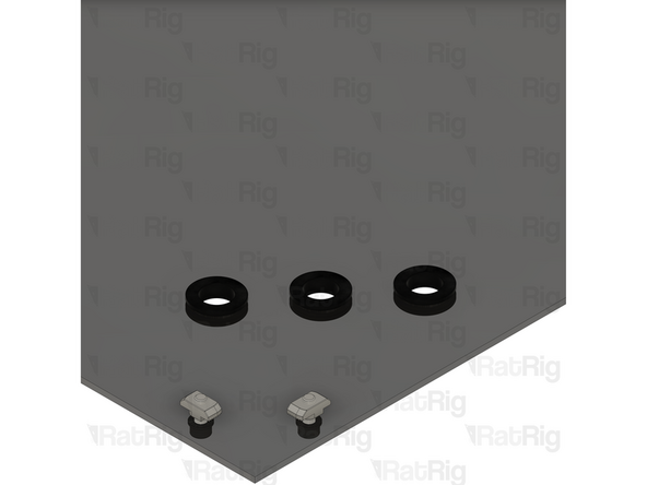
1x panel_enclosure_mill_base panel
-
For each of the 18x marked holes, install the mounting hardware as shown in Step 22
-
-
-
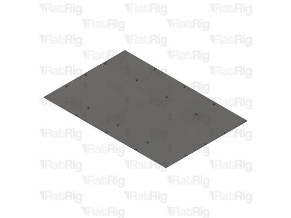
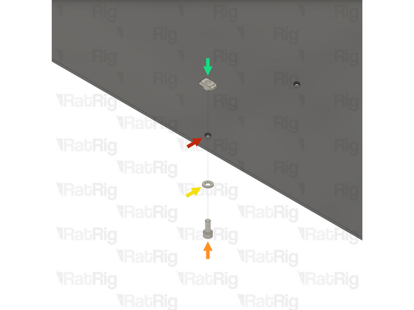
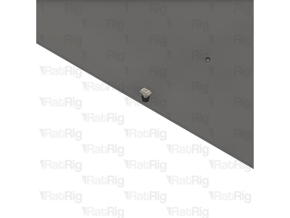
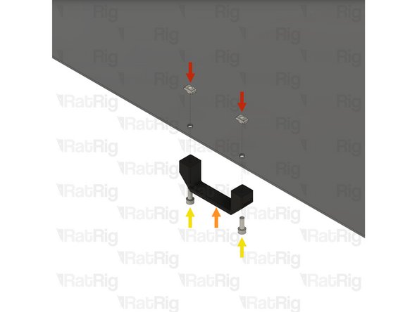
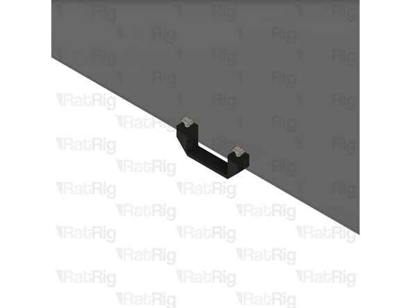
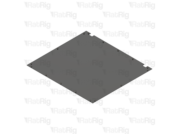
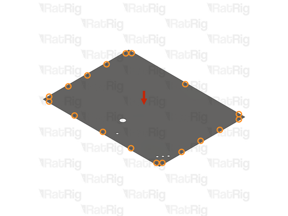
1x panel_enclosure_mill_base panel
-
1x M5x12 cap head screw
-
1x M5 washer
-
1x T-nut drop-in for 3030 - M5
-
Loosely thread the 3030 T-nuts onto the M5x12 screws. Do not tighten them at this point
-
-
-
It is strongly recommended to have a second person assist with manipulating the frame in this step
-
The enclosure is large and heavy and can cause injury if it were to fall
-
Rotate the enclosure frame assembly so that it lays on its back as shown
-
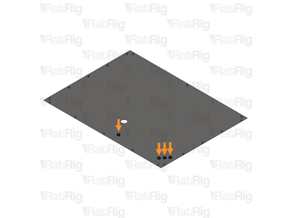
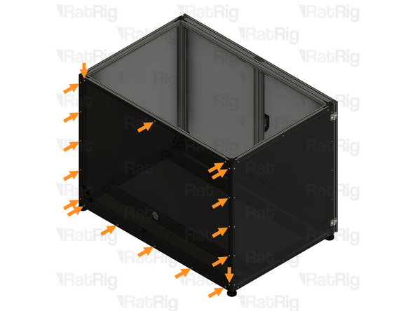
1x Base panel assembly from the previous step
-
Align the panel assembly to the frame as shown
-
Secure the panel in place by fastening the eighteen M5x12 screws
-
-
-
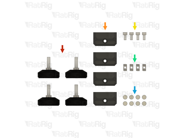
4x Leveling feet for 3030 - M8x30mm (Non-slip)
-
4x cnc_enclosure_magnet_frame_3030 printed part
-
4x M6x12 cap head screw
-
4x T-nut drop-in for 3030 - M6
-
8x Magnet - Neodymium disc - 10x4mm
-
-
-
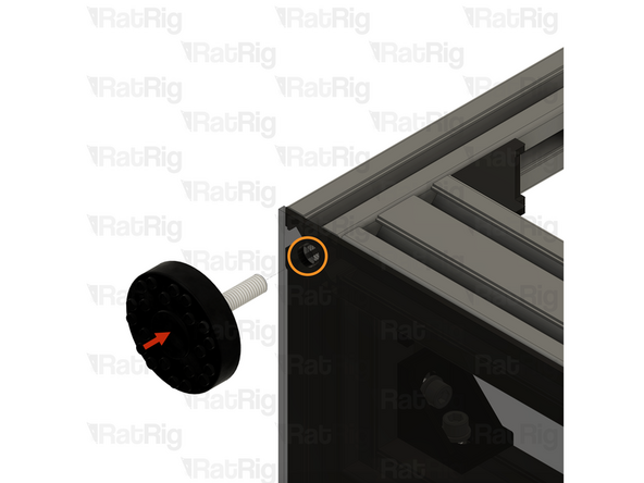
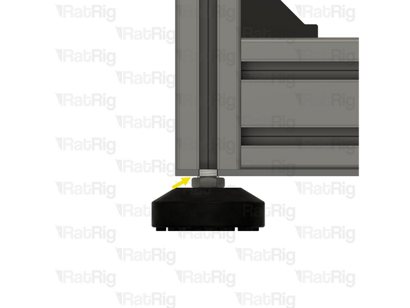
1x Leveling feet for 3030 - M8x30mm (Non-slip)
-
Install the foot by screwing the threaded section in to the tapped extrusion through the base panel as shown
-
Tighten the foot until the hex section nearly touches the panel
-
-
-
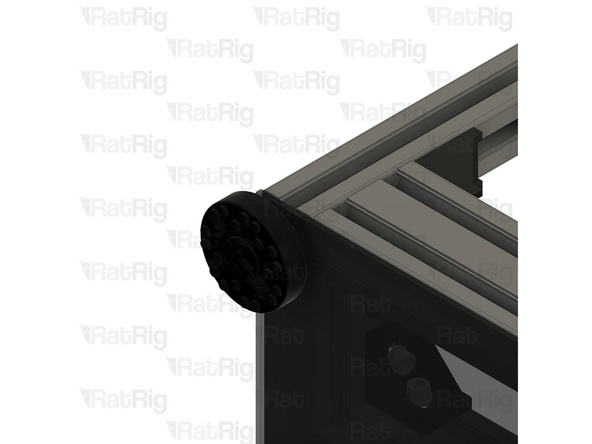
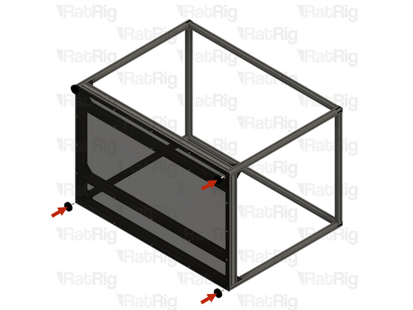
3x Leveling feet for 3030 - M8x30mm (Non-slip)
-
Install the remaining three feet into the frame assembly as shown
-
-
-
1x cnc_enclosure_magnet_frame_3030 printed part
-
2x Magnet - Neodymium disc - 10x4mm
-
Tip: Use a drop of super glue to prevent the magnets from coming loose over time
-
1x M6x12 cap head screw
-
1x T-nut drop-in for 3030 - M6
-
Loosely thread the 3030 T-nut onto the M6x12 screw. Do not tighten it at this point
-
-
-
4x 856mm 3030 extrusion
-
2x 521mm 3060 extrusion
-
2x 521mm 3030 extrusion
-
8x 3030 cast 90 degree corner assembly
-
-
-
1x 521mm 3060 extrusion
-
2x 3030 cast 90 degree corner assemblies
-
Install one corner assembly onto each end of the 521mm 3060 extrusions as shown. Tighten the M6x12 screw to secure them
-
Ensure the corner assemblies are flush and square with the ends of the extrusions after tightening the screws
-
Set these assemblies aside until Step 31
-
-
-
1x 521mm 3030 extrusion
-
2x 3030 cast 90 degree corner assemblies
-
Install one corner assembly onto each end of the 521mm 3030 extrusions as shown. Tighten the M6x12 screw to secure them
-
Ensure the corner assemblies are flush and square with the ends of the extrusions after tightening the screws
-
-
-
4x Hinge - metallic anodized for 3030
-
16x M6x14 countersink screw
-
20x T-nut drop-in for 3030 - M6
-
4x M6x12 cap head screw
-
8x Magnet - Neodymium disc - 10x4mm
-
4x V-Core 4 frame magnet holder - nylon
-
5.5M x Foam strip - 1x8mm - adhesive
-
-
-
-
1x V-Core 4 frame magnet holder - nylon
-
2x Magnet - Neodymium disc - 10x4mm
-
It is important to make sure the polarity of the magnets are correct. Use the assemblies from Step 27 to make sure the magnets do not repel each other
-
Tip: Use a drop of super glue to prevent the magnets from coming loose over time
-
1x M6x12 cap head screw
-
1x T-nut drop-in for 3030 - M6
-
Loosely thread the 3030 T-nut onto the M6x12 screw. Do not tighten it at this point
-
-
-
-
-
2x Door magnetic latch assembly from Step 34
-
Position the magnetic latch assemblies onto the upper and lower extrusions as shown. They should touch the 3030 cast 90 degree corners
-
Tighten the M6x12 marked screws to secure the magnetic latches to the door
-
Take care not to over-tighten the M6x12 screws as you can damage the nylon part
-
Set this assembly aside until Step 40
-
-
-
-
2x Door magnetic latch assembly from Step 34
-
Position the magnetic latch assemblies onto the upper and lower extrusions as shown. They should touch the 3030 cast 90 degree corners
-
Tighten the M6x12 marked screws to secure the magnetic latches to the door
-
Take care not to over-tighten the M6x12 screws as you can damage the nylon part
-
Set this assembly aside until Step 41
-
-
-
The 5.5 metres of foam strip needs to be cut into the following lengths:
-
4x 540mm lengths
-
2x 765mm lengths
-
The foam strip can easily be cut with regular scissors
-
Do not remove the backing from the foam strip lengths yet
-
-
-
1x Left door assembly from Step 36
-
Orient the door assembly as shown. The foam strip must be installed on the inside of the door
-
1x 765mm length of foam strip
-
2x 540mm length of foam strip
-
The foam strip has a protective backing which covers the adhesive. Peel the backing off each strip and apply them to the door assembly as shown
-
-
-
1x Right door assembly from Step 38
-
Orient the door assembly as shown. The foam strip must be installed on the inside of the door
-
1x 765mm length of foam strip
-
2x 540mm length of foam strip
-
The foam strip has a protective backing which covers the adhesive. Peel the backing off each strip and apply them to the door assembly as shown
-
-
-
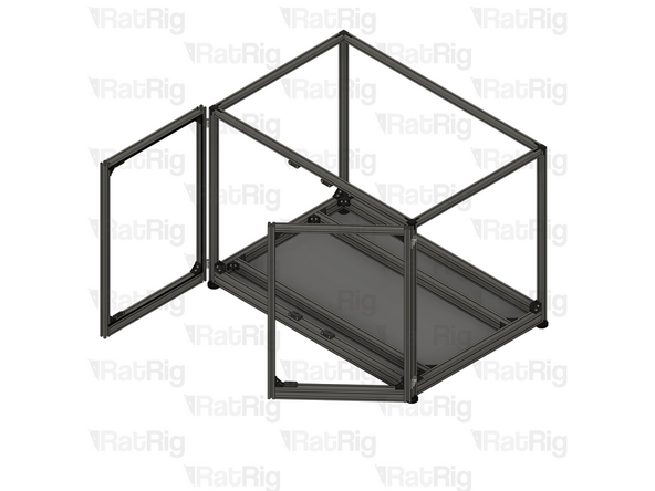
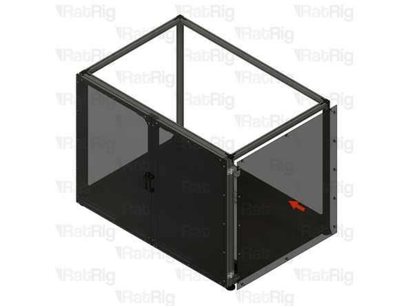
1x Enclosure assembly from Step 26
-
1x Left door assembly from Step 40
-
Place the left door assembly onto the enclosure as shown
-
Align the door assembly as shown, making sure the top of the door is level with the top of the enclosure
-
Tighten the four marked M6x14 countersink screws to fix the door assembly to the enclosure
-
-
-
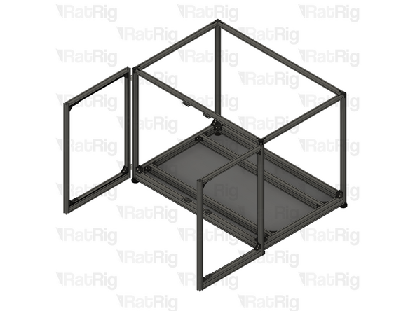
1x Enclosure assembly
-
1x Right door assembly from Step 42
-
Place the right door assembly onto the enclosure as shown
-
Align the door assembly as shown, making sure the top of the door is level with the top of the enclosure
-
Tighten the four marked M6x14 countersink screws to fix the door assembly to the enclosure
-
-
-
It is strongly recommended to have a second person assist with manipulating the frame in this step
-
The enclosure is large and heavy and can cause injury if it were to fall
-
Be careful as the doors can swing freely at this stage
-
Rotate the enclosure frame assembly so that it stands on its feet as shown
-
-
-
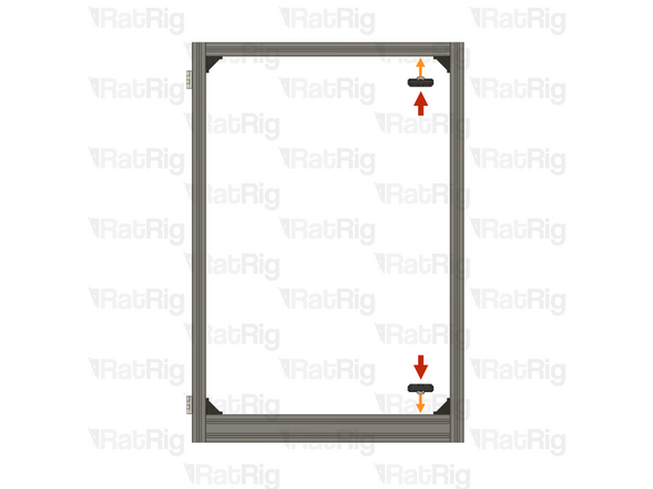
2x Frame magnetic latch assemblies from Step 27
-
Left door
-
Right door
-
Position the magnetic latch assemblies onto the enclosure assembly as shown, the magnets should help align them
-
Tighten the M6x12 marked screws to secure the magnetic latches to the enclosure
-
-
-
2x Frame magnetic latch assemblies from Step 27
-
Left door
-
Right door
-
Position the magnetic latch assemblies onto the enclosure assembly as shown, the magnets should help align them
-
Tighten the M6x12 marked screws to secure the magnetic latches to the enclosure
-
-
-
Test that both doors open and close without binding, and that the magnetic latches hold the doors closed
-
If the doors bind, make minor adjustments to the hinge positions until the doors move smoothly
-
If the magnetic latches do not hold the doors closed, adjust the position of the magnetic latches and check no magnets are repelling
-
-
-
2x panel_enclosure_mill_door panel
-
26x M5x12 cap head screw
-
26x M5 washer
-
26x T-nut drop-in for 3030 - M5
-
4x M6x16 cap head screw
-
4x T-nut drop-in for 3030 - M6
-
2x V-slot door handle
-
-
-
1x panel_enclosure_mill_door panel
-
For each of the 13x marked holes, install the mounting hardware as shown in Step 22
-
Loosely thread the 3030 T-nuts onto the M5x12 screws. Do not tighten them at this point
-
The door panels are identical for left and right, assemble both the same
-
-
-
2x T-nut drop-in for 3030 - M6
-
1x V-slot door handle
-
2x M6x16 cap head screw
-
Loosely thread the 3030 T-nuts onto the M6x16 screws. Do not tighten them at this point
-
The door panels are identical for left and right, assemble both the same
-
-
-
2x Door panel assembly from the previous step
-
Align the panel assembly to the door as shown
-
Secure the panel in place by fastening the thirteen M5x12 screws
-
Tighten the two M6x16 screws in the handle
-
-
-
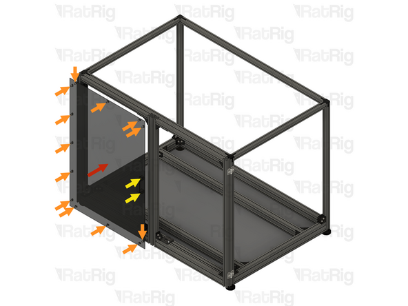
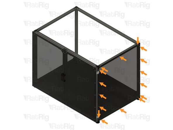
2x panel_enclosure_mill_side panel
-
32x M5x12 cap head screw
-
32x M5 washer
-
32x T-nut drop-in for 3030 - M5
-
-
-
1x panel_enclosure_mill_side panel
-
For each of the sixteen marked holes, install the mounting hardware as shown in Step 22
-
Loosely thread the 3030 T-nuts onto the M5x12 screws. Do not tighten them at this point
-
The side panels are identical for left and right, assemble both the same
-
-
-
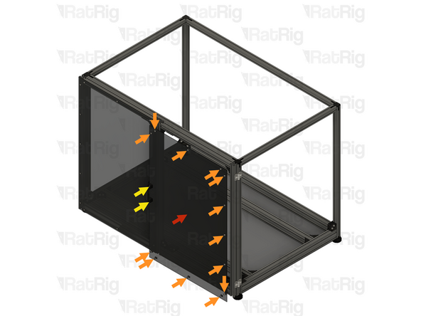
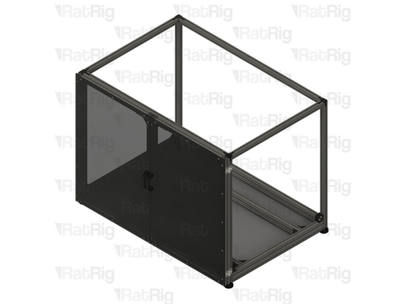
2x Side panel assembly from the previous step
-
Align the panel assembly to the enclosure as shown
-
Secure the panel in place by fastening the sixteen M5x12 screws
-
Repeat for the second side panel assembly
-
-
-
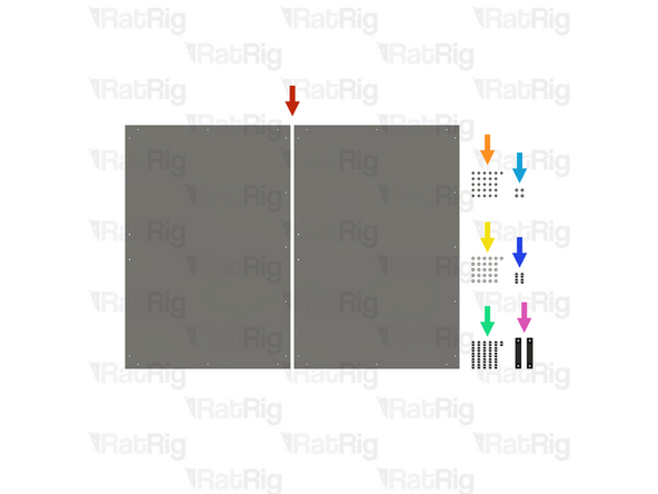
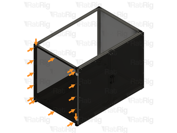
1x panel_enclosure_mill_back panel
-
18x M5x12 cap head screw
-
18x M5 washer
-
18x T-nut drop-in for 3030 - M5
-
4x Grommet - 18x14x7mm
-
-
-
1x panel_enclosure_mill_back panel
-
For each of the eighteen marked holes, install the mounting hardware as shown in Step 22
-
Loosely thread the 3030 T-nuts onto the M5x12 screws. Do not tighten them at this point
-
-
-
4x Grommet - 18x14x7mm
-
Install a grommet into each of the four marked holes
-
-
-
1x Back panel assembly from the previous step
-
Align the panel assembly to the enclosure as shown
-
Secure the panel in place by fastening the eighteen M5x12 screws
-
-
-
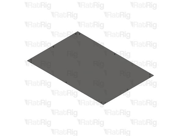
1x panel_enclosure_mill_lid panel
-
12x M5x12 cap head screw
-
12x M5 washer
-
12x T-nut drop-in for 3030 - M5
-
-
-
1x panel_enclosure_mill_lid panel
-
For each of the twelve marked holes, install the mounting hardware as shown in Step 22
-
Loosely thread the 3030 T-nuts onto the M5x12 screws. Do not tighten them at this point
-
-
-
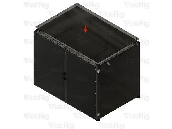
1x Lid panel assembly from the previous step
-
Align the panel assembly to the enclosure as shown
-
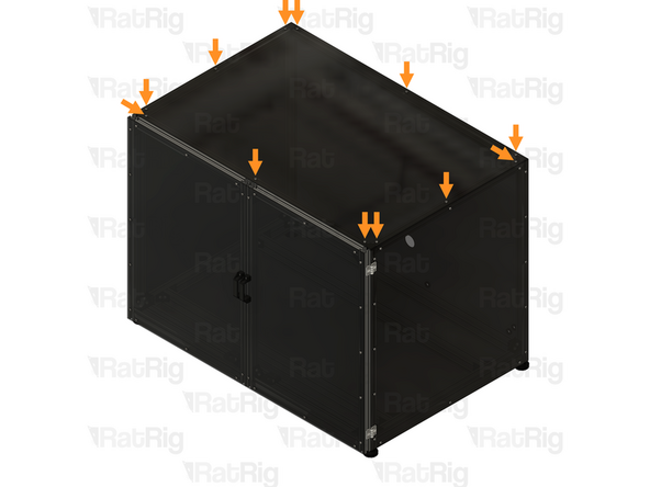
Secure the panel in place by fastening the twelve M5x12 screws
-
-
-
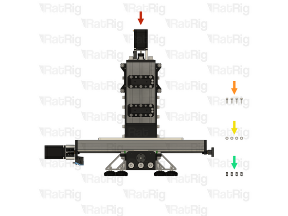
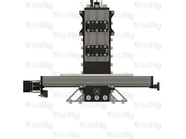
1x Rat Rig Mill assembly
-
4x M6x16 cap head screw
-
4x M6 washer
-
4x T-nut drop-in for 3030 - M6
-
-
-
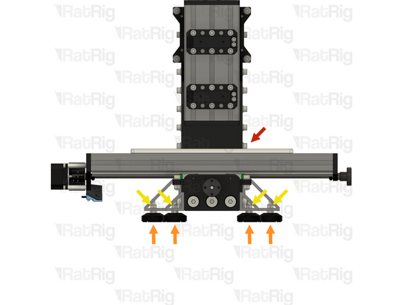
1x Rat Rig Mill assembly
-
4x Leveling feet for 3030 - M8x30mm (Non-slip)
-
4x M6 hex locking nut
-
Unscrew and remove all four levelling feet, and their locking hex nuts, from the Mill assembly
-
Store the feet and locking hex nuts so they can be used in the future if needed
-
-
-
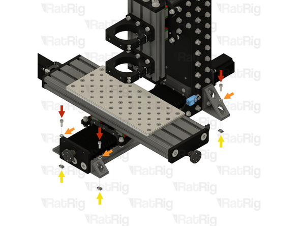
4x M6x16 cap head screw
-
4x M6 washer
-
4x T-nut drop-in for 3030 - M6
-
Loosely thread the 3030 T-nuts onto the M6x16 screws. Do not tighten them at this point
-
-
-
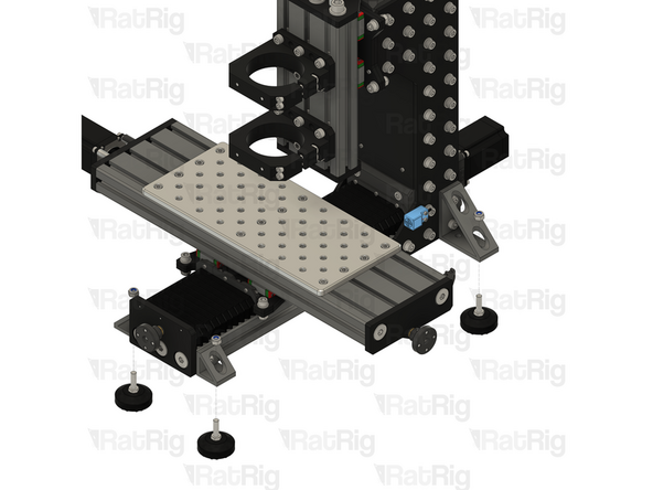
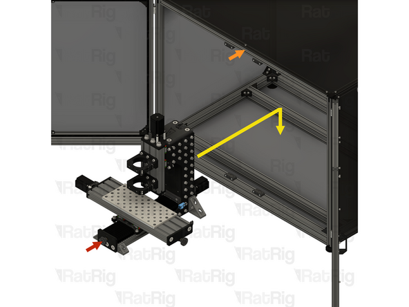
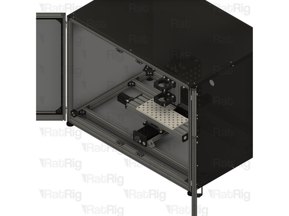
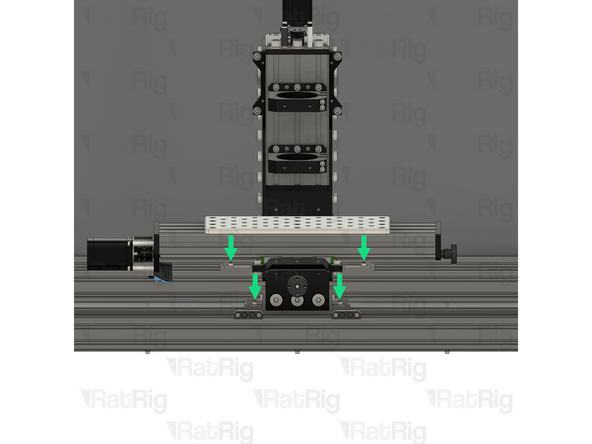
1x Rat Rig Mill assembly
-
1x Enclosure Assembly
-
Carefully lift the Mill into the enclosure. Align the brackets with the horizontal 3060 extrusions making sure the T-nuts drop into the extrusion slot
-
4x M6x16 cap head screw
-
Fully tighten the M6x16 screws to secure the Rat Rig Mill to the enclosure
-